Project 12: POSIX Shared Memory Ring Buffer
Create a POSIX shared-memory ring buffer for streaming data.
Quick Reference
| Attribute | Value |
|---|---|
| Difficulty | Level 4 (Expert) |
| Time Estimate | 2 Weeks |
| Main Programming Language | C (Alternatives: Rust) |
| Alternative Programming Languages | Rust |
| Coolness Level | Level 4 (Hardcore Tech Flex) |
| Business Potential | Level 4 (Open Core Infrastructure) |
| Prerequisites | C programming, basic IPC familiarity, Linux tools (strace/ipcs) |
| Key Topics | shared memory, ring buffer, semaphores |
1. Learning Objectives
By completing this project, you will:
- Build a working IPC-based system aligned with Stevens Vol. 2 concepts.
- Implement robust lifecycle management for IPC objects.
- Handle errors and edge cases deterministically.
- Document and justify design trade-offs.
- Benchmark or validate correctness under load.
2. All Theory Needed (Per-Concept Breakdown)
Shared Memory and Ring Buffers
Fundamentals
Shared memory is the fastest IPC mechanism because it avoids kernel copies. Multiple processes map the same physical pages into their address spaces, allowing them to read and write data directly. However, shared memory provides no synchronization; you must use mutexes, semaphores, or lock-free protocols to coordinate access.
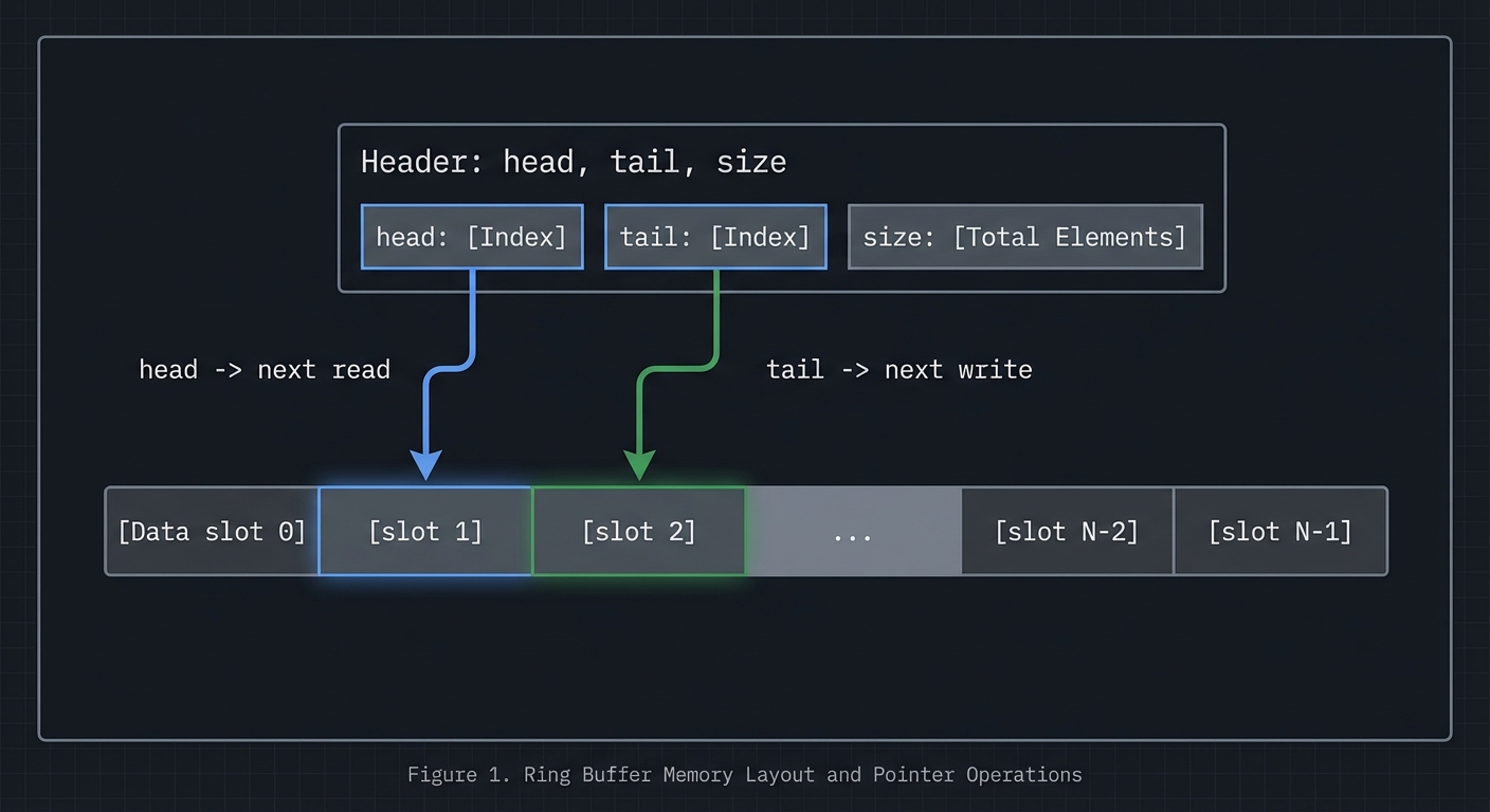
A ring buffer is a circular queue implemented in shared memory. It uses head and tail indices to track where data is written and read. This data structure is ideal for streaming data between processes because it provides constant-time operations and good cache locality.
Deep Dive into the Concept
In POSIX shared memory, you create a named object with shm_open, size it with ftruncate, and map it with mmap. System V shared memory uses shmget and shmat. Both approaches yield a pointer you can use like normal memory. The challenge is establishing a shared layout: both processes must agree on the structure of the shared memory region, including alignment and padding. A typical layout includes a header with metadata (size, head, tail, flags) followed by the data region.
Ring buffers require careful handling of wrap-around and full/empty detection. The simplest approach uses a count field protected by a mutex. More advanced approaches use head and tail indices with one slot left empty to distinguish full from empty. In shared memory across processes, you must also consider cache coherence and false sharing: if head and tail are updated by different processes, place them on separate cache lines to avoid contention.
Synchronization strategies vary. For single-producer/single-consumer, you can use semaphores or lock-free atomic indices. For multi-producer/multi-consumer, you typically need a mutex or more complex lock-free design. The design you choose affects latency, throughput, and complexity. This project will have you implement a correct, well-documented choice rather than chasing micro-optimizations.
How this fits on projects
Shared memory is the core of the ring buffer and image processor projects, and it is used as a local cache in the distributed KV store.
Definitions & key terms
- Shared memory -> Pages mapped into multiple processes.
- Ring buffer -> Circular queue with head/tail indices.
- False sharing -> Performance penalty from shared cache lines.
Mental model diagram (ASCII)
[Header: head, tail, size]
[Data slot 0][slot 1][slot 2]...[slot N-1]
head -> next read, tail -> next write
How it works (step-by-step, with invariants and failure modes)
- Create shared memory and map into processes.
- Initialize header fields and buffer.
- Producer writes at tail and advances index.
- Consumer reads at head and advances index.
- Synchronize to avoid reading empty or writing full.
Failure modes: inconsistent indices, missing synchronization, cache contention.
Minimal concrete example
struct shm_ring { size_t head, tail, cap; char data[CAP]; };
// producer writes data[tail % cap] then tail++
**Common misconceptions**

- "Shared memory is safe by default." -> It provides no synchronization.
- "Ring buffers are trivial." -> Full/empty detection is subtle.
- "More locking is always safer." -> It can kill performance and cause deadlocks.

**Check-your-understanding questions**

1. Why do you need synchronization with shared memory?
2. How can you distinguish full vs empty in a ring buffer?
3. What is false sharing and how do you avoid it?

**Check-your-understanding answers**

1. Multiple processes can write concurrently, causing races.
2. Reserve one slot or track count explicitly.
3. Place frequently updated fields on separate cache lines.

**Real-world applications**

- High-throughput logging pipelines.
- In-memory caches and queues.

**Where you’ll apply it**

- In this project: §3.2 Functional Requirements, §4.4 Data Structures.
- Also used in: [P13-sysv-shm-images.md](P13-sysv-shm-images.md), [P18-rpc-kvstore.md](P18-rpc-kvstore.md).

**References**

- Stevens, "UNP Vol 2" Ch. 12-13.
- `man 2 shm_open`, `man 2 shmget`, `man 2 mmap`.

**Key insights**

- Shared memory is fast because it removes copies, but it moves correctness into your hands.

**Summary**

Shared memory and ring buffers enable high throughput IPC, provided you design synchronization and layout carefully.

**Homework/Exercises to practice the concept**

1. Implement a ring buffer with a mutex and cond vars.
2. Add padding to reduce false sharing and measure throughput.
3. Test full/empty conditions under load.

**Solutions to the homework/exercises**

1. Use a shared header with head/tail/count and pthread mutex in shared memory.
2. Align head and tail on separate cache lines.
3. Run with a producer and consumer loop; assert invariants.


---

## 3. Project Specification

### 3.1 What You Will Build

Create a POSIX shared-memory ring buffer for streaming data.

### 3.2 Functional Requirements

1. **Requirement 1**: POSIX shm_open + mmap
2. **Requirement 2**: Producer/consumer with synchronization
3. **Requirement 3**: Handle full/empty states

### 3.3 Non-Functional Requirements

- **Performance**: Must handle at least 10,000 messages/operations without failure.
- **Reliability**: IPC objects are cleaned up on shutdown or crash detection.
- **Usability**: CLI output is readable with clear error codes.

### 3.4 Example Usage / Output

```text
./shm_producer --size 4096 &
./shm_consumer --size 4096
### 3.5 Data Formats / Schemas / Protocols

Header: {cap, head, tail}; data region is byte array.

### 3.6 Edge Cases

- Buffer full
- Reader slower than writer
- Stale shm on restart

### 3.7 Real World Outcome

You will have a working IPC subsystem that can be run, traced, and tested in a reproducible way.

#### 3.7.1 How to Run (Copy/Paste)

```bash
make
./run_demo.sh
#### 3.7.2 Golden Path Demo (Deterministic)

```bash
./run_demo.sh --mode=golden
Expected output includes deterministic counts and a final success line:

```text
OK: golden scenario completed
#### 3.7.3 Failure Demo (Deterministic)

```bash
./run_demo.sh --mode=failure
Expected output:

```text
ERROR: invalid input or unavailable IPC resource
exit=2
---
## 4. Solution Architecture
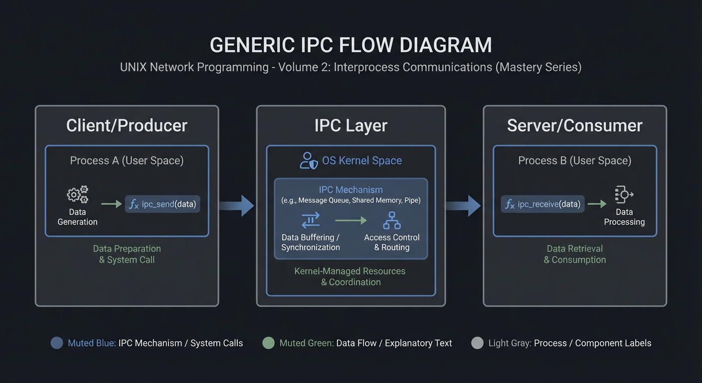
### 4.1 High-Level Design
Client/Producer -> IPC Layer -> Server/Consumer
4.2 Key Components
| Component | Responsibility | Key Decisions |
|---|---|---|
| IPC Setup | Create/open IPC objects | POSIX vs System V choices |
| Worker Loop | Send/receive messages | Blocking vs non-blocking |
| Cleanup | Unlink/remove IPC objects | Crash safety |
4.3 Data Structures (No Full Code)
struct message {
  int id;
  int len;
  char payload[256];
};
### 4.4 Algorithm Overview

**Key Algorithm: IPC Request/Response**
1. Initialize IPC resources.
2. Client sends request.
3. Server processes and responds.
4. Cleanup on exit.

**Complexity Analysis:**
- Time: O(n) in number of messages.
- Space: O(1) per message plus IPC buffer.

---

## 5. Implementation Guide

### 5.1 Development Environment Setup

```bash
sudo apt-get install build-essential
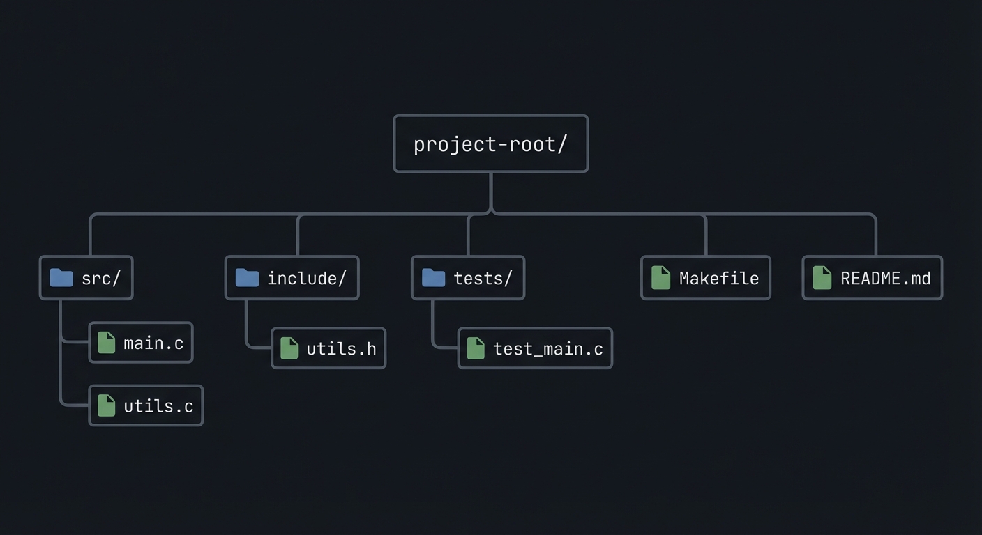
### 5.2 Project Structure
project-root/
├── src/
├── include/
├── tests/
├── Makefile
└── README.md
5.3 The Core Question You’re Answering
“How do you move data at memory speed across processes safely?”
5.4 Concepts You Must Understand First
- IPC object lifecycle (create/open/unlink)
- Blocking vs non-blocking operations
- Error handling with errno
5.5 Questions to Guide Your Design
- What invariants guarantee correctness in this IPC flow?
- How will you prevent resource leaks across crashes?
- How will you make the system observable for debugging?
5.6 Thinking Exercise
Before coding, sketch the IPC lifecycle and identify where deadlock could occur.
5.7 The Interview Questions They’ll Ask
- Why choose this IPC mechanism over alternatives?
- What are the lifecycle pitfalls?
- How do you test IPC code reliably?
5.8 Hints in Layers
Hint 1: Start with a single producer and consumer.
Hint 2: Add logging around every IPC call.
Hint 3: Use strace or ipcs to verify resources.
5.9 Books That Will Help
| Topic | Book | Chapter |
|---|---|---|
| IPC fundamentals | Stevens, UNP Vol 2 | Relevant chapters |
| System calls | APUE | Ch. 15 |
5.10 Implementation Phases
Phase 1: Foundation (2-4 hours)
Goals:
- Create IPC objects.
- Implement a minimal send/receive loop.
Tasks:
- Initialize IPC resources.
- Implement basic client and server.
Checkpoint: Single request/response works.
Phase 2: Core Functionality (4-8 hours)
Goals:
- Add error handling and cleanup.
- Support multiple clients or concurrent operations.
Tasks:
- Add structured message format.
- Implement cleanup on shutdown.
Checkpoint: System runs under load without leaks.
Phase 3: Polish & Edge Cases (2-4 hours)
Goals:
- Add deterministic tests.
- Document behaviors.
Tasks:
- Add golden and failure scenarios.
- Document limitations.
Checkpoint: Tests pass, behavior documented.
5.11 Key Implementation Decisions
| Decision | Options | Recommendation | Rationale |
|---|---|---|---|
| Blocking mode | blocking vs non-blocking | blocking | Simpler for first version |
| Cleanup | manual vs automated | explicit cleanup | Avoid stale IPC objects |
6. Testing Strategy
6.1 Test Categories
| Category | Purpose | Examples |
|---|---|---|
| Unit Tests | Validate helpers | message encode/decode |
| Integration Tests | IPC flow | client-server round trip |
| Edge Case Tests | Failure modes | missing queue, full buffer |
6.2 Critical Test Cases
- Single client request/response works.
- Multiple requests do not corrupt state.
- Failure case returns exit code 2.
6.3 Test Data
Input: “hello” Expected: “hello”
7. Common Pitfalls & Debugging
7.1 Frequent Mistakes
| Pitfall | Symptom | Solution |
|---|---|---|
| Not cleaning IPC objects | Next run fails | Add cleanup on exit |
| Blocking forever | Program hangs | Add timeouts or non-blocking mode |
| Incorrect message framing | Corrupted data | Add length prefix and validate |
7.2 Debugging Strategies
- Use
strace -fto see IPC syscalls. - Use
ipcsor/dev/mqueueto inspect objects.
7.3 Performance Traps
- Small queue sizes cause frequent blocking.
8. Extensions & Challenges
8.1 Beginner Extensions
- Add verbose logging.
- Add a CLI flag to toggle non-blocking mode.
8.2 Intermediate Extensions
- Add request timeouts.
- Add a metrics report.
8.3 Advanced Extensions
- Implement load testing with multiple clients.
- Add crash recovery logic.
9. Real-World Connections
9.1 Industry Applications
- IPC services in local daemons.
- Message-based coordination in legacy systems.
9.2 Related Open Source Projects
- nfs-utils - Uses RPC and IPC extensively.
- systemd - Uses multiple IPC mechanisms.
9.3 Interview Relevance
- Demonstrates system call knowledge and concurrency reasoning.
10. Resources
10.1 Essential Reading
- Stevens, “UNP Vol 2”.
- Kerrisk, “The Linux Programming Interface”.
10.2 Video Resources
- Unix IPC lectures from OS courses.
10.3 Tools & Documentation
man 7 ipc,man 2for each syscall.
10.4 Related Projects in This Series
11. Self-Assessment Checklist
11.1 Understanding
- I can describe IPC object lifecycle.
- I can explain blocking vs non-blocking behavior.
- I can reason about failure modes.
11.2 Implementation
- All functional requirements are met.
- Tests pass.
- IPC objects are cleaned up.
11.3 Growth
- I can explain design trade-offs.
- I can explain this project in an interview.
12. Submission / Completion Criteria
Minimum Viable Completion:
- Basic IPC flow works with correct cleanup.
- Error handling returns deterministic exit codes.
Full Completion:
- Includes tests and deterministic demos.
- Documents trade-offs and limitations.
Excellence (Going Above & Beyond):
- Adds performance benchmarking and crash recovery.