Spatial Computing & XR Mastery - Real World Projects
Goal: To deeply understand how digital information is mapped, rendered, and interacted with in 3D physical space. You will move beyond being a “user” of engines like Unity/Unreal to understanding the fundamental mathematics of 3D projection, the physics of light, the computer vision behind SLAM (Simultaneous Localization and Mapping), and the human-centric design of spatial UI/UX. By the end, you’ll be able to build the core components of a spatial engine from scratch and understand the hardware-software bridge that enables Mixed Reality.
Why Spatial Computing Matters
For decades, we’ve interacted with computers through “rectangular windows”—2D screens that demand our full attention. Spatial computing breaks the frame. It merges the digital and physical, treating the entire world as a canvas. This isn’t just about gaming; it’s the next major computing paradigm, often called the “Spatial Era.”
Consider the stakes and the scale:
- The Shift: We are moving from “looking at” computers to “being inside” or “co-existing with” them. This requires a 10x improvement in latency, tracking precision, and display technology.
- The Hardware: Devices like the Apple Vision Pro and Meta Quest 3 are essentially high-performance Linux/Android computers with 10+ cameras and dedicated silicon for computer vision.
- Critical Applications: Beyond entertainment, XR is revolutionizing:
- Surgery: Surgeons use AR to see a patient’s internal anatomy (CT scans) overlaid directly on their body during procedures.
- Manufacturing: Technicians at Boeing use AR to see wiring diagrams overlaid on aircraft fuselages, reducing error rates by 90%.
- Telepresence: Spatial audio and 3D reconstruction make “calling” someone feel like they are sitting in the room with you.
- The Complexity: It is the ultimate multidisciplinary field: Linear Algebra + Optics + Computer Vision + Low-latency Systems + Psychology. Understanding the engine internals (why a 4x4 matrix is used for rotation) and the tracking logic (how a camera knows it moved 2cm left) is what separates a script-kiddie from an XR Engineer.
The Spatial Hierarchy: From Pixels to Presence
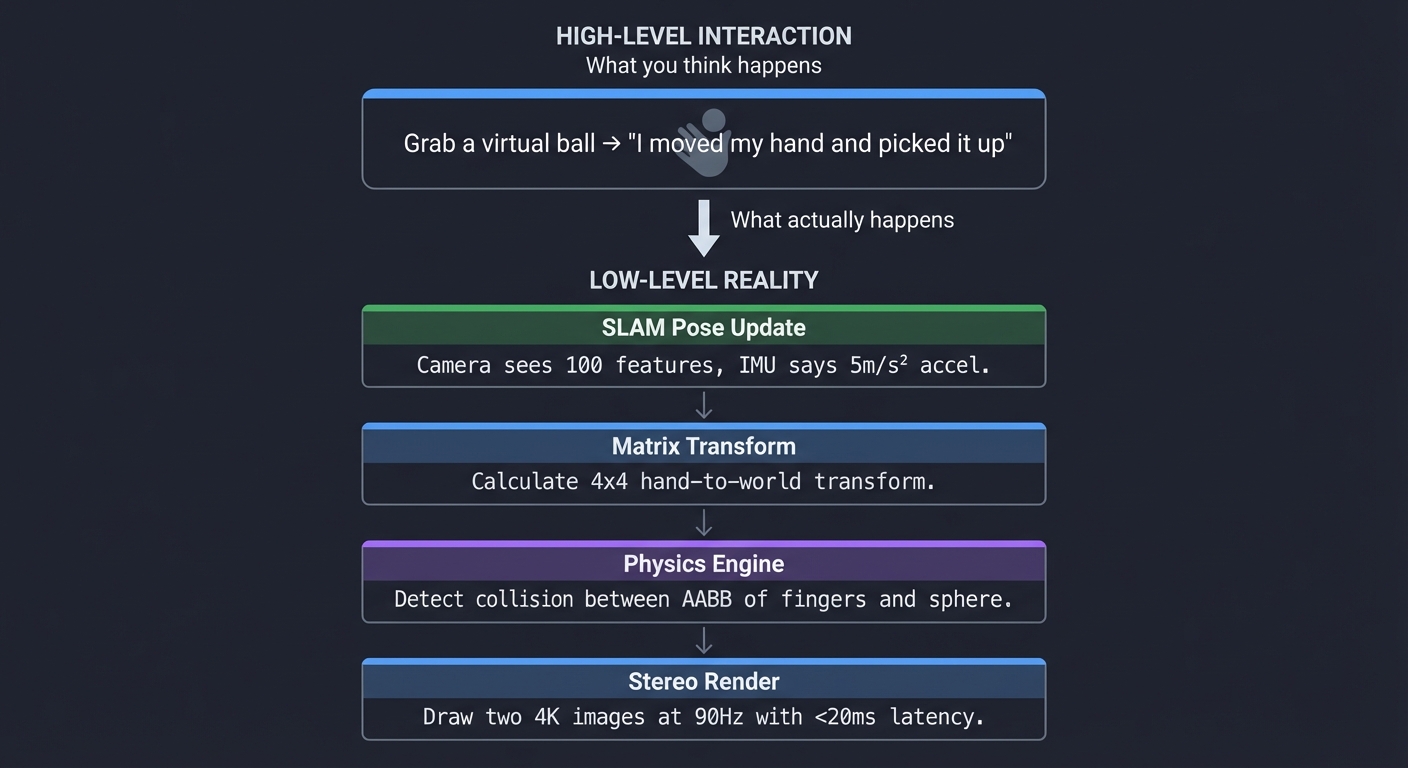
High-level interaction        What you think happens
        ↓
    Grab a virtual ball  →     "I moved my hand and picked it up"
        ↓
Low-level reality             What actually happens
        ↓
    SLAM Pose Update     →     Camera sees 100 features, IMU says 5m/s² accel.
    Matrix Transform     →     Calculate 4x4 hand-to-world transform.
    Physics Engine       →     Detect collision between AABB of fingers and sphere.
    Stereo Render        →     Draw two 4K images at 90Hz with <20ms latency.
Core Concept Analysis
1. The Rendering Pipeline & Transformations
At the heart of XR is the ability to place a 3D point $(x, y, z)$ on a 2D retina or screen. This involves a chain of matrix multiplications that transform coordinates from the “model” space to the “screen” space.
    Local Space (Model)
          |
    [Model Matrix] (Position/Rotation of Object)
          v
    World Space (The Room)
          |
    [View Matrix] (Position/Rotation of Your Head)
          v
    View Space (Camera's perspective)
          |
    [Projection Matrix] (FOV, Aspect Ratio, Near/Far clipping)
          v
    Clip Space (Normalized Device Coordinates)
          |
    [Viewport Transform] (Scaling to screen pixels)
          v
    Screen Space (Pixels)
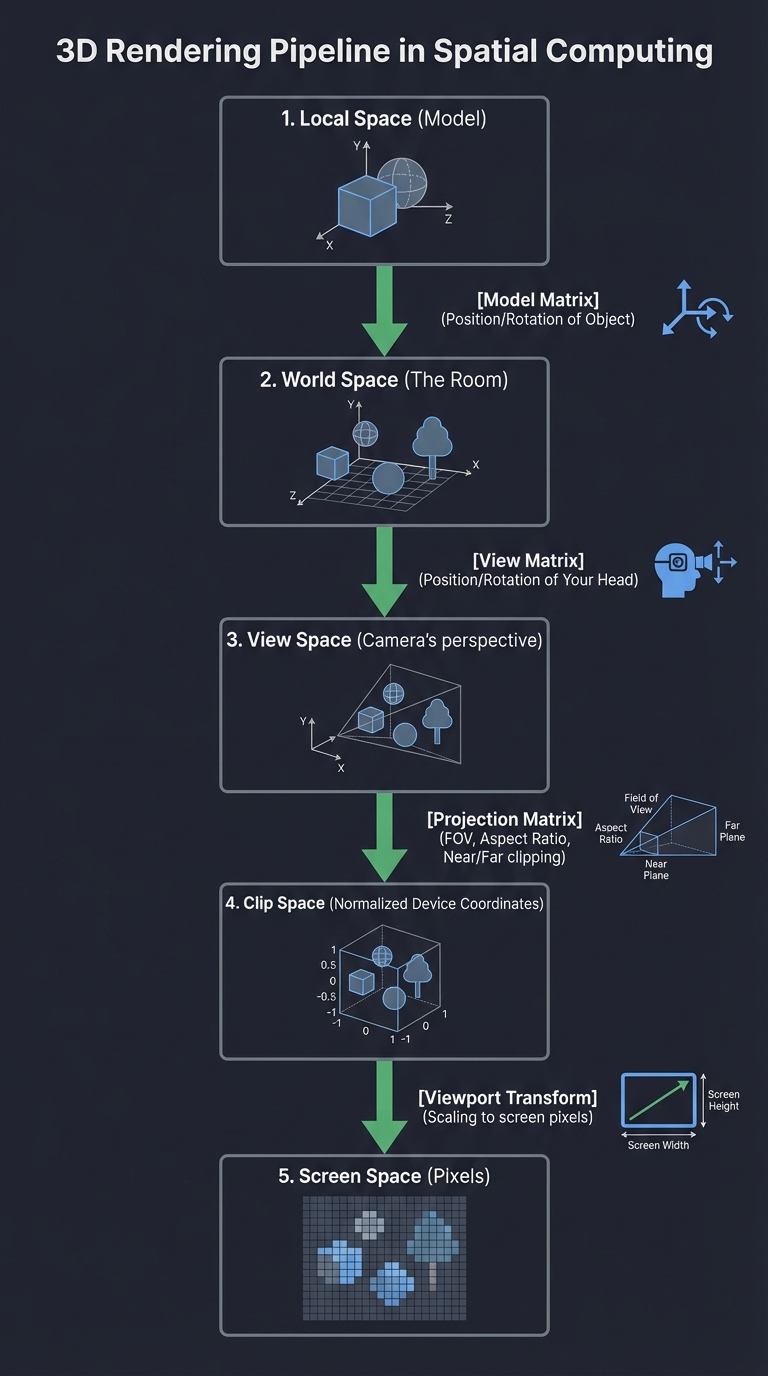
Key insight: Everything in spatial computing is relative. Your “head” is a moving coordinate system inside a “world” coordinate system. If you don’t update the View Matrix at 90Hz, the world “swims” or “lags,” causing nausea.
2. 6 Degrees of Freedom (6DoF)
To feel “present,” a device must track its position and orientation in space. Unlike 3DoF (which only tracks rotation like a 360 video), 6DoF allows you to walk through the virtual world.
          Y (Up/Down)
          ^
          |
          |   / Z (Forward/Back)
          |  /
          | /
          |/-----------> X (Left/Right)
         /|
        / |
       /  |

  1. Pitch (Rotation around X) - Looking Up/Down
  2. Yaw   (Rotation around Y) - Looking Left/Right
  3. Roll  (Rotation around Z) - Tilting Head
  4. X-Trans - Moving Left/Right
  5. Y-Trans - Moving Up/Down
  6. Z-Trans - Moving Forward/Back
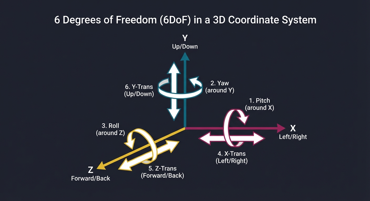
Key insight: Most mobile phones only have a 3DoF IMU (gyroscope/accelerometer). 6DoF requires “Computer Vision” (SLAM) to calculate the translation (X, Y, Z) by observing the environment.
3. SLAM: The Eyes of the System
Simultaneous Localization and Mapping is the “magic” that lets a headset know where it is without external sensors. It uses computer vision to find “anchor points” in the room, builds a map of those points, and tracks the camera relative to that map.
    [Camera Frame] ---> [Feature Detection] ---> [Feature Matching]
                               |
                               v                       v
    [Pose Update] <--- [Motion Estimation] <--- [Map Integration]
          |
          +--------------------------------------------+
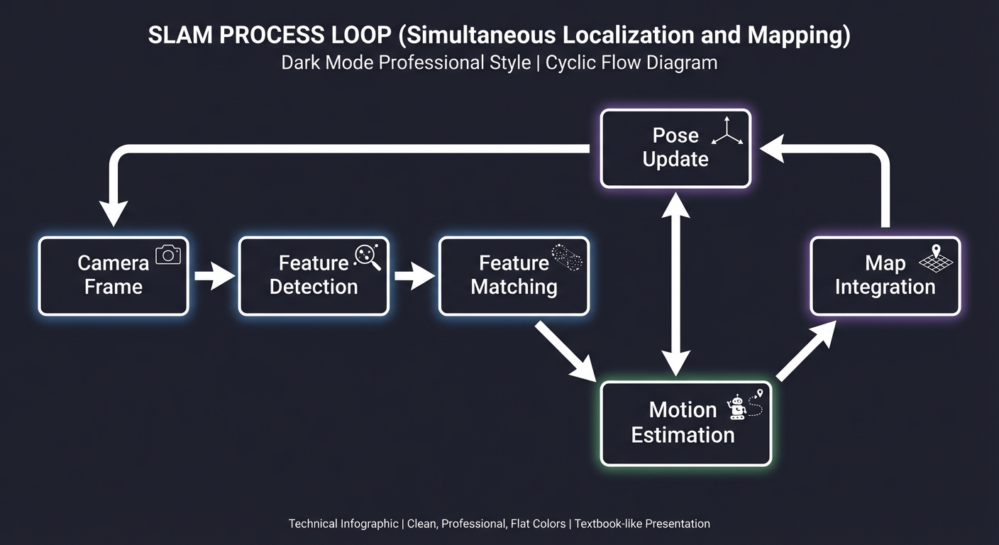
Key insight: SLAM is a loop. The more you move, the better the map becomes, but the more “drift” can accumulate. Understanding the “Loop Closure” problem is fundamental to stable XR.
4. Stereoscopic Rendering & Binocular Vision
To create depth, we render two images from slightly different perspectives, mimicking our eyes. The distance between them is the IPD (Interpupillary Distance).
      Left Eye             Right Eye
    [ Frustum L ]        [ Frustum R ]
         \                  /
          \   Target Obj   /
           \      X       /
            \            /
             \ IPD /2   /
              \---v---
                 Head
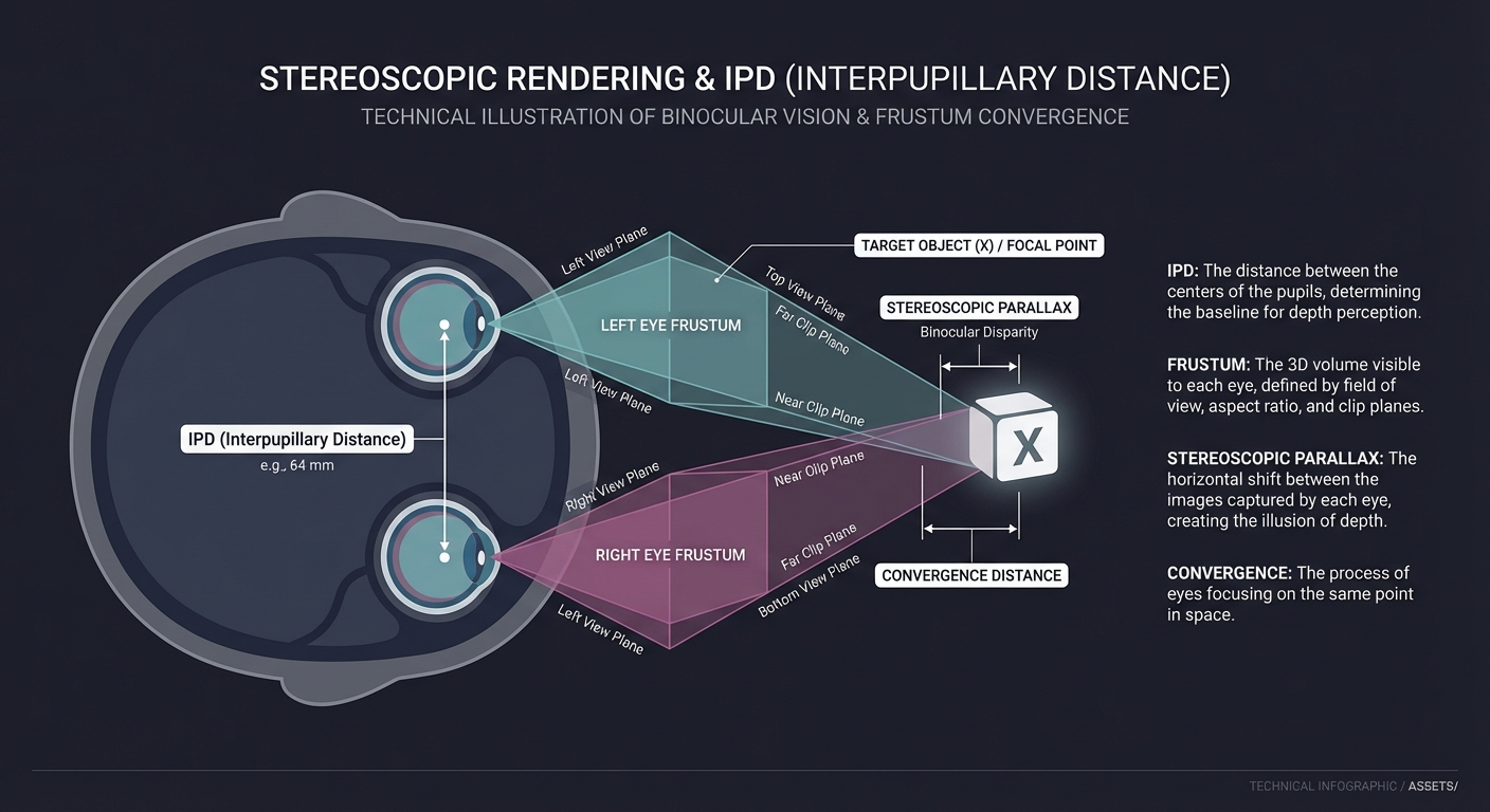
Key insight: You aren’t just drawing the scene twice. You are creating two distinct viewing frustums. If the IPD is wrong, the world feels too big (giantism) or too small (miniaturization).
5. Latency & Asynchronous Timewarp (ATW)
In XR, “Motion-to-Photon” latency must be under 20ms. If a frame takes too long to render, the headset “warps” the previous frame based on the very latest head movement to prevent stutter.
    Frame N (Rendered at T=0)
    [  Old Pose  ]
          |
    Delay (Head moved 5 degrees)
          |
    [ New Pose ] ----> [ Apply Homography/Warp ] ----> [ Displayed Frame ]
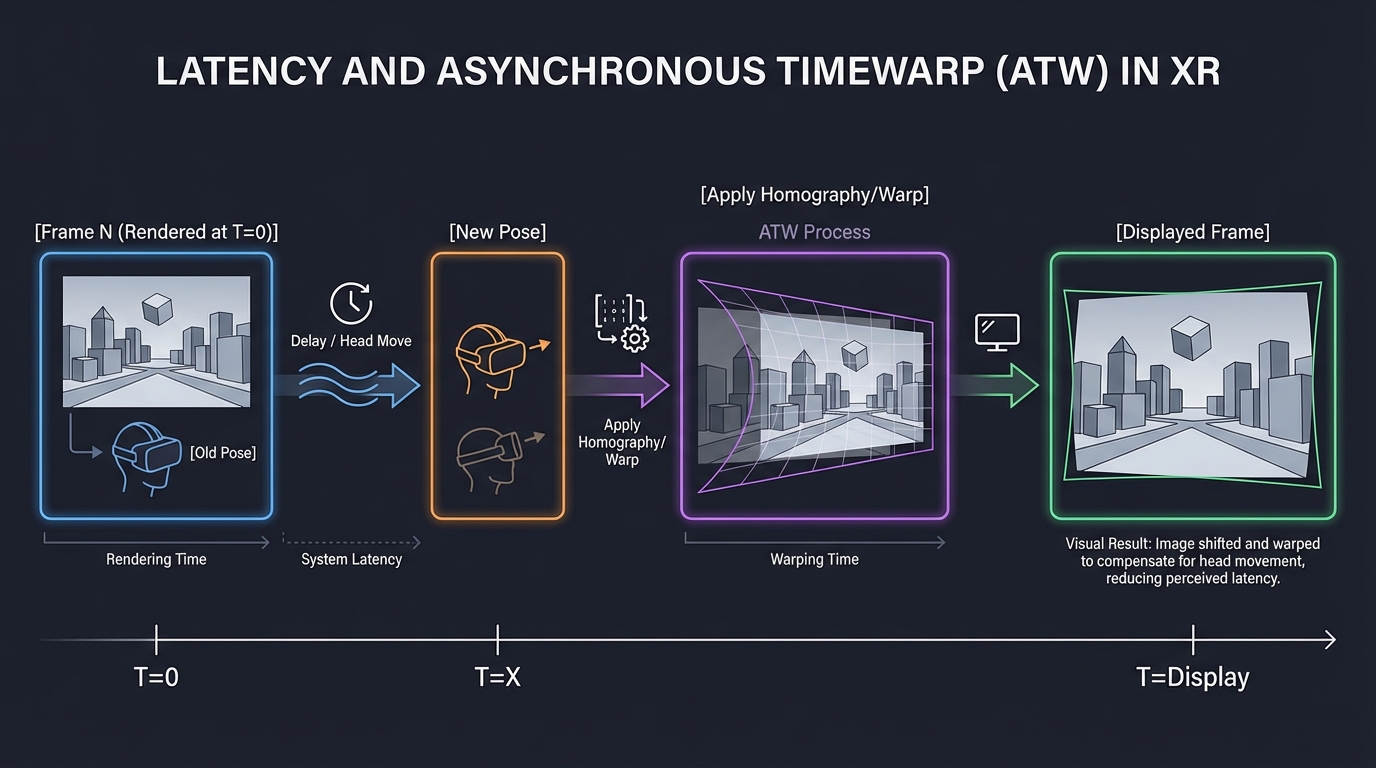
Key insight: This is a “cheat” that hides slow rendering. By re-projecting the 2D image using a 3x3 Homography matrix, we can maintain 90FPS visual stability even if the game only renders at 45FPS.
6. Spatial Audio & HRTF
Sound reaches each ear at different times (ITD) and different intensities (ILD), and is filtered by your ear shape (HRTF). This is how you know a sound is “behind” you.
           Sound Source (S)
              /     \
             /       \
       Ear L (T1)   Ear R (T2)
        (Filtered)   (Filtered)
             \       /
           [Brain Processes] -> "It's 30 degrees to the left!"
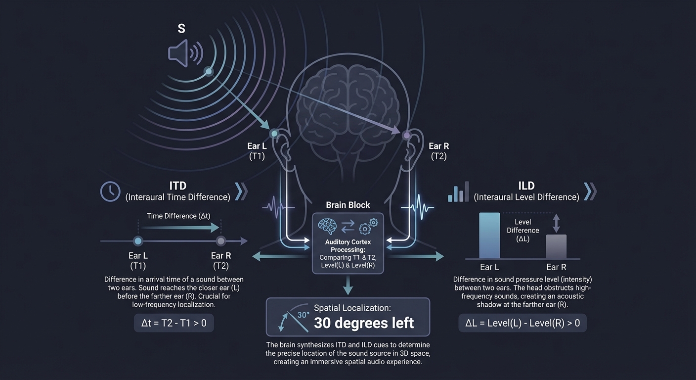
Key insight: Spatial audio is what truly anchors a digital object. If you see a virtual robot but its sound comes from your stereo headphones without filtering, the illusion of “presence” is broken.
Tools for Seeing the Spatial World
You can’t master what you can’t observe. These tools make the invisible math visible:
1. The Spectator View
Most XR SDKs allow you to see the “Head” and “Frustum” from a 3rd person perspective. This is critical for debugging SLAM drift.
2. Shader Toy & GLSL
For Project 11 (Edge Detection), using tools like ShaderToy helps you visualize image kernels in real-time.
3. OpenCV / MediaPipe
Essential for testing feature detection (Project 6) and hand tracking (Project 3) on your laptop before moving to a headset.
4. Unity/Unreal Frame Debugger
Even if we build from scratch, seeing how professional engines batch their draw calls and handle stereo rendering is invaluable.
Concept Summary Table
| Concept Cluster | What You Need to Internalize |
|---|---|
| Linear Algebra | Matrices and Quaternions are the language of 3D motion. Avoid Gimbal Lock. |
| Perspective Projection | How 3D volumes (Frustums) are flattened into 2D viewing planes. |
| Tracking & SLAM | Converting raw sensor data (IMU/Camera) into a stable pose $(x,y,z, r,p,y)$. |
| Spatial UI/UX | Throwing out “buttons” for affordances, gaze-targeting, and hand-physics. |
| Presence & Comfort | Balancing frame rates, field-of-view, and sensory input to maintain the illusion. |
| Spatial Audio | Using HRTF and acoustic modeling to anchor digital objects with sound. |
Deep Dive Reading by Concept
Foundation: 3D Graphics & Math
| Concept | Book & Chapter |
|---|---|
| Matrix Transformations | “Computer Graphics from Scratch” by Gabriel Gambetta — Ch. 3-5 |
| 3D Rendering Pipeline | “Real-Time Rendering” by Akenine-Möller — Ch. 2 |
| Quaternions Mastery | “3D Math Primer for Graphics and Game Development” by Fletcher Dunn — Ch. 8 |
Spatial Awareness & Tracking
| Concept | Book & Chapter |
|---|---|
| Computer Vision (SLAM) | “Multiple View Geometry in Computer Vision” by Hartley & Zisserman — Ch. 1-2 |
| SLAM Fundamentals | “SLAM Handbook” by Carlone et al. — Ch. 1: Introduction |
| Feature Extraction | “Learning OpenCV” by Gary Bradski — Ch. 11-12 |
Latency, Performance & Humans
| Concept | Book & Chapter |
|---|---|
| Stereo & VR Optics | “Real-Time Rendering” by Akenine-Möller — Ch. 21 |
| Human Interface | “The Design of Everyday Things” by Don Norman (Applied to 3D Space) |
| Asynchronous Timewarp | “The Asynchronous Time Warp for Virtual Reality” by J. M. P. van Waveren |
Spatial Audio & Interaction
| Concept | Book & Chapter |
|---|---|
| Binaural Playback | “Spatial Sound: Principles and Applications” by Bosun Xie — Ch. 5 |
| Spatial Audio Basics | “Spatial Audio” by Francis Rumsey — Ch. 1-2 |
| Landmark Detection | “Learning OpenCV” by Gary Bradski — Ch. 13 |
Project 1: The First-Principles 3D Engine (Wireframe)
What you’ll build: A program that takes a list of 3D vertices (a cube or pyramid) and renders them as a wireframe on a 2D screen, allowing you to rotate, scale, and move the object using matrix multiplications.
Real World Outcome
A C application that opens a window and renders a wireframe cube. Users can use arrow keys to rotate the cube in real-time. You’ll see the cube “distort” correctly as it gets closer to the camera, proving your perspective math works. You’ll be able to toggle between “Parallel” and “Perspective” modes to see the difference.
Example Output:
$ ./wireframe_engine --model cube.obj
[System] SDL2 Initialized: 800x600 Window Created.
[Engine] Loading 8 vertices, 12 edges from cube.obj.
[Math] Projection Matrix Initialized:
  [ 1.73  0.00  0.00  0.00 ]
  [ 0.00  2.31  0.00  0.00 ]
  [ 0.00  0.00 -1.02 -2.02 ]
  [ 0.00  0.00 -1.00  0.00 ]
[Loop] Frame 142: FPS: 60 | Rotation(Yaw: 1.2, Pitch: 0.5)
# You are seeing the birth of a graphics engine!
The Core Question You’re Answering
“How do we mathematically flatten a 3D world onto a 2D array of pixels without losing the sense of depth?”
Concepts You Must Understand First
- Homogeneous Coordinates: Why do we use 4D vectors $(x, y, z, w)$ for 3D points?
- The Graphics Pipeline: The journey from a vertex in local space to a pixel on the screen.
- Perspective Divide: Why dividing by the W-component (or Z) creates the illusion of distance.
- Matrices as Transforms: How a matrix can represent “Rotation,” “Scale,” and “Translation” simultaneously.
Questions to Guide Your Design
- How does the Field of View (FOV) affect the values in your projection matrix?
- What happens to the math when an object is exactly at Z=0 (the camera plane)?
- How do you handle the aspect ratio so your cube doesn’t look stretched on wide screens?
Thinking Exercise
Draw a square on paper. Now draw a cube. Notice how you “projected” the 3D cube onto the 2D paper. What rules did your brain follow? (Parallel lines, vanishing points). If you moved your head closer to the paper, would your drawing change?
The Interview Questions They’ll Ask
- “Explain the difference between Orthographic and Perspective projection.”
- “What is the purpose of the ‘W’ component in a 4D vector?”
- “How do you handle clipping for objects partially behind the camera?”
Hints in Layers
- Layer 1: Start with printf. Print the (x, y) coordinates of your projected vertices to the console before trying to draw them.
- Layer 2: Simple Divide. Use
x' = x / zandy' = y / z. This is the simplest projection but lacks FOV control. - Layer 3: The 4x4 Matrix. Implement a full
multiply(Vector, Matrix)function. This allows you to chain rotations. - Layer 4: SDL2/Line Drawing. Use
SDL_RenderDrawLineto connect the projected 2D points.
Books That Will Help
| Topic | Book | Chapter | |——-|——|———| | 3D Projection | “Computer Graphics from Scratch” | Ch. 9-10 | | Matrix Math | “3D Math Primer for Graphics and Game Development” | Ch. 6-9 | | SDL2 Rendering | “A Tour of C++” (for concepts) / SDL2 Documentation | - |
Project 2: Stereoscopic “Split-Screen” Renderer (The VR Vision)
What you’ll build: An extension of Project 1 that renders two views of the same 3D scene side-by-side, offset by an “Interpupillary Distance” (IPD).
Real World Outcome
A C++ application rendering two distinct viewports (Left Eye / Right Eye) on a single window. When you look at this through a mobile VR headset (like Google Cardboard) or use the “cross-eye” method, the wireframe object will pop out in 3D. You can adjust the IPD in real-time with the + and - keys.
Example Output:
$ ./stereo_renderer --ipd 0.064
[VR] IPD set to 64mm (Human Average).
[Render] Split-Screen Mode:
  - Left Viewport: [0, 0, 400, 600]
  - Right Viewport: [400, 0, 400, 600]
[Math] Camera L: pos(-0.032, 0, 0) | Camera R: pos(0.032, 0, 0)
[Math] Notice: Projection matrices are slightly shifted (Asymmetric Frustum).
The Core Question You’re Answering
“How do we simulate the human brain’s depth perception by manipulating two virtual cameras?”
Concepts You Must Understand First
- Binocular Parallax: The difference in image location of an object seen by the left and right eyes.
- Interpupillary Distance (IPD): Why 64mm is the “magic number” for humans.
- Asymmetric Frustums: Why the two eyes don’t just use the same projection matrix with an offset (this causes vertical parallax/nausea).
Questions to Guide Your Design
- Should the two cameras be parallel or angled towards each other (toed-in)? (Hint: Toed-in is a common mistake).
- How do you prevent “Vertical Parallax” which causes instant headache?
- How does changing the IPD in software change the perceived scale of the world? (Try setting IPD to 1 meter).
Thinking Exercise
Hold your thumb in front of your face. Close one eye, then the other. Notice the thumb “jumps.” Measure that jump. Now look at a tree far away and repeat. The jump is smaller. That is the parallax your engine must recreate.
The Interview Questions They’ll Ask
- “What is the Vergence-Accommodation Conflict (VAC)?”
- “Why is ‘Toe-in’ rendering considered bad for VR compared to parallel cameras with asymmetric frustums?”
- “How does IPD affect the perceived scale of the world?”
Hints in Layers
- Layer 1: Double Render. Just render the same scene twice side-by-side. It will look identical and feel “flat.”
- Layer 2: Parallel Offset. Offset the cameras horizontally by +/- IPD/2. You’ll see depth, but the edges will look “wrong.”
- Layer 3: Asymmetric Projection. Modify the projection matrix so the “center” of the frustum is offset. This is how the Rift and Quest work.
Books That Will Help
| Topic | Book | Chapter | |——-|——|———| | Stereo Rendering | “Real-Time Rendering” | Ch. 21 | | Human Vision | “3D Math Primer for Graphics and Game Development” | Ch. 15 |
Project 3: The “Invisible Mouse” (Hand Tracking Input)
What you’ll build: A Python application that uses your webcam to track your hand. Moving your index finger moves the OS mouse cursor, and “pinching” (thumb + index) triggers a click.
Real World Outcome
A tool that allows you to control your computer without touching it. You’ll see a video feed with a 21-point hand skeleton overlayed. You’ll be able to “paint” in Microsoft Paint just by waving your finger in the air.
Example Output:
$ python hand_mouse.py --smoothing 0.5
[CV] Camera Initialized: 640x480 @ 30fps.
[MediaPipe] Hand detected (Confidence: 0.98)
[Input] Index Tip: (0.521, 0.432) -> Desktop Pos: (1000, 466)
[Action] THUMB-INDEX DISTANCE: 0.02 -> PINCH DETECTED!
[System] Triggering Mouse Down at (1000, 466).
The Core Question You’re Answering
“How do we map a non-linear, noisy 3D input (a hand) to a precise 2D interface (a desktop)?”
Concepts You Must Understand First
- Landmark Estimation: How a Neural Network (like MediaPipe) identifies specific joints (PIP, DIP, MCP).
- Jitter Reduction (Filtering): Why raw coordinates from a camera are too shaky for a mouse and how to fix it with a “One Euro Filter” or “Moving Average.”
- Coordinate Mapping: Converting normalized (0.0 to 1.0) camera space to pixel (0 to 1920) screen space.
Questions to Guide Your Design
- How do you distinguish between “moving the mouse” and “getting ready to click”?
- What happens when your hand leaves the camera’s field of view? Does the mouse jump to (0,0)?
- What is the ideal “smoothing” factor to balance responsiveness (low latency) and stability (no shaking)?
Thinking Exercise
Try to draw a perfect circle in the air with your finger. Now watch a recording of it. It’s likely very shaky. Your hand is not a mouse; it’s a living limb. How would you write an algorithm that “guesses” your intent despite the noise?
The Interview Questions They’ll Ask
- “How do you handle occlusion (e.g., when the thumb is behind the palm)?”
- “What is the latency cost of using a neural network for hand tracking?”
- “Explain how a Kalman filter works in the context of tracking.”
Hints in Layers
- Layer 1: Raw Landmark. Use MediaPipe to get the (x, y) of the index finger tip and print it.
- Layer 2: Screen Mapping. Use
pyautoguito move the mouse to those coordinates. - Layer 3: Smoothing. Implement a simple moving average:
pos = (prev_pos * 0.8) + (new_pos * 0.2). - Layer 4: Gesture Logic. Calculate the Euclidean distance between landmark 4 (thumb tip) and 8 (index tip). If distance < 0.05, it’s a click.
Books That Will Help
| Topic | Book | Chapter | |——-|——|———| | Computer Vision | “Learning OpenCV” | Ch. 13-14 | | Interaction Design | “The Design of Everyday Things” | Ch. 1-2 | | Signal Processing | “Computer Systems: A Programmer’s Perspective” | (Filtering concepts) |
Project 4: The WebXR “Portal” (Augmented Reality)
What you’ll build: A web application where you point your phone at the floor, a 3D door appears, and you can physically walk “into” it to enter a different virtual world.
Real World Outcome
A website that works on Chrome for Android or the WebXR Viewer on iOS. When you open the URL, your camera feed appears. Tapping the floor places a “Magic Door.” As you physically walk toward the door and “pass through” it, the real world (camera feed) is replaced by a high-fidelity virtual forest. Turning around, you see the door behind you, showing your real room on the other side.
Example Output:
// WebXR Session Console Output
[WebXR] Session Started: immersive-ar
[SLAM] Surface Found: Plane ID 12 (Horizontal, Floor)
[HitTest] User tap at screen(0.5, 0.8) -> World(1.2, -1.5, -3.0)
[Scene] Portal Anchor placed. Virtual world pre-rendered to offscreen buffer.
[Stencil] Masking virtual world pixels to Portal Frame geometry.
# You just created a hole in reality!
The Core Question You’re Answering
“How do we synchronize a virtual coordinate system with the physical world using only a browser and a phone camera?”
Concepts You Must Understand First
- Hit Testing: How to cast a ray from a 2D touch point into the 3D reconstructed model of the room.
- Spatial Anchors: Why virtual objects need to be “pinned” to specific real-world feature points to prevent “drift.”
- Stencil Buffers: The graphics trick used to make a 3D scene visible ONLY through a specific 2D shape (the portal frame).
- WebXR API: The standard for accessing AR/VR hardware through a browser.
Questions to Guide Your Design
- How does the phone know it has moved 1 meter forward? (Hint: Visual-Inertial Odometry).
- Why does the portal “drift” if you move too fast or in a dark room?
- How do you handle the transition when the user’s camera physically crosses the portal plane?
Thinking Exercise
Look at a specific tile on your floor. Walk around it. Your brain uses “features” (cracks, colors, patterns) to keep that tile in place. How does a computer find those same features in a pixel array? What happens if the floor is a solid, shiny white color?
The Interview Questions They’ll Ask
- “What is the difference between ARKit/ARCore and the WebXR standard?”
- “How does hit-testing work in an AR session?”
- “Explain the ‘Stencil Buffer’ technique used to create the portal effect.”
Hints in Layers
- Layer 1: Hello WebXR. Get a basic Three.js scene running in AR mode using
navigator.xr. - Layer 2: Floor Detection. Use the
hit-testAPI to find the floor and place a simple 3D cube there. - Layer 3: The Frame. Replace the cube with a door frame.
- Layer 4: The Magic. Set the portal interior to
stencilWrite: true. Render the virtual world only where the stencil value matches the door frame.
Books That Will Help
| Topic | Book | Chapter | |——-|——|———| | WebGL/Three.js | “Computer Graphics from Scratch” | Ch. 1-3 | | AR Fundamentals | “Real-Time Rendering” | Ch. 21 | | AR Computer Vision | “Multiple View Geometry in Computer Vision” | Ch. 1 |
Project 5: The “Look to Select” Menu (Spatial UI/UX)
What you’ll build: A VR scene with floating 3D buttons. A reticle in the center of your vision acts as your cursor. Staying on a button for 2 seconds triggers a selection.
Real World Outcome
A VR interface where your “gaze” is the mouse. As you look at different 3D spheres floating in space, they pulse or change color to acknowledge your focus. A “loading ring” fills up around your reticle as you dwell on a button. Once full, a spatial “click” sound plays, and a new sub-menu opens. This is the foundation of “hands-free” XR interfaces.
Example Output:
[UI] Gaze entered 'Settings' button (ID: 0x44).
[Timer] Dwell detected. Starting 2000ms countdown.
[Anim] Scaling button up 1.1x. Progress: 25%... 50%... 75%...
[Action] Selection Confirmed! Triggering event: OPEN_SETTINGS.
[Audio] Play 'select.wav' at WorldPos(0.0, 1.5, -2.0) with reverb.
The Core Question You’re Answering
“How do we design interfaces for a world where ‘pointing and clicking’ is replaced by ‘looking and being’?”
Concepts You Must Understand First
- Raycasting: Shooting an invisible line from the camera’s forward vector to detect collisions with 3D UI objects.
- Dwell Time: The “confirmation delay” used to avoid the “Midas Touch” (accidental clicks everywhere you look).
- Fitts’s Law in 3D: How the size and distance of a target affect the speed and accuracy of selection.
- Visual Affordances: Using “Hover” states (glow, scale, sound) to tell the user an object is interactive.
Questions to Guide Your Design
- How long should the “dwell time” be? Is 1 second too fast? Is 3 seconds too boring?
- Where should UI be placed in 3D space to avoid “gorilla arm” (if using hands) or neck strain (if using gaze)?
- How do you provide feedback that a selection is in progress vs. completed?
Thinking Exercise
Sit in a chair and look at objects around the room. Notice how your eyes “dart” (saccades) rather than move smoothly. Now try to keep your eyes perfectly still on one point. It’s hard! How does this biological reality affect a UI that relies on your gaze?
The Interview Questions They’ll Ask
- “What is the ‘Midas Touch’ problem in gaze-based interaction?”
- “How do you handle UI depth to avoid eye strain (Vergence-Accommodation Conflict)?”
- “What are the pros and cons of Gaze vs. Hand Controller vs. Hand Tracking interaction?”
Hints in Layers
- Layer 1: The Ray. Every frame, cast a ray from the center of the camera. Log the name of any object it hits.
- Layer 2: The State. Create a
Buttonclass with states:Idle,Hover,Dwell,Selected. - Layer 3: The Progress Bar. Draw a circular ring (a donut geometry) that “fills” by increasing its arc length over time.
- Layer 4: Sound. Add
SpatialAudioSourceto the button so the feedback feels like it’s coming from the object itself.
Books That Will Help
| Topic | Book | Chapter | |——-|——|———| | Design Principles | “The Design of Everyday Things” | Ch. 3-4 | | Spatial UI | “Real-Time Rendering” | Ch. 22 | | Human Factors | “3D Math Primer for Graphics and Game Development” | Ch. 15 |
Project 6: Mini-SLAM (Tracking from Video)
What you’ll build: A Python script that processes a video file, detects unique “features” (corners/dots), and calculates a 3D path $(x, y, z)$ showing how the camera moved through the room.
Real World Outcome
A visualization where one window shows the raw video feed with colorful dots on every corner of your furniture. Another window shows a 3D “top-down” map where a little camera icon moves as you walk. You are essentially building the “Brain” of a Quest or Vision Pro headset using raw pixels.
Example Output:
$ python mini_slam.py --video room_walk.mp4 --algo ORB
[SLAM] Frame 1: Detected 500 features.
[SLAM] Frame 2: 320 matches found. Inliers: 280.
[Math] Essential Matrix computed.
[Map] Relative Motion: [X: +0.02m, Y: -0.01m, Z: +0.05m]
[Map] Total Path Length: 4.2 meters.
# You are reconstructing 3D space from a 2D lie!
The Core Question You’re Answering
“How can a machine reconstruct its own movement and the structure of the room using only a stream of 2D images?”
Concepts You Must Understand First
- Feature Detection (ORB/FAST): Identifying unique, trackable points (corners, high-contrast blobs) in an image.
- Descriptor Matching: Using math to prove that the “dot” in Frame 1 is the same physical object as the “dot” in Frame 2.
- Epipolar Geometry: The relationship between two camera views of the same scene.
- Structure from Motion (SfM): The process of estimating 3D structures from 2D image sequences.
Questions to Guide Your Design
- Why do we need at least two different camera views to calculate depth?
- What happens to SLAM when the camera sees a mirror, a blank white wall, or a moving dog?
- How do you filter out “outliers” (incorrectly matched points) that would ruin your pose calculation? (Hint: RANSAC).
Thinking Exercise
Close one eye and move your head side to side. Notice how objects close to you move “faster” across your vision than objects far away. This is “Motion Parallax.” How would you turn that speed difference into a precise distance measurement in centimeters?
The Interview Questions They’ll Ask
- “What is the difference between Feature-based SLAM and Direct SLAM?”
- “Explain the ‘Loop Closure’ problem and why it’s critical for long-term tracking.”
- “What is ‘Bundle Adjustment’ and why is it the most computationally expensive part of SLAM?”
Hints in Layers
- Layer 1: Feature Hunt. Use
cv2.ORB_create()to find points andcv2.drawKeypoints()to see them. - Layer 2: Tracking. Use a “Brute Force Matcher” or “FLANN” to connect points between Frame N and Frame N+1.
- Layer 3: The Pose. Use
cv2.findEssentialMat()andcv2.recoverPose()to get the (R)otation and (T)ranslation matrices. - Layer 4: Point Cloud. Use triangulation to turn matched 2D points into 3D points $(X, Y, Z)$ and plot them.
Books That Will Help
| Topic | Book | Chapter | |——-|——|———| | SLAM Math | “Multiple View Geometry in Computer Vision” | Ch. 9-12 | | Implementation | “Learning OpenCV” | Ch. 11-12 | | Vision Theory | “Computer Vision: Algorithms and Applications” | Ch. 7 |
Project 7: The Room Scanner (Voxel Reconstruction)
What you’ll build: A tool that takes a depth map (from a phone’s LiDAR or a depth camera) and integrates it into a 3D “Voxel” grid (like Minecraft blocks) to reconstruct the room’s geometry.
Real World Outcome
A 3D model of your actual room that you can export as a .obj file. As you move your phone around, you’ll see a 3D “ghost” of your furniture appearing on the screen. The points will gradually “solidify” into a continuous triangle mesh that you could theoretically import into Blender or a game engine.
Example Output:
$ ./room_scanner --source lidar --resolution 0.05
[LiDAR] Active. Streaming 30k points/sec at 5m range.
[Voxel] Grid Initialized: 10m x 10m x 4m. Voxel size: 5cm.
[TSDF] Integrating Frame 45: 2,100 voxels updated.
[Mesh] Running Marching Cubes... Generated 45,000 triangles.
[Export] File saved: my_living_room.obj
# You just digitized your physical reality!
The Core Question You’re Answering
“How do we turn a series of noisy depth points into a continuous, solid 3D surface?”
Concepts You Must Understand First
- Voxels vs. Point Clouds: Why a grid of “occupancy” is better for surface reconstruction than just a list of raw points.
- TSDF (Truncated Signed Distance Function): The standard math for merging multiple noisy depth scans into a smooth surface.
- Marching Cubes Algorithm: The algorithm that converts a grid of density values into a triangle mesh.
- Spatial Hashing: How to store a giant room in memory without using a 100GB 3D array.
Questions to Guide Your Design
- How do you handle moving objects (like a person walking by) during a scan? (Hint: Outlier rejection).
- What happens to your memory usage as you move from scanning a chair to scanning a whole house?
- How do you “smooth” out the jittery noise from a low-cost LiDAR sensor?
Thinking Exercise
Imagine you have a giant 3D grid of small translucent boxes. For every point your sensor hits, you mark a box as “more solid.” If you hit it multiple times from different angles, you are “sure” it’s a wall. How would you represent “uncertainty” or “empty space” in this grid?
The Interview Questions They’ll Ask
- “What is a TSDF and why is it preferred over raw point integration for AR?”
- “Explain how the Marching Cubes algorithm works at a high level.”
- “How does a ‘Global Loop Closure’ in SLAM affect an already reconstructed mesh?”
Hints in Layers
- Layer 1: Point Cloud. Just draw every depth point as a tiny 3D pixel (gl_PointSize).
- Layer 2: Occupancy Grid. Create a fixed 3D array. If a point falls in a cell, increment its value.
- Layer 3: TSDF. For each voxel, store the distance to the nearest point. Positive if in front, negative if behind.
- Layer 4: Meshing. Use a library implementation of Marching Cubes to turn the TSDF values into triangles.
Books That Will Help
| Topic | Book | Chapter | |——-|——|———| | 3D Reconstruction | “Computer Vision: Algorithms and Applications” | Ch. 12 | | Surface Mesh | “Real-Time Rendering” | Ch. 16 | | Geometric Math | “3D Math Primer for Graphics and Game Development” | Ch. 13 |
Project 8: The Spatial Audio Engine (3D Sound)
What you’ll build: A C++ audio processor that takes a mono sound file and a 3D position, and outputs a stereo signal that makes the sound seem to come from that specific physical location through headphones.
Real World Outcome
A program where you can move a “sound source” around your head using your mouse on a 2D map. Through headphones, you can clearly hear the sound moving behind your left ear, then above your head, then distantly to your right. You are simulating how the human ear actually hears the world.
Example Output:
$ ./spatial_audio --source drone_hum.wav --hrtf MIT_KEMAR.bin
[Audio] Source: drone_hum.wav (44.1kHz Mono)
[Pos] Moving source to (x: 1.5, y: 1.0, z: -2.0)
[DSP] Calculated Azimuth: 140°, Elevation: 20°.
[DSP] Applying HRTF Filter Pair #88...
[System] Outputting Stereo Binaural Stream.
# Your ears are being lied to by a filter!
The Core Question You’re Answering
“How does a brain perceive sound location using only two ears, and how do we trick it mathematically?”
Concepts You Must Understand First
- HRTF (Head-Related Transfer Function): The complex frequency filter created by your unique ear shape, head size, and shoulders.
- ITD (Interaural Time Difference): The 10-20 microsecond delay between sound hitting one ear vs. the other.
- Convolution: The mathematical process of applying a room’s “impulse response” or an HRTF filter to a dry audio signal.
- Inverse Square Law: How volume decreases with distance.
Questions to Guide Your Design
- Why does a sound directly in front of you sound almost the same as a sound directly behind you in a simple model? (The “Cone of Confusion”).
- How do you handle “Head Tracking”? If the user turns their head 90 degrees left, the sound should stay at the same “world” position (meaning it moves to the right relative to the head).
- How do you simulate “reverb” to make the sound feel like it’s in a specific room vs. an open field?
Thinking Exercise
Close your eyes. Have a friend snap their fingers in different places. Notice how you can tell where it is. Is it the volume? The timing? The “muffled” quality if it’s behind you? Now try to describe that “muffled” quality as a Low-Pass filter.
The Interview Questions They’ll Ask
- “What is the ‘Cone of Confusion’ and how do HRTFs help solve it?”
- “Explain the difference between Panning (stereo) and Binaural Synthesis.”
- “How would you optimize HRTF convolution for a high number (50+) of sound sources?”
Hints in Layers
- Layer 1: Stereo Pan. Just change the Left/Right volume based on the angle. (Sounds like a 1970s record).
- Layer 2: ITD. Introduce a tiny sample delay (e.g., 20 samples) to the “far” ear. Notice how it feels more “directional.”
- Layer 3: HRTF Convolution. Load an HRTF dataset (like CIPIC or MIT). Perform an FFT convolution of the mono audio with the filter for the specific angle.
Books That Will Help
| Topic | Book | Chapter | |——-|——|———| | Psychoacoustics | “Spatial Audio” | Ch. 2 | | Binaural Principles | “Spatial Sound: Principles and Applications” | Ch. 5 | | DSP Basics | “Computer Systems: A Programmer’s Perspective” | (Floating point/Audio concepts) |
Project 9: The “Timewarp” Simulator (Latency Fixer)
What you’ll build: A C++ tool that simulates a “late” frame and applies a mathematical warp (Homography) to adjust it to the user’s latest head orientation before it hits the display.
Real World Outcome
A side-by-side visualization. On the left, a scene with 100ms of lag (it feels nauseating). On the right, the same laggy scene but with “Timewarp” active. Even if the objects in the scene are lagging, the world stays perfectly “stuck” to your head movement. This is why you don’t get sick in a Quest 3 even during lag spikes.
Example Output:
$ ./timewarp_sim --engine_fps 30 --display_hz 90
[Engine] Frame #4 rendered at T+33ms. Pose: [Yaw: 10.0]
[Display] Scanout at T+40ms. Current IMU Pose: [Yaw: 11.2]
[Warp] DELTA: 1.2 degrees. Calculating 3x3 Homography Matrix.
[GPU] Warping 4K texture... Done in 0.5ms.
[Result] Perceived Jitter: 0.02 pixels (Virtual Stability achieved).
The Core Question You’re Answering
“How do we maintain a stable virtual world when the computer is too slow to keep up with the speed of human head movement?”
Concepts You Must Understand First
- Rotational Reprojection: Moving every pixel in a 2D image to compensate for a new 3D rotation.
- Homography Matrices: The 3x3 matrix that maps one 2D perspective (plane) to another.
- Motion-to-Photon Latency: The critical metric (needs to be < 20ms) for XR comfort.
- Display Persistence: Why keeping pixels on for too long causes “blur” and how low-persistence displays work.
Questions to Guide Your Design
- If the user moves their head too far between the render and the warp, what appears at the edges of the screen? (Hint: Black bars/vignetting).
- Why is Timewarp perfect for “rotation” (looking around) but very hard for “translation” (walking)?
- How do you implement this as a “post-processing” shader pass?
Thinking Exercise
Take a high-res photo with your phone. Now look at it in full screen. If you rotate your phone 5 degrees, you have to shift the photo in the opposite direction on the screen to make it feel like the photo is “staying still” in the real world. That is Timewarp.
The Interview Questions They’ll Ask
- “What is Asynchronous Timewarp (ATW) vs. SpaceWarp (ASW)?”
- “What is the ‘Black Smear’ artifact and how does it relate to OLED display persistence?”
- “Why does Timewarp not solve the problem of objects moving inside the scene (e.g., a car driving by)?”
Hints in Layers
- Layer 1: 2D Shift. Simply shift an image left/right based on a mouse movement.
- Layer 2: 3D Rotation. Use a 3D rotation matrix to rotate the camera and see the view change.
- Layer 3: The Delta. Render a scene, wait 100ms, rotate the camera, then use a Homography to “fix” the old frame to the new rotation.
- Layer 4: Shader. Port the Homography math to a GLSL fragment shader for real-time performance.
Books That Will Help
| Topic | Book | Chapter | |——-|——|———| | Reprojection | “Real-Time Rendering” | Ch. 21 | | Homography Math | “Multiple View Geometry in Computer Vision” | Ch. 2 | | GPU Performance | “Real-Time Rendering” | Ch. 3 |
Project 10: Persistent World State (Multiplayer AR)
What you’ll build: A system where two people on two different phones can see the same 3D object on the same real-world table, synchronized in real-time.
Real World Outcome
Two users standing around the same physical coffee table. User A places a virtual chess piece on the table. User B instantly sees that piece on their own phone, in the exact same physical spot. If User A slides the piece 10cm to the left, User B sees it move in real-time. This is the foundation of collaborative spatial work.
Example Output:
[Network] Joined Session: 'LivingRoom_Chess_01'
[SLAM] Localizing to Shared Anchor... Success (Confidence 0.94).
[Sync] Anchor Root: World(0,0,0) mapped to Feature_Cloud_ID: 8812.
[State] Received Update: 'BlackQueen' pos(0.12, 0.75, -0.44).
[Render] Visual offset between users: < 5mm.
# You just synchronized two different realities!
The Core Question You’re Answering
“How do we create a shared ‘reality’ across different devices that have different internal coordinate systems?”
Concepts You Must Understand First
- Spatial Anchors: Cloud-stored feature points (a “fingerprint” of a room) that allow multiple devices to find the same (0,0,0) point.
- Coordinate Space Transformation: Converting Device A’s local space to “Anchor Space,” and then from “Anchor Space” to Device B’s local space.
- Network Synchronization: Using WebSockets or UDP (with prediction/interpolation) to keep object positions consistent under high latency.
- Relocalization: The process of a device “recognizing” a room it has seen before.
Questions to Guide Your Design
- How do you handle “drift”? What if User A’s phone thinks the table is 1cm higher than User B’s phone does?
- What is the “Root Anchor” of your world? Is it a QR code, a specific poster on the wall, or a 3D scan of the furniture?
- How do you handle “Late Joiners”? If a third person joins the room 5 minutes late, how do they get the current state of all objects?
Thinking Exercise
Imagine you and a friend are in a pitch-black room with only flashlights. How do you agree on where the “center” of the room is without a measuring tape? You would probably find a specific landmark, like a light switch or a door handle, and say “Okay, that’s our (0,0,0).” This is exactly how Spatial Anchors work.
The Interview Questions They’ll Ask
- “What is a ‘Cloud Anchor’ and how does it differ from a local SLAM anchor?”
- “How would you handle latency compensation in a multiplayer AR game so objects don’t ‘teleport’?”
- “Explain the mathematical process of transforming a coordinate from one user’s local space to another’s.”
Hints in Layers
- Layer 1: Simple Sync. Build a 2D web app where two users move a dot on a screen. Use Socket.io.
- Layer 2: The QR Anchor. Have both AR users scan the same physical QR code. Use that code’s position as (0,0,0). Sync coordinates relative to that.
- Layer 3: Feature Sync. Use an SDK like ARCore Cloud Anchors or Azure Spatial Anchors to sync based on the actual 3D features of the room.
- Layer 4: Interpolation. Don’t just set the position; use
lerp(old_pos, new_pos, alpha)to make the movement look smooth despite network jitter.
Books That Will Help
| Topic | Book | Chapter | |——-|——|———| | Shared Spaces | “The Design of Everyday Things” | Ch. 6 | | Networking | “Real-Time Rendering” | Ch. 19 | | Multiplayer Logic | “Computer Systems: A Programmer’s Perspective” | (Networking concepts) |
Project 11: Pass-through Edge Detection (Mixed Reality)
What you’ll build: A “Mixed Reality” filter that takes the real-world camera feed (pass-through) and applies a real-time edge detection filter (Canny edge) to see the world like a glowing blueprint.
Real World Outcome
You put on a headset or look through your phone, and your entire room is transformed into a “Matrix-style” wireframe. Every wall, chair, and person is outlined in neon green glowing lines. This demonstrates how we can bridge the gap between “Real” pixels and “Virtual” geometry.
Example Output:
$ ./mr_filter --effect canny --color #00FF00
[Camera] Pass-through: 1920x1080 @ 60fps.
[GPU] Converting to Grayscale...
[GPU] Sobel Gradients (X, Y) computed.
[GPU] Non-maximum Suppression...
[Shader] Edge detected at (x:450, y:220). Pixel color -> Neon Green.
[Display] Latency: 4ms. (Zero-perceived lag).
# You are seeing the 'skeleton' of the world!
The Core Question You’re Answering
“How do we manipulate the real-time perception of physical reality through computer vision shaders?”
Concepts You Must Understand First
- Image Convolution Kernels: How small matrices (like Sobel or Prewitt) can find gradients (edges) in an image.
- Canny Edge Detection: The 5-stage algorithm (Noise reduction -> Gradient -> Non-max suppression -> Hysteresis) for high-quality edges.
- GPU Shaders (GLSL/HLSL): How to run heavy image processing at 90+ FPS by parallelizing the work across thousands of cores.
- Alpha Blending: How to mix the virtual edges with the original camera feed.
Questions to Guide Your Design
- Why does edge detection look “noisy” (snowy) in dark rooms? How can you fix it? (Hint: Gaussian Blur).
- How do you handle latency? If the edge detection takes 30ms, the glowing lines will “lag” behind the real objects as you move your head.
- How do you “re-project” the camera frames to match the user’s eye position (Asymmetric Pass-through)?
Thinking Exercise
Look at the corner of your desk. What makes it an “edge” to your brain? It’s the sudden jump in brightness or color. If you were a computer, how would you find that “jump” in a grid of numbers? (Hint: Subtraction).
The Interview Questions They’ll Ask
- “Explain the stages of the Canny edge detection algorithm.”
- “Why is a Gaussian blur usually the first step in image processing?”
- “How would you implement a Sobel operator in a single-pass Fragment Shader?”
Hints in Layers
- Layer 1: Static Image. Use OpenCV in Python to apply a Canny filter to a photo of your room.
- Layer 2: Real-time OpenCV. Run the same filter on your laptop’s webcam feed.
- Layer 3: The Shader. Write a simple GLSL shader that takes a texture and outputs its grayscale version.
- Layer 4: Full Canny Shader. Implement the gradient calculation and thresholding inside the GLSL shader for maximum performance.
Books That Will Help
| Topic | Book | Chapter | |——-|——|———| | Image Processing | “Learning OpenCV” | Ch. 5-6 | | GPU Shaders | “Real-Time Rendering” | Ch. 3 | | Vision Math | “Computer Vision: Algorithms and Applications” | Ch. 3 |
Project 12: The Virtual Desktop (Desktop in VR)
What you’ll build: A tool that captures your physical computer’s screen and streams it as a high-resolution 3D plane in a virtual environment.
Real World Outcome
A high-performance application (C++ or Rust). When you wear your headset, you see your Windows or Mac desktop floating in front of you in a virtual void. You can move the screen, make it 100 feet wide, and it stays perfectly sharp. You can interact with it using your VR controllers as if they were a mouse.
Example Output:
$ ./v_desktop --capture display_0 --bitrate 50mbps
[OS] Desktop Duplication API Initialized.
[Codec] Hardware Encoder: NVENC (H.264)
[Network] Streaming to Quest 3 at 192.168.1.15:8888.
[Latency] Capture: 2ms | Encode: 4ms | Network: 3ms | Decode: 5ms.
[Total] Glass-to-Glass Latency: 14ms (Retina Quality).
# Your monitor is now software!
The Core Question You’re Answering
“How do we bridge traditional 2D operating systems into 3D spatial environments with zero perceived latency?”
Concepts You Must Understand First
- Screen Capture APIs: Windows Desktop Duplication API or macOS ScreenCaptureKit.
- Texture Mapping: Taking a raw video frame and “stretching” it over a 3D polygon (quad) in a graphics engine.
- Video Compression (H.264/HEVC): How to compress 4K/60fps data so it fits over a Wi-Fi 6 connection.
- Input Injection: How to translate a 3D ray-hit on a virtual screen back into a 2D mouse click for the OS.
Questions to Guide Your Design
- Why does text look “blurry” in VR? (Hint: Look up Pixel Per Degree (PPD) and sub-pixel rendering).
- How do you minimize the “End-to-End” (Glass-to-Glass) latency? Which part of the chain is the slowest?
- How do you handle “foveated streaming” (sending higher resolution only where the user is looking)?
Thinking Exercise
Imagine your monitor is just a sticker. You peel it off and stick it onto a piece of glass floating in the air. If you move the glass, how do you make sure the “sticker” stays perfectly attached? If you resize the glass, does the sticker get blurry?
The Interview Questions They’ll Ask
- “What is PPD (Pixels Per Degree) and why is it the most important metric for virtual screens?”
- “Explain the latency chain for a wireless VR desktop application.”
- “How would you handle multi-monitor support (3+ 4K screens) over a standard Wi-Fi connection?”
Hints in Layers
- Layer 1: Static Capture. Take a screenshot, save it to a PNG, and display it as a 3D plane.
- Layer 2: Real-time Texture. Use a library like
FFmpegorGStreamerto capture the screen and update a texture every frame. - Layer 3: Input. Cast a ray from your VR controller to the plane. Map the hit UV coordinates (0.0 to 1.0) to screen coordinates (0 to 3840) and trigger a mouse move.
- Layer 4: Latency. Use a hardware-accelerated encoder (like NVIDIA’s NVENC) to get the latency under 15ms.
Books That Will Help
| Topic | Book | Chapter | |——-|——|———| | Video Streaming | “Real-Time Rendering” | Ch. 19 | | OS Internals | “Computer Systems: A Programmer’s Perspective” | Ch. 11 | | Graphics Pipeline | “Computer Graphics from Scratch” | Ch. 1-4 |
Final Overall Project: The “Spatial Workspace” Engine
What you’ll build: A comprehensive Spatial Operating System prototype. It’s the synthesis of every skill learned in the previous 12 projects.
Real World Outcome
This is your “Magnum Opus.” You put on a headset, and your physical room is transformed. You have three high-resolution virtual monitors anchored to your real-world walls (Project 10 & 12). You move and resize them using intuitive hand gestures (Project 3). Every window has its own spatial “hum” that helps you locate it by ear (Project 8). As you walk around your room, the windows stay perfectly in place, and the edges of the physical furniture glow with neon blueprints (Project 11). This is the prototype for a future without physical screens.
System Architecture:
- Pass-through Layer: Real-time video with low-latency GPU edge detection.
- Persistence Layer: Spatial anchors that save the window positions to disk.
- Input Layer: Hand tracking with gesture-based window manipulation.
- Rendering Layer: Stereoscopic 3D rendering with Asynchronous Timewarp.
The Core Question You’re Answering
“How do we unify graphics, computer vision, networking, and human-centric design into a single cohesive computing platform?”
Concepts You Must Understand First
Everything from Project 1 to 12. This is the ultimate test of your understanding of the spatial hardware-software stack.
Questions to Guide Your Design
- How do you manage the CPU/GPU thermal and battery limits when running SLAM, Hand Tracking, and 4K Streaming all at once?
- What is the “User Flow”? How does a user open a new window and anchor it to a wall?
- How do you ensure the system is “comfortable” for 8 hours of work? (Think about PPD, latency, and vergence).
The Interview Questions They’ll Ask
- “Walk me through the architecture of your spatial engine. Where is the biggest bottleneck?”
- “What was the hardest optimization challenge you faced when combining tracking and rendering?”
- “If you were to port this to a standalone headset, what would be your first 3 performance optimizations?”
Books That Will Help
All books mentioned in the previous projects, specifically:
- “Real-Time Rendering” (The XR Architect’s Bible)
- “Computer Vision: Algorithms and Applications”
- “The Design of Everyday Things”
Project Comparison Table
| Project | Difficulty | Time | Depth of Understanding | Fun Factor |
|---|---|---|---|---|
| 1. Wireframe Engine | Level 3 | 1 Week | ★★★★★ | ★★★☆☆ |
| 3. Hand Tracking | Level 2 | 3 Days | ★★★☆☆ | ★★★★★ |
| 4. AR Portal | Level 2 | 1 Week | ★★★★☆ | ★★★★★ |
| 6. Mini-SLAM | Level 4 | 2 Weeks | ★★★★★ | ★★★★☆ |
| 9. Timewarp Sim | Level 4 | 1 Week | ★★★★★ | ★★★☆☆ |
| 12. Virtual Desktop | Level 4 | 2 Weeks | ★★★★☆ | ★★★★★ |
Recommendation
Start with Project 1 (Wireframe Engine). If you don’t understand the projection matrix, the rest of spatial computing will always feel like “magic.” Mastering the math first gives you the foundation to debug everything else.
Summary
This learning path covers Spatial Computing & XR through 12 hands-on projects. Completing them will give you the skills to build the next generation of computing interfaces.