Retro Game Emulation: Learn by Building
Goal: Deeply understand how computers work at the hardware level by building emulators—software that recreates the behavior of classic gaming hardware. You’ll learn CPU architectures, memory systems, graphics rendering, audio synthesis, and timing-critical systems programming. By the end of this journey, you’ll understand how a Game Boy cartridge becomes pixels on screen, how a 6502 CPU executes machine code, and how hardware limitations shaped the games we love.
Why Emulation Matters
Emulation sits at the intersection of computer architecture, systems programming, and reverse engineering. Learning emulation gives you:
Real-World Technical Skills:
- CPU Architecture Understanding: You’ll implement instruction sets from scratch, giving you a mental model of how CPUs actually work—knowledge that applies to debugging production systems, performance optimization, and understanding compiler output.
- Memory Management Expertise: Emulating memory controllers, bank switching, and DMA teaches you how operating systems and hardware manage memory at the lowest level.
- Timing-Critical Programming: Games relied on precise timing to work correctly. You’ll learn to think in clock cycles, understand race conditions, and appreciate the importance of deterministic execution.
- Bit Manipulation Mastery: Emulation involves constant bit-twiddling—decoding opcodes, manipulating flags, encoding graphics data. You’ll become fluent in bitwise operations.
Career Applications:
- Embedded Systems: Understanding how constrained hardware operates is directly applicable to IoT, robotics, and automotive systems.
- Game Engine Development: The techniques for managing state, rendering graphics, and synchronizing audio apply directly to modern game engines.
- Compiler/VM Development: Emulating a CPU is structurally similar to building a bytecode interpreter or JIT compiler.
- Hardware Verification: Test ROM development and cycle-accurate emulation mirror techniques used in chip verification.
- Reverse Engineering: ROM hacking and understanding undocumented opcodes are fundamental reverse engineering skills.
Intellectual Satisfaction:
- Emulation is tangible—you see your code translate opcodes into running games. There’s immediate feedback.
- It’s historically rich—you’ll understand the clever engineering that made 1980s/90s games possible.
- It’s complete—building a full emulator exercises every part of your programming brain: algorithms, systems programming, debugging, optimization.
The Fetch-Decode-Execute Cycle
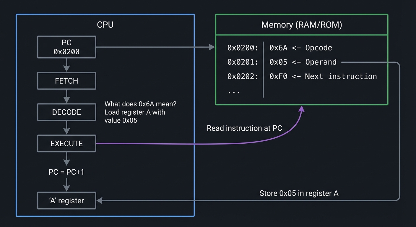
At the heart of every CPU—and every emulator—is the fetch-decode-execute cycle. This is the fundamental loop that turns bytes in memory into running programs.
How CPUs Work: A Mental Model
Think of a CPU as a clerk in an office with three tasks:
- Fetch: The clerk looks at a to-do list (program counter) to find the next instruction.
- Decode: The clerk reads the instruction and figures out what it means.
- Execute: The clerk performs the action and updates the to-do list to point to the next instruction.
This repeats millions of times per second, creating the illusion of a “running program.”
The Cycle in Detail
┌─────────────────────────────────────────────────────────────────┐
│                    FETCH-DECODE-EXECUTE CYCLE                    │
└─────────────────────────────────────────────────────────────────┘

   ┌──────────┐
   │   CPU    │
   │          │
   │  ┌────┐  │       ┌─────────────────────────────────────┐
   │  │ PC │──┼──────>│  Memory (RAM/ROM)                   │
   │  └────┘  │       │                                     │
   │    │     │       │  0x0200: 0x6A  <- Opcode           │
   │    v     │       │  0x0201: 0x05  <- Operand          │
   │ FETCH    │       │  0x0202: 0xF0  <- Next instruction │
   │    │     │       │  ...                                │
   │    v     │       └─────────────────────────────────────┘
   │ DECODE   │              ^
   │    │     │              │
   │    v     │              │ Read instruction at PC
   │ EXECUTE  │──────────────┘
   │    │     │
   │    v     │       What does 0x6A mean?
   │ PC = PC+1│       "Load register A with value 0x05"
   │          │
   │  ┌────┐  │
   │  │ A  │<─┼───── Store 0x05 in register A
   │  └────┘  │
   └──────────┘
Example: CHIP-8 Instruction Execution
Let’s trace one instruction through the cycle:
Memory at 0x200:
0x200: 0x6A 0x05 (Instruction: "LD V[A], 0x05" - Load register V[10] with value 5)
Fetch:
uint16_t opcode = (memory[PC] << 8) | memory[PC + 1];  // opcode = 0x6A05
PC += 2;  // Move program counter to next instruction
Decode:
uint8_t instruction_type = (opcode & 0xF000) >> 12;  // 0x6 = "LD Vx, byte"
uint8_t x = (opcode & 0x0F00) >> 8;                  // 0xA = register index
uint8_t value = opcode & 0x00FF;                     // 0x05 = value to load
Execute:
V[x] = value; // V[10] = 5
Why This Matters for Emulation
When you build an emulator, you are implementing this cycle in software. Your emulator’s main loop looks like this:
while (running) {
    uint16_t opcode = fetch(cpu);        // Read from emulated memory
    Instruction instr = decode(opcode);  // Figure out what it means
    execute(cpu, instr);                 // Perform the operation
    update_timers(cpu);                  // Advance system state
    if (should_render_frame(cpu)) {
        render_screen();                 // Draw to screen
    }
}
Every emulator—from CHIP-8 to PlayStation—follows this pattern. The complexity varies (Game Boy has 500+ opcodes, PS1 has coprocessors), but the fundamental structure is the same.
Memory Architecture in Emulation
Memory is not just “a big array.” In retro systems, memory was carefully partitioned, often with special-purpose regions and hardware tricks to overcome addressing limitations.
Memory Maps: Where Everything Lives
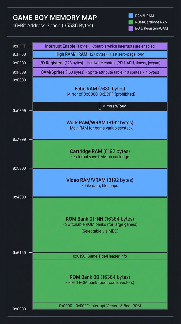
A memory map describes what lives at each address range. Here’s the Game Boy’s memory map:
┌─────────────────────────────────────────────────────────────────┐
│                    GAME BOY MEMORY MAP                           │
└─────────────────────────────────────────────────────────────────┘

0xFFFF ┌──────────────────┐
       │  Interrupt Enable│  (1 byte) - Controls which interrupts are enabled
       ├──────────────────┤
0xFF80 │  High RAM (HRAM) │  (127 bytes) - Fast zero-page RAM
       ├──────────────────┤
0xFF00 │  I/O Registers   │  (128 bytes) - Hardware control (PPU, APU, timers, joypad)
       ├──────────────────┤
0xFE00 │  OAM (Sprites)   │  (160 bytes) - Sprite attribute table (40 sprites × 4 bytes)
       ├──────────────────┤
0xE000 │  Echo RAM        │  (7680 bytes) - Mirror of 0xC000-0xDDFF (prohibited)
       ├──────────────────┤
0xC000 │  Work RAM (WRAM) │  (8192 bytes) - Main RAM for game variables/stack
       ├──────────────────┤
0xA000 │  Cartridge RAM   │  (8192 bytes) - External save RAM on cartridge
       ├──────────────────┤
0x8000 │  Video RAM (VRAM)│  (8192 bytes) - Tile data, tile maps
       ├──────────────────┤
0x4000 │  ROM Bank 01-NN  │  (16384 bytes) - Switchable ROM banks (for large games)
       ├──────────────────┤
0x0000 │  ROM Bank 00     │  (16384 bytes) - Fixed ROM bank (boot code, vectors)
       └──────────────────┘

When the CPU reads from 0xFF00, it's not reading RAM—it's reading
the joypad register. When it writes to 0x8000, it's modifying tile
graphics, not general memory. This is called MEMORY-MAPPED I/O.
Memory-Mapped I/O
In retro systems, hardware registers appear as memory addresses. Writing to these addresses controls hardware:
// Reading joypad state on Game Boy
uint8_t joypad_state = memory[0xFF00];  // This reads a hardware register!

// Writing to PPU control register
memory[0xFF40] = 0x91;  // Enable LCD, background, sprites - controls hardware!

// Loading a tile into VRAM
memory[0x8000] = 0xFF;  // This writes to video memory, changing graphics
This is why emulators implement memory as functions, not arrays:
uint8_t read_byte(uint16_t address) {
    if (address < 0x8000) {
        return rom[address];           // Reading ROM
    } else if (address >= 0xFF00 && address <= 0xFF7F) {
        return read_io_register(address);  // Reading hardware
    } else if (address >= 0x8000 && address < 0xA000) {
        return vram[address - 0x8000]; // Reading video RAM
    }
    // ... and so on for every memory region
}
Bank Switching: Overcoming Address Space Limits
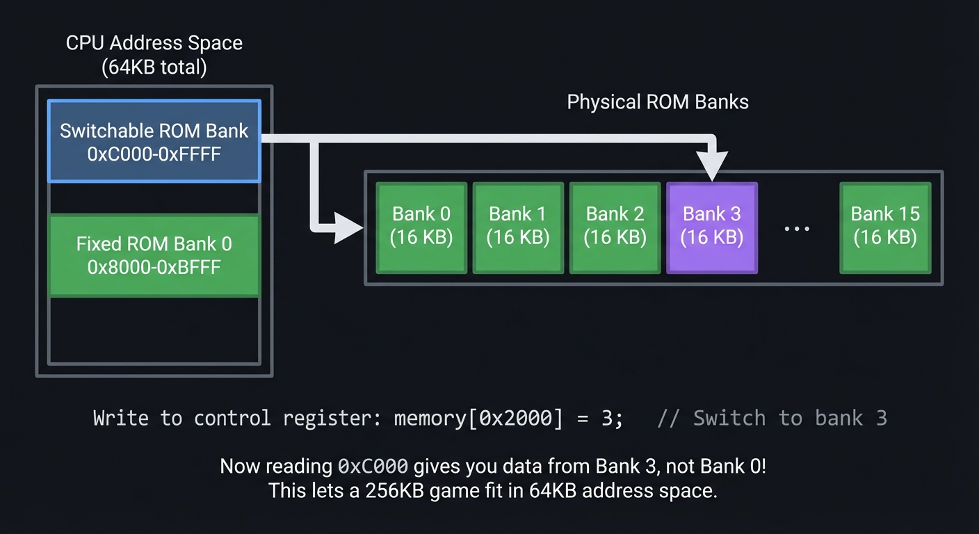
Early CPUs had limited addressing (8-bit or 16-bit), meaning they could only address 64KB. But games grew larger than 64KB. The solution? Bank switching—hardware that swaps which ROM/RAM is visible at a given address.
┌─────────────────────────────────────────────────────────────────┐
│                    BANK SWITCHING EXAMPLE                        │
│                   (NES Mapper / GB MBC Cartridge)                │
└─────────────────────────────────────────────────────────────────┘

CPU Address Space (64KB total):

  ┌─────────────────┐
  │  0xC000-0xFFFF  │ ──┐
  │  Switchable     │   │  ┌──────────────────────────────────┐
  │  ROM Bank       │   └─>│  Bank 0  │  Bank 1  │  Bank 2  │ ... │  Bank 15 │
  ├─────────────────┤      │  16 KB   │  16 KB   │  16 KB   │     │  16 KB   │
  │  0x8000-0xBFFF  │      └──────────────────────────────────┘
  │  Fixed          │         ^
  │  ROM Bank 0     │         │
  └─────────────────┘         │
                              │
                Write to control register:
                memory[0x2000] = 3;  // Switch to bank 3

Now reading 0xC000 gives you data from Bank 3, not Bank 0!
This lets a 256KB game fit in 64KB address space.
Your emulator must track which bank is active:
uint8_t current_rom_bank = 1;  // Track active bank

void write_byte(uint16_t address, uint8_t value) {
    if (address >= 0x2000 && address < 0x4000) {
        // Writing to bank controller
        current_rom_bank = value & 0x1F;  // Switch banks
    }
}

uint8_t read_byte(uint16_t address) {
    if (address >= 0x4000 && address < 0x8000) {
        // Reading from switchable bank
        uint32_t rom_address = (current_rom_bank * 0x4000) + (address - 0x4000);
        return rom[rom_address];
    }
}
Bus Architecture: Shared Highway
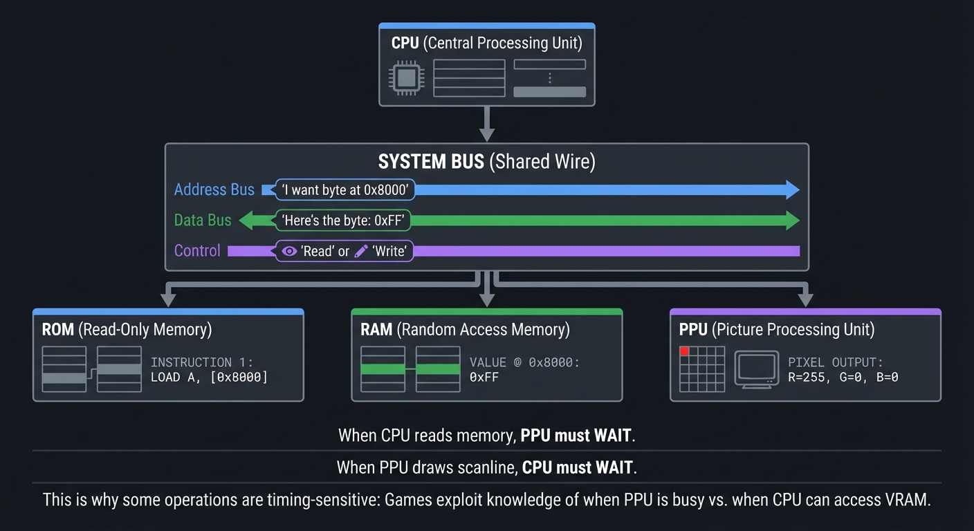
The bus is the shared pathway connecting CPU, memory, and peripherals. Only one component can use it at a time.
┌─────────────────────────────────────────────────────────────────┐
│                         BUS ARCHITECTURE                         │
└─────────────────────────────────────────────────────────────────┘

        ┌─────────┐
        │   CPU   │
        └────┬────┘
             │
             v
    ┌────────────────┐  (Address Bus: "I want byte at 0x8000")
    │   SYSTEM BUS   │  (Data Bus: "Here's the byte: 0xFF")
    │  (Shared Wire) │  (Control: "Read" or "Write")
    └────────────────┘
         │     │     │
         v     v     v
      ┌───┐ ┌───┐ ┌────┐
      │ROM│ │RAM│ │PPU │
      └───┘ └───┘ └────┘

When CPU reads memory, PPU must WAIT.
When PPU draws scanline, CPU must WAIT.

This is why some operations are timing-sensitive:
Games exploit knowledge of when PPU is busy vs. when CPU can access VRAM.
Graphics/PPU Fundamentals
Retro graphics weren’t drawn pixel-by-pixel. They used tile-based rendering—a memory-efficient system that made games possible on limited hardware.
Tile-Based Graphics: Building Blocks
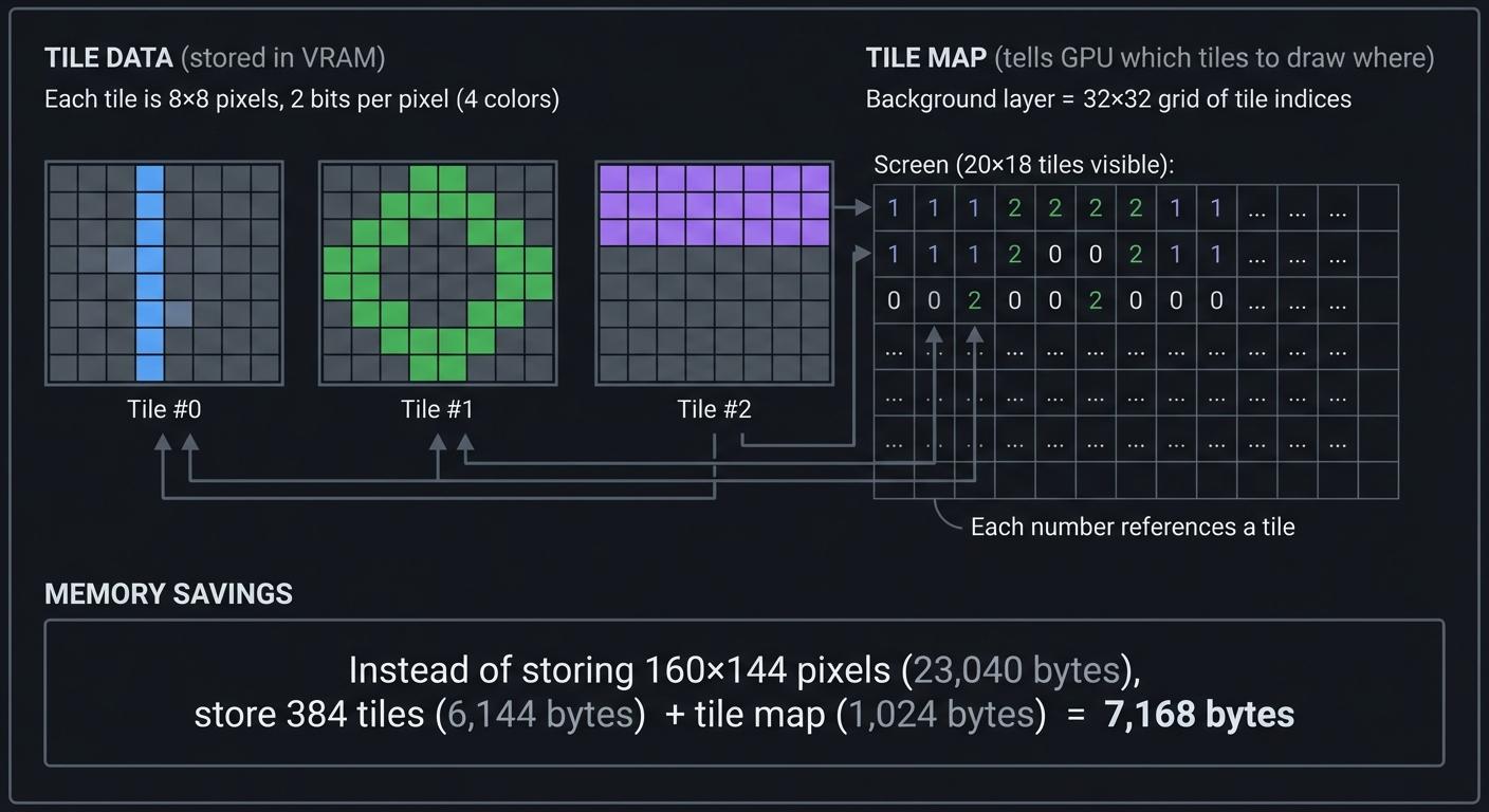
Instead of storing every pixel, games stored 8×8 tiles and assembled them into screens.
┌─────────────────────────────────────────────────────────────────┐
│                    TILE-BASED RENDERING                          │
└─────────────────────────────────────────────────────────────────┘

TILE DATA (stored in VRAM):
Each tile is 8×8 pixels, 2 bits per pixel (4 colors)

Tile #0:        Tile #1:        Tile #2:
┌────────┐      ┌────────┐      ┌────────┐
│........│      │..████..│      │████████│
│..██....│      │.██..██.│      │██....██│
│..██....│      │██....██│      │██....██│
│..██....│      │██....██│      │██....██│
│..██....│      │.██..██.│      │████████│
│..██....│      │..████..│      │........│
│..██....│      │........│      │........│
│........│      │........│      │........│
└────────┘      └────────┘      └────────┘

TILE MAP (tells GPU which tiles to draw where):
Background layer = 32×32 grid of tile indices

Screen (20×18 tiles visible):
┌─────────────────────────────┐
│  1  1  2  2  2  2  1  1 ... │  <- Each number references a tile
│  1  1  2  0  0  2  1  1 ... │
│  0  0  2  0  0  2  0  0 ... │
│  ... ... ... ... ... ...   │
└─────────────────────────────┘

Instead of storing 160×144 pixels (23,040 bytes),
store 384 tiles (6,144 bytes) + tile map (1,024 bytes) = 7,168 bytes
Your emulator must render tiles to a framebuffer:
void render_scanline(int line) {
    for (int x = 0; x < 160; x++) {
        // Which tile are we in?
        int tile_x = (x + scroll_x) / 8;
        int tile_y = (line + scroll_y) / 8;

        // Which pixel within the tile?
        int pixel_x = (x + scroll_x) % 8;
        int pixel_y = (line + scroll_y) % 8;

        // Look up tile index from tile map
        uint8_t tile_index = tile_map[tile_y * 32 + tile_x];

        // Get pixel color from tile data
        uint8_t color = get_tile_pixel(tile_index, pixel_x, pixel_y);

        // Draw to framebuffer
        framebuffer[line * 160 + x] = palette[color];
    }
}
Scanline Rendering: Drawing Line by Line
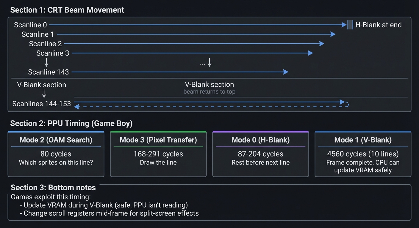
Old CRT TVs drew the screen line-by-line using an electron beam. Emulators simulate this:
┌─────────────────────────────────────────────────────────────────┐
│                       SCANLINE RENDERING                         │
└─────────────────────────────────────────────────────────────────┘

CRT Beam Movement:
┌─────────────────────────────────────────┐
│ >─────────────────────────────────────> │ Scanline 0 (H-Blank at end)
│   >───────────────────────────────────> │ Scanline 1
│     >─────────────────────────────────> │ Scanline 2
│       >───────────────────────────────> │ Scanline 3
│         ...                             │
│                                         │
│ >─────────────────────────────────────> │ Scanline 143
├─────────────────────────────────────────┤
│         (V-Blank - beam returns to top) │ Scanlines 144-153
└─────────────────────────────────────────┘

PPU Timing (Game Boy):
- Mode 2 (OAM Search):  80 cycles  - "Which sprites on this line?"
- Mode 3 (Pixel Transfer): 168-291 cycles - "Draw the line"
- Mode 0 (H-Blank):     87-204 cycles - "Rest before next line"
- Mode 1 (V-Blank):     4560 cycles (10 lines) - "Frame complete, CPU can update VRAM safely"

Games exploit this timing:
- Update VRAM during V-Blank (safe, PPU isn't reading)
- Change scroll registers mid-frame for split-screen effects
Sprites vs Background
Two layers: background (scrolling world) and sprites (moving objects).
┌─────────────────────────────────────────────────────────────────┐
│                     SPRITES VS BACKGROUND                        │
└─────────────────────────────────────────────────────────────────┘

Background Layer (32×32 tiles, scrolls):
┌──────────────────────────────────┐
│ ░░░░░░░░░░░░░░░░░░░░░░░░░░░░░░░ │
│ ░░░░  Level 1-1 Ground  ░░░░░░░ │  <- Stored in tile map
│ ░░░░░░░░░░░░░░░░░░░░░░░░░░░░░░░ │
│ ██████████████████████████████  │
└──────────────────────────────────┘

Sprite Layer (40 sprites, 8×8 or 8×16 each):
┌──────────────────────────────────┐
│                 ┌──┐             │
│                 │🍄│   (Sprite 0)│  <- Stored in OAM
│           ┌──┐  └──┘             │     (Object Attribute Memory)
│           │👤│       (Sprite 1)  │
│           └──┘                   │
└──────────────────────────────────┘

Combined (as displayed):
┌──────────────────────────────────┐
│ ░░░░░░░░░░░░  ┌──┐  ░░░░░░░░░░░ │
│ ░░░░░░░░░░░░  │🍄│  ░░░░░░░░░░░ │  Sprite over background
│ ░░░░░░░┌──┐░░ └──┘ ░░░░░░░░░░░░ │
│ ███████│👤│████████████████████  │  Sprite over ground
│        └──┘                      │
└──────────────────────────────────┘

Priority Rules:
- Sprite pixel = transparent (color 0) → Show background
- Sprite priority flag = 0 → Sprite always on top
- Sprite priority flag = 1 → Sprite behind background color 1-3
![]()
Audio/APU Fundamentals
Retro audio was synthesized in real-time using simple waveform generators.
Sound Channels: Building Music from Waves
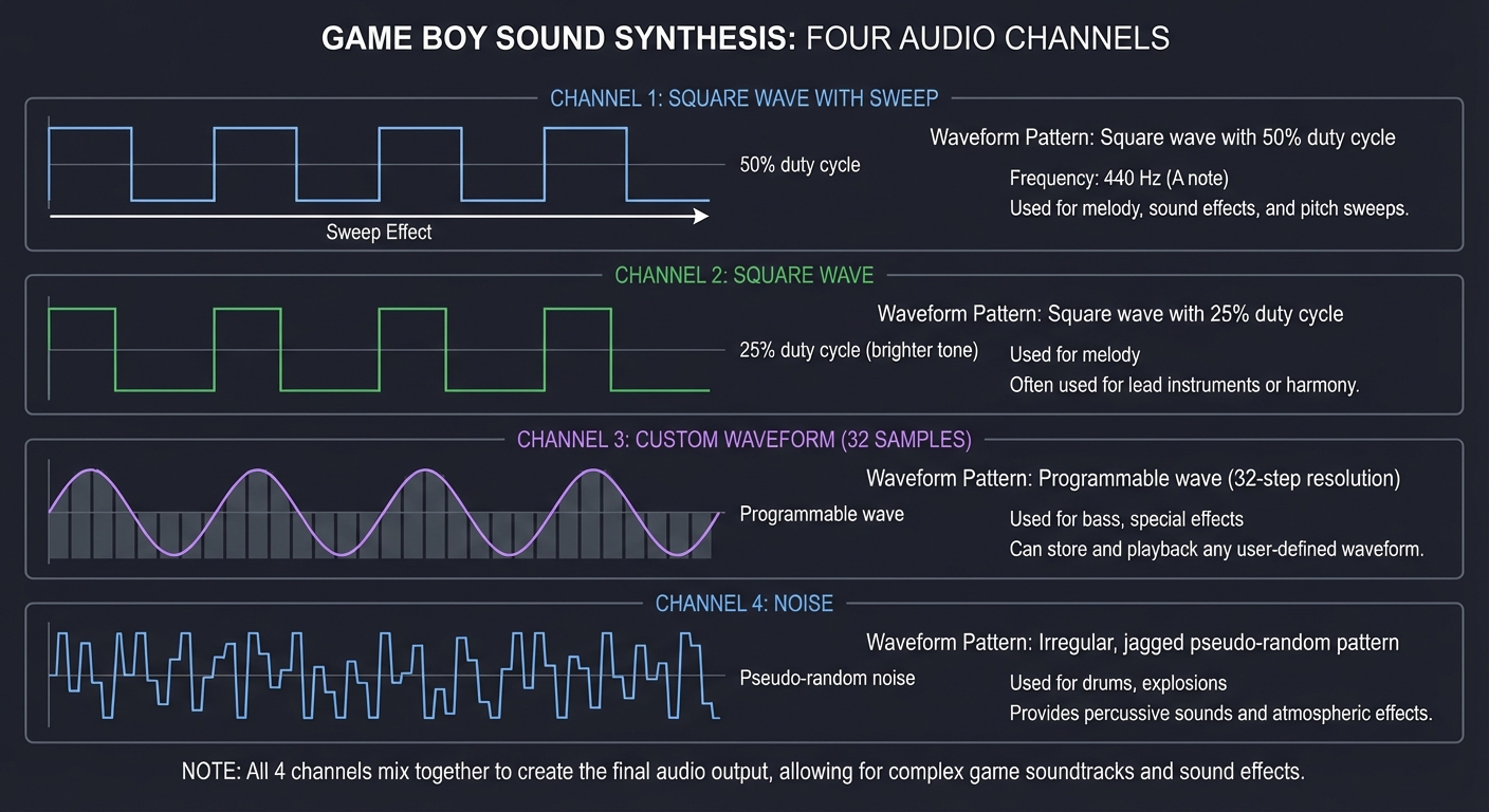
Game Boy has 4 channels, each generating different waveforms:
┌─────────────────────────────────────────────────────────────────┐
│                        AUDIO CHANNELS                            │
└─────────────────────────────────────────────────────────────────┘

Channel 1: Square Wave with Sweep
  ____    ____    ____         ← 50% duty cycle
 |    |  |    |  |    |
_|    |__|    |__|    |__      Frequency: 440 Hz (A note)

Channel 2: Square Wave
  __  __  __  __  __           ← 25% duty cycle (brighter tone)
 |  ||  ||  ||  ||  |
_|  ||  ||  ||  ||  |____      Used for melody

Channel 3: Custom Waveform (32 samples)
   /\    /\    /\             ← Programmable wave
  /  \  /  \  /   /    \/    \/    \           Used for bass, special effects

Channel 4: Noise
 |___|‾|____|‾‾|__|‾|_|‾|     ← Pseudo-random noise
                               Used for drums, explosions

All 4 channels mix together to create the final audio output.
Your emulator generates these waveforms:
// Square wave generation (Channel 1)
int16_t generate_square_wave(Channel *ch) {
    // Frequency determines how fast wave oscillates
    ch->phase += ch->frequency / SAMPLE_RATE;
    if (ch->phase >= 1.0) ch->phase -= 1.0;

    // Duty cycle determines wave shape
    float threshold = duty_cycles[ch->duty];  // 0.125, 0.25, 0.5, 0.75
    int16_t amplitude = ch->volume * 512;

    return (ch->phase < threshold) ? amplitude : -amplitude;
}

// Mix all channels
int16_t mix_audio() {
    int16_t sample = 0;
    sample += generate_square_wave(&channel1);
    sample += generate_square_wave(&channel2);
    sample += generate_wave(&channel3);
    sample += generate_noise(&channel4);
    return sample / 4;  // Average the channels
}
Envelopes: Shaping Sound Over Time
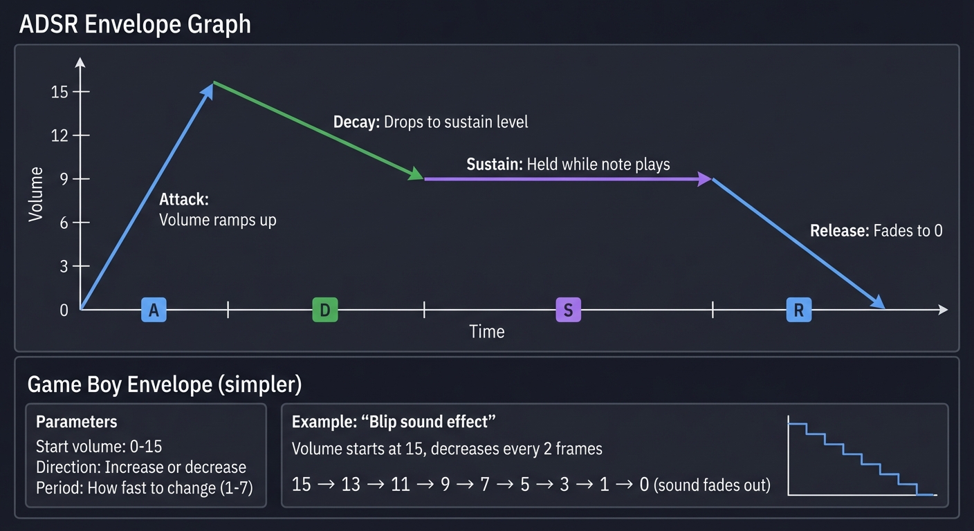
Envelopes control how volume changes over time (think of how a piano note fades):
┌─────────────────────────────────────────────────────────────────┐
│                    VOLUME ENVELOPE (ADSR)                        │
└─────────────────────────────────────────────────────────────────┘

Volume
  ^
15│    /  │   /  \___________         Attack: Volume ramps up
  │  /              \         Decay: Drops to sustain level
  │ /                \        Sustain: Held while note plays
  │/                  \__     Release: Fades to 0
 0└────────────────────────> Time
   A D  Sustain      R

Game Boy Envelope (simpler):
- Start volume: 0-15
- Direction: Increase or decrease
- Period: How fast to change (1-7)

Example: "Blip" sound effect
  Volume starts at 15, decreases every 2 frames
  15 → 13 → 11 → 9 → 7 → 5 → 3 → 1 → 0 (sound fades out)
Timing & Synchronization
Accurate emulation requires running components in sync at precise clock speeds.
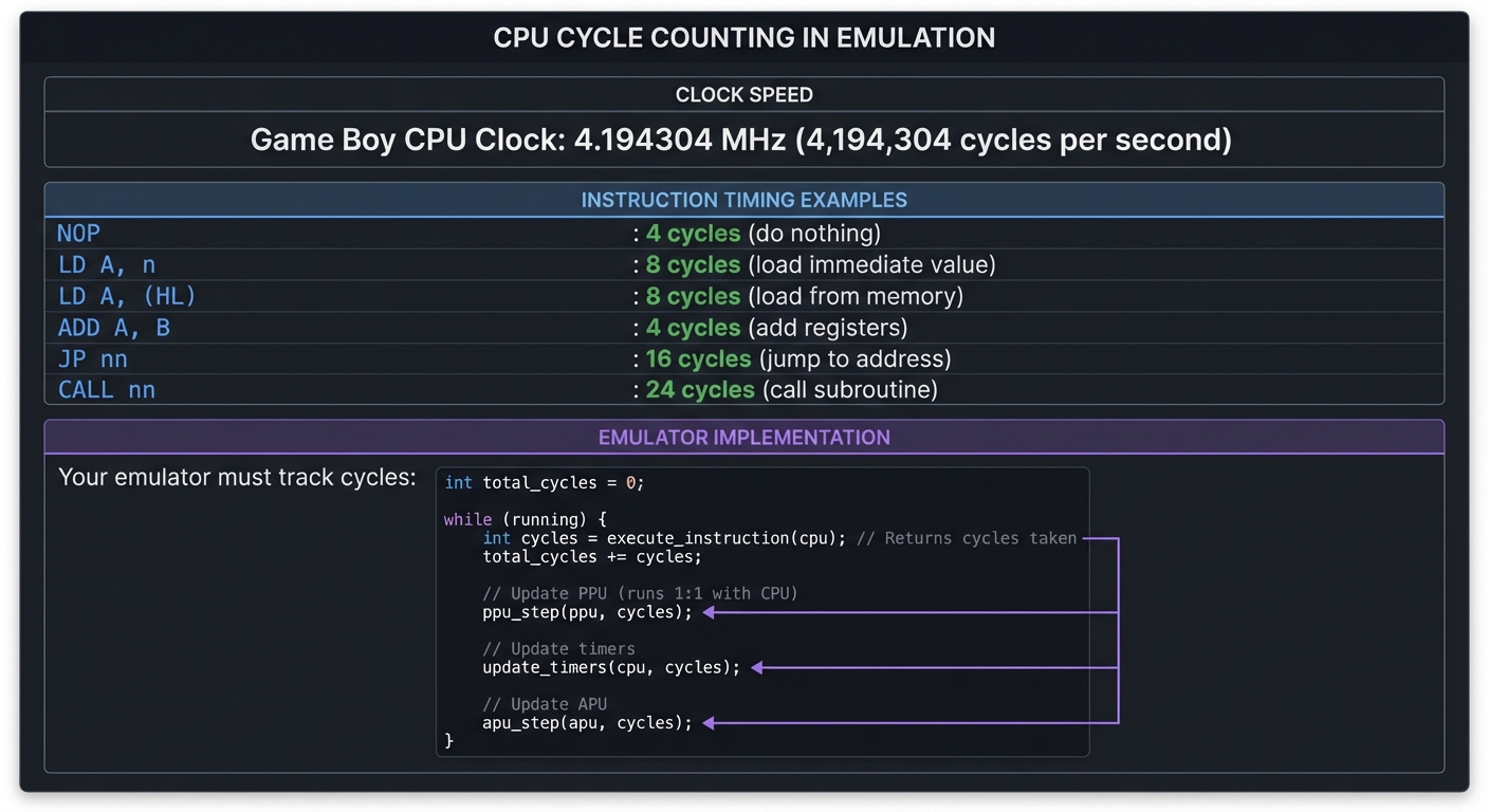
Cycle Counting: The Emulator’s Heartbeat
CPUs don’t execute instructions instantly—each takes a specific number of clock cycles.
┌─────────────────────────────────────────────────────────────────┐
│                         CYCLE COUNTING                           │
└─────────────────────────────────────────────────────────────────┘

Game Boy CPU Clock: 4.194304 MHz (4,194,304 cycles per second)

Instruction timing examples:
  NOP            : 4 cycles   (do nothing)
  LD A, n        : 8 cycles   (load immediate value)
  LD A, (HL)     : 8 cycles   (load from memory)
  ADD A, B       : 4 cycles   (add registers)
  JP nn          : 16 cycles  (jump to address)
  CALL nn        : 24 cycles  (call subroutine)

Your emulator must track cycles:

int total_cycles = 0;

while (running) {
    int cycles = execute_instruction(cpu);  // Returns cycles taken
    total_cycles += cycles;

    // Update PPU (runs 1:1 with CPU)
    ppu_step(ppu, cycles);

    // Update timers
    update_timers(cpu, cycles);

    // Update APU
    apu_step(apu, cycles);
}
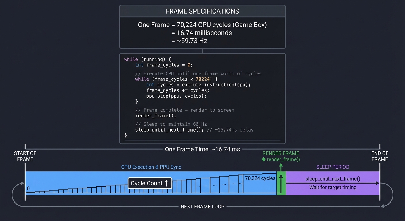
Frame Timing: 60 Hz Synchronization
Retro consoles rendered at 59.73 Hz (NTSC) or 50 Hz (PAL). Your emulator must match this:
┌─────────────────────────────────────────────────────────────────┐
│                        FRAME TIMING                              │
└─────────────────────────────────────────────────────────────────┘

One Frame = 70,224 CPU cycles (Game Boy)
          = 16.74 milliseconds
          = ~59.73 Hz

Emulator loop:

while (running) {
    int frame_cycles = 0;

    // Execute CPU until one frame worth of cycles
    while (frame_cycles < 70224) {
        int cycles = execute_instruction(cpu);
        frame_cycles += cycles;
        ppu_step(ppu, cycles);  // PPU keeps pace
    }

    // Frame complete - render to screen
    render_frame();

    // Sleep to maintain 60 Hz
    sleep_until_next_frame();  // ~16.74ms delay
}
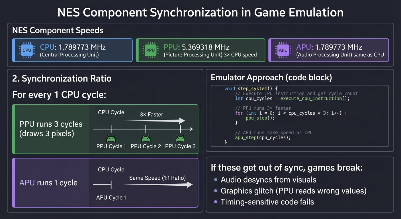
Component Synchronization
CPU, PPU, and APU run at different speeds but must stay synchronized:
┌─────────────────────────────────────────────────────────────────┐
│                   COMPONENT SYNCHRONIZATION                      │
└─────────────────────────────────────────────────────────────────┘

NES Example:
  CPU: 1.789773 MHz
  PPU: 5.369318 MHz (3× CPU speed)
  APU: 1.789773 MHz (same as CPU)

For every 1 CPU cycle:
  - PPU runs 3 cycles (draws 3 pixels)
  - APU runs 1 cycle

Emulator approach:

void step_system() {
    int cpu_cycles = execute_cpu_instruction();

    // PPU runs 3× faster
    for (int i = 0; i < cpu_cycles * 3; i++) {
        ppu_step();
    }

    // APU runs same speed as CPU
    apu_step(cpu_cycles);
}

If these get out of sync, games break:
- Audio desyncs from visuals
- Graphics glitch (PPU reads wrong values)
- Timing-sensitive code fails
Concept Summary Table
This table maps high-level concepts to what you need to internalize for building emulators:
| Concept Cluster | What You Need to Internalize | Why It Matters |
|---|---|---|
| Fetch-Decode-Execute | How instructions are read, parsed, and executed in sequence | This is the CPU’s fundamental loop—every emulator implements this |
| Opcode Decoding | Extracting instruction type and operands from binary | You’ll decode 35 opcodes (CHIP-8) to 500+ opcodes (Game Boy) to thousands (PlayStation) |
| Registers & Flags | CPU internal state: program counter, stack pointer, status flags | All CPU operations manipulate this state; bugs here break everything |
| Memory Maps | Different address ranges map to ROM, RAM, I/O, graphics | Reading 0xFF00 vs 0xC000 does completely different things |
| Memory-Mapped I/O | Hardware registers appear as memory addresses | Writing to 0x8000 changes graphics; reading 0xFF00 reads controller input |
| Bank Switching | Swapping which ROM/RAM is visible at an address | Games larger than 64KB require this; your emulator must track active banks |
| Tile-Based Graphics | Screens built from 8×8 reusable tiles, not individual pixels | Memory-efficient; you’ll implement tile lookup and rendering |
| Scanline Rendering | Drawing the screen line-by-line, matching CRT timing | Games exploit scanline timing for effects; you’ll implement PPU state machines |
| Sprites vs Background | Two layers with priority rules | Games need moving objects (sprites) over scrolling worlds (background) |
| Sound Synthesis | Generating waveforms (square, triangle, noise) mathematically | You’ll implement oscillators, mix channels, and output to speakers |
| Envelopes | Volume changes over time (attack, decay, sustain, release) | Makes sounds musical instead of harsh beeps |
| Cycle Counting | Tracking how many clock cycles elapsed | Games rely on precise timing; off by 1 cycle can break games |
| Frame Timing | Synchronizing to 50/60 Hz refresh rate | Keeps emulator running at correct speed, not too fast or slow |
| Component Sync | CPU, PPU, APU must stay in lockstep | Async components cause audio/video desync and glitches |
| Interrupts | Hardware signals that pause CPU to handle events | V-Blank interrupt signals frame complete; button press triggers interrupt |
| Test-Driven Development | Using test ROMs to verify accuracy | Test ROMs catch subtle bugs; essential for accurate emulation |
Deep Dive Reading By Concept
This table maps each concept to specific book chapters and online resources:
| Concept | Resource | Chapter/Section | Why Read This |
|---|---|---|---|
| Fetch-Decode-Execute | Code: The Hidden Language by Charles Petzold | Chapters 17-18 | Best intuitive explanation of how CPUs work |
| CPU Architecture | Computer Systems: A Programmer’s Perspective by Bryant & O’Hallaron | Chapter 4 | Y86 processor design teaches CPU internals |
| Opcode Decoding | The Secret Life of Programs by Jonathan Steinhart | Chapter 8 | Practical instruction set design |
| Memory Management | Computer Systems: A Programmer’s Perspective by Bryant & O’Hallaron | Chapter 6 | Memory hierarchy, caching, addressing |
| Memory-Mapped I/O | The Secret Life of Programs by Jonathan Steinhart | Chapter 10 | How hardware appears as memory |
| Bitwise Operations | C Programming: A Modern Approach by K.N. King | Chapter 20 | Mastering bit manipulation for opcode decoding |
| Graphics Fundamentals | Computer Graphics from Scratch by Gabriel Gambetta | Chapters 1-3, 11 | Pixel rendering, rasterization, tile systems |
| Tile-Based Rendering | Pan Docs - Rendering | Full page | Definitive Game Boy graphics reference |
| Scanline Rendering | Game Boy Coding Adventure by Maximilien Dagois | Chapter 5 | Practical PPU state machine implementation |
| Sprites & OAM | Pan Docs - OAM | Full page | Sprite attribute memory format and priority |
| Sound Synthesis | Designing Sound by Andy Farnell | Chapters 5-8 | Pure Data sound synthesis from scratch |
| APU Architecture | Pan Docs - Audio | Full page | Game Boy sound hardware specification |
| Digital Audio | Computer Music by Charles Dodge & Thomas Jerse | Chapter 3 | Sample rates, digital waveforms, synthesis |
| Timing & Synchronization | Computer Organization and Design by Patterson & Hennessy | Chapter 5 | Processor timing, pipelining, interrupts |
| Cycle-Accurate Emulation | Emulation Accuracy by endrift | Full article | Why cycle accuracy matters, how to achieve it |
| Interrupts | Computer Organization and Design by Patterson & Hennessy | Chapter 5.6 | Interrupt handling, priorities, vectors |
| 6502 Architecture | NESDev Wiki - CPU | Full page | 6502 opcodes, addressing modes, quirks |
| Z80/LR35902 | Pan Docs - CPU | Full page | Game Boy CPU instruction set reference |
| ARM Architecture | ARM System Developer’s Guide by Andrew Sloss | Chapters 2-4 | ARM7TDMI for Game Boy Advance |
| MIPS Architecture | See MIPS Run by Dominic Sweetman | Chapters 1-5 | MIPS R3000 for PlayStation |
| Test-Driven Development | Test Driven Development by Kent Beck | Chapters 1-5 | Writing test ROMs, verification methodology |
| Binary Analysis | Practical Binary Analysis by Dennis Andriesse | Chapters 2, 6 | Disassembly, reverse engineering, debugging |
| JIT Compilation | Engineering a Compiler by Cooper & Torczon | Chapters 4, 13 | Code generation, register allocation |
| Digital Logic (FPGA) | Digital Design and Computer Architecture by Harris & Harris | Chapters 1-5 | Building CPUs in hardware |
| Verilog (FPGA) | Verilog HDL by Samir Palnitkar | Chapters 2-7 | Hardware description language for FPGAs |
Project Recommendations
The following projects are ordered by difficulty and complexity. Each builds upon concepts learned in previous projects.
Project 1: CHIP-8 Interpreter
- File: RETRO_GAME_EMULATION_PROJECTS.md
- Main Programming Language: C
- Alternative Programming Languages: Rust, Python, Go
- Coolness Level: Level 3: Genuinely Clever
- Business Potential: 1. The “Resume Gold” (Educational/Personal Brand)
- Difficulty: Level 1: Beginner (The Tinkerer)
- Knowledge Area: CPU Emulation / Virtual Machines
- Software or Tool: CHIP-8 Virtual Machine
- Main Book: “Computer Systems: A Programmer’s Perspective” by Bryant & O’Hallaron
What you’ll build: A complete interpreter for the CHIP-8 virtual machine that can run classic games like Pong, Space Invaders, and Tetris clones.
Why it teaches emulation: CHIP-8 is the “Hello World” of emulator development. It has only 35 opcodes, simple graphics (64x32 monochrome), and no complex timing requirements. You’ll learn the fundamental fetch-decode-execute loop that every emulator uses, without getting lost in hardware complexity.
Core challenges you’ll face:
- Opcode decoding (parsing 2-byte instructions, extracting operands) → maps to instruction set understanding
- Register management (16 general-purpose registers, I register, timers) → maps to CPU state modeling
- Stack implementation (for subroutine calls/returns) → maps to control flow
- Display rendering (XOR-based sprite drawing) → maps to graphics fundamentals
- Keyboard input mapping (hex keypad to modern keyboard) → maps to I/O handling
Key Concepts:
- Fetch-Decode-Execute: “Code: The Hidden Language” Chapter 17-18 - Charles Petzold
- Bitwise Operations: “C Programming: A Modern Approach” Chapter 20 - K.N. King
- Memory-Mapped I/O: “Computer Systems: A Programmer’s Perspective” Chapter 6 - Bryant & O’Hallaron
- Stack Machines: “The Secret Life of Programs” Chapter 8 - Jonathan Steinhart
Difficulty: Beginner Time estimate: Weekend to 1 week Prerequisites: Basic C/Rust/Python, understanding of binary/hex
Real world outcome:
- Run classic CHIP-8 ROMs: Pong, Breakout, Space Invaders, Tetris clones
- See pixels appearing on screen as your emulator executes instructions
- Play the games with your keyboard mapped to the hex keypad
$ ./chip8 roms/PONG
[CHIP-8] Loading ROM: PONG (246 bytes)
[CHIP-8] Starting execution...
# A playable Pong game appears in your window!
Learning milestones:
- ROM loads and opcodes print → You understand instruction fetching
- Simple opcodes execute (jumps, register loads) → You’ve built a working CPU core
- Graphics appear on screen → You understand display/sprite rendering
- Games are fully playable → You’ve internalized the emulation loop
Resources:
- CHIP-8 Guide by Tobias V. Langhoff - Excellent high-level walkthrough
- Austin Morlan’s CHIP-8 in C++ - Detailed implementation guide
The Core Question You’re Answering
“How does a processor fetch, decode, and execute instructions in a continuous loop?”
Concepts You Must Understand First
- Binary Representation & Hexadecimal
- Can you convert 0x6A02 to binary and explain what each bit might represent?
- Why do we use hexadecimal instead of binary when reading opcodes?
- How many bits are in a CHIP-8 instruction?
- Book: “C Programming: A Modern Approach” Chapter 20 - K.N. King
- Bitwise Operations (AND, OR, XOR, Shifts)
- How would you extract the second nibble from 0x6A02?
- Why does CHIP-8 use XOR for drawing pixels instead of just setting them?
- What’s the difference between » (right shift) and & (bitwise AND) for extracting bits?
- Book: “C Programming: A Modern Approach” Chapter 20 - K.N. King
- Memory as an Array of Bytes
- If memory starts at address 0x200, where is the byte at index 0?
- How do you read a 2-byte instruction from memory at address PC?
- What’s the difference between memory[PC] and *(memory + PC)?
- Book: “Computer Systems: A Programmer’s Perspective” Chapter 3 - Bryant & O’Hallaron
- The Stack (LIFO Structure)
- When you call a subroutine, what must you save?
- Why does the stack pointer increment when you push and decrement when you pop?
- What happens if you return when the stack is empty?
- Book: “The Secret Life of Programs” Chapter 8 - Jonathan Steinhart
- Program Counter (PC)
- Why does PC automatically advance by 2 after fetching an instruction?
- How does a jump instruction differ from incrementing PC?
- What happens to PC during a subroutine call?
- Book: “Code: The Hidden Language” Chapter 17-18 - Charles Petzold
Questions to Guide Your Design
- Should you decode all 35 opcodes with a giant switch statement, or use a lookup table?
- How will you handle the two-byte instruction format - read byte-by-byte or combine them first?
- Should timers decrement in the main loop or on a separate thread/timer?
- How do you map the CHIP-8 hex keypad (0-F) to a modern QWERTY keyboard?
- Should you render pixels immediately when DRW executes, or buffer them for the next frame?
Thinking Exercise
Trace through this CHIP-8 code by hand. What appears on screen?
Address | Opcode | Instruction
--------|--------|------------
0x200   | 6A 05  | LD VA, 5      (Set V[A] = 5)
0x202   | 6B 02  | LD VB, 2      (Set V[B] = 2)
0x204   | A2 10  | LD I, 0x210   (Set I = 0x210)
0x206   | DA B5  | DRW VA, VB, 5 (Draw 5-byte sprite at (V[A], V[B]))
0x208   | 12 08  | JP 0x208      (Infinite loop)

Memory at 0x210:
0xF0 (11110000)
0x90 (10010000)
0x90 (10010000)
0x90 (10010000)
0xF0 (11110000)
Questions:
- Where on the 64x32 screen will the sprite appear?
- What does the sprite look like? (Hint: Draw it out on graph paper)
- Why is there a jump at the end?
- What happens if the sprite overlaps with something already drawn?
The Interview Questions They’ll Ask
- “Walk me through what happens when your emulator executes one frame. Start from reading the ROM.”
- “The instruction 0x8XY4 adds VY to VX and sets VF to 1 if there’s a carry. How do you detect carry in C?”
- “CHIP-8 instructions are 2 bytes but memory is byte-addressable. How do you fetch instructions?”
- “Explain how the XOR-based drawing works. Why does drawing the same sprite twice erase it?”
- “Your emulator runs too fast on modern hardware. How do you throttle it to ~60 FPS?”
- “How would you debug a ROM that displays garbage on screen? What would you check first?”
Hints in Layers
Hint 1: Decoding Instructions The opcode 0x6A02 means “Set register A to 0x02”. Notice the pattern:
- First nibble (6) = instruction type
- Second nibble (A) = which register
- Last two nibbles (02) = the value
uint16_t opcode = 0x6A02;
uint8_t instr = (opcode & 0xF000) >> 12;  // 6
uint8_t x     = (opcode & 0x0F00) >> 8;   // A
uint8_t nn    = (opcode & 0x00FF);        // 02
Hint 2: The Fetch-Decode-Execute Loop Your main emulation loop should look like:
while (running) {
    uint16_t opcode = fetch(PC);
    PC += 2;
    decode_and_execute(opcode);
    update_timers();
    if (draw_flag) render();
}
Hint 3: Drawing with XOR When DRW executes, for each pixel in the sprite:
bool pixel = sprite_data & (0x80 >> bit);
bool current = screen[x][y];
screen[x][y] = current ^ pixel;  // XOR
if (current && pixel) VF = 1;    // Set collision flag
Hint 4: Don’t Overthink It CHIP-8 is simple. No pipeline, no cache, no interrupts (except timers). If your code is getting complex, you’re probably overengineering. Start with the simplest implementation that could possibly work.
Books That Will Help
| Topic | Book | Chapter | |——-|——|———| | Fetch-Decode-Execute | “Code: The Hidden Language” by Charles Petzold | 17-18 | | Bitwise Operations | “C Programming: A Modern Approach” by K.N. King | 20 | | Memory & Pointers | “Computer Systems: A Programmer’s Perspective” by Bryant & O’Hallaron | 3, 6 | | Stack Machines | “The Secret Life of Programs” by Jonathan Steinhart | 8 | | Binary/Hex Arithmetic | “The Elements of Computing Systems” by Nisan & Schocken | 1-2 |
Project 2: CHIP-8 Disassembler & Debugger
- File: RETRO_GAME_EMULATION_PROJECTS.md
- Main Programming Language: C
- Alternative Programming Languages: Rust, Python, Go
- Coolness Level: Level 3: Genuinely Clever
- Business Potential: 1. The “Resume Gold” (Educational/Personal Brand)
- Difficulty: Level 1: Beginner (The Tinkerer)
- Knowledge Area: Reverse Engineering / Debugging Tools
- Software or Tool: Debugger / Disassembler
- Main Book: “Practical Binary Analysis” by Dennis Andriesse
What you’ll build: A tool that converts CHIP-8 binary ROM files back into readable assembly, plus a step-debugger that lets you execute one instruction at a time, inspect registers, set breakpoints, and watch memory.
Why it teaches emulation: Understanding what a program does at the instruction level is essential for debugging emulators. When your emulator doesn’t work, you need to see exactly what’s happening. Building the debugger forces you to deeply understand the instruction set.
Core challenges you’ll face:
- Binary parsing (reading raw bytes, interpreting as instructions) → maps to machine code understanding
- Instruction formatting (turning
0x6A02intoLD VA, 0x02) → maps to assembly language - Breakpoint implementation (stopping execution at specific addresses) → maps to debugger internals
- State inspection (displaying registers, memory, stack in real-time) → maps to system introspection
- Single-stepping (executing exactly one instruction, then pausing) → maps to execution control
Key Concepts:
- Binary File Parsing: “Practical Binary Analysis” Chapter 2 - Dennis Andriesse
- Disassembly Techniques: “Practical Binary Analysis” Chapter 6 - Dennis Andriesse
- Debugger Architecture: “The Art of Debugging” Chapter 1 - Norman Matloff
Difficulty: Beginner Time estimate: Weekend Prerequisites: Completed CHIP-8 interpreter
Real world outcome:
- Load any CHIP-8 ROM and see human-readable assembly listing
- Step through execution instruction by instruction
- Set breakpoints and watch the program pause when hit
- Inspect register values and memory contents at any point
$ ./chip8dbg roms/PONG
0x200: LD V0, 0x00
0x202: LD V1, 0x00
0x204: LD I, 0x2EA
0x206: DRW V0, V1, 5
...
(dbg)> break 0x220
Breakpoint set at 0x220
(dbg)> run
Hit breakpoint at 0x220
(dbg)> regs
V0=0x1F V1=0x10 V2=0x00 ... PC=0x220 I=0x2EA
Learning milestones:
- Disassembler outputs readable assembly → You understand instruction encoding
- Single-step works correctly → You’ve separated fetch from execute
- Breakpoints pause execution → You understand program counter manipulation
- Full debugging session works → You can debug your own emulator bugs
The Core Question You’re Answering
“How do you reverse-engineer binary code into human-readable form and control execution flow for debugging?”
Concepts You Must Understand First
- Instruction Encoding/Decoding
- How is the instruction 0x6A02 different from 0x7A02 in terms of what it does?
- Can you write a function that takes a 2-byte opcode and returns a string like “LD VA, 0x02”?
- Why can’t you just disassemble from byte 0? Where should disassembly start?
- Book: “Practical Binary Analysis” Chapter 2 - Dennis Andriesse
- String Formatting in C
- How do you format “LD V%X, 0x%02X” to produce “LD VA, 0x02”?
- What’s the difference between %X, %02X, and %04X?
- How do you build strings dynamically without buffer overflows?
- Book: “C Programming: A Modern Approach” Chapter 22 - K.N. King
- Breakpoints as Program Counter Checks
- Where in your emulation loop should you check for breakpoints?
- Should you check before or after incrementing the PC?
- What data structure is best for storing breakpoint addresses - array, linked list, hash set?
- Book: “The Art of Debugging” Chapter 1 - Norman Matloff
- State Inspection without Modifying State
- How do you display memory contents without affecting the running program?
- Should register inspection be a read-only operation?
- What’s the difference between displaying memory and watching memory for changes?
- Book: “The Art of Debugging” Chapter 3 - Norman Matloff
- Single-Stepping Implementation
- What’s the simplest way to execute exactly one instruction?
- Should single-step be implemented as a special breakpoint?
- How do you prevent the emulator from continuing after a step?
- Book: “Practical Binary Analysis” Chapter 6 - Dennis Andriesse
Questions to Guide Your Design
- Should your disassembler be a separate tool, or integrated into your emulator?
- How will you handle invalid opcodes - display as “???” or try to interpret them?
- Should breakpoints persist across emulator restarts (save to file)?
- What’s the minimum debugger UI - command-line REPL, or do you need a GUI?
- How do you represent the current instruction differently from upcoming instructions (highlighting)?
Thinking Exercise
You’re debugging a Pong game that glitches when the ball reaches the right edge. You set a breakpoint at 0x240 where the ball position is updated:
(dbg)> break 0x240
(dbg)> run

Hit breakpoint at 0x240: LD V2, 0x3F

(dbg)> regs
V0=0x05 V1=0x1F V2=0x3E V3=0x00 ... PC=0x240

(dbg)> mem 0x240 16
0x240: 62 3F 83 24 63 00 40 00  |b?.$c.@.|
0x248: 60 02 F0 15 F0 07 30 00  |`.....0.|

(dbg)> step
Hit breakpoint at 0x242: ADD V2, V4

(dbg)> regs
V2=0x3F V4=0x02 ...

(dbg)> step
V2=0x41  # Overflow! Should wrap to 0x00 but screen is only 64 pixels wide
Questions:
- What instruction should check for screen boundary wrapping?
- How would you use the debugger to find where the bug occurs?
- If you wanted to “fix” the ROM temporarily, what would you patch?
- How would a memory watch on V2 help find this bug faster?
The Interview Questions They’ll Ask
- “How does a debugger’s breakpoint work at the assembly level? Does it modify the code?”
- “You’re disassembling a ROM but some instructions appear as garbage. What could cause this?”
- “Explain the difference between ‘step over’ and ‘step into’ for a CALL instruction. Would CHIP-8 need both?”
- “Your debugger needs to display 4KB of memory. How do you format it for readability?”
- “How would you implement a ‘watch’ feature that breaks when a register changes value?”
- “What’s the difference between a debugger’s ‘run’ and your emulator’s normal execution?”
Hints in Layers
Hint 1: Disassembly is Just Pattern Matching
char* disassemble(uint16_t opcode) {
    static char buffer[32];
    uint8_t x = (opcode & 0x0F00) >> 8;
    uint8_t y = (opcode & 0x00F0) >> 4;
    uint8_t n = (opcode & 0x000F);
    uint16_t nnn = (opcode & 0x0FFF);

    switch (opcode & 0xF000) {
        case 0x6000: sprintf(buffer, "LD V%X, 0x%02X", x, opcode & 0xFF); break;
        case 0xA000: sprintf(buffer, "LD I, 0x%03X", nnn); break;
        // ... etc
    }
    return buffer;
}
Hint 2: Breakpoints are Just Address Comparisons
bool breakpoints[4096] = {0};  // One bool per memory address

void set_breakpoint(uint16_t addr) {
    breakpoints[addr] = true;
}

// In your main loop:
if (breakpoints[PC]) {
    printf("Hit breakpoint at 0x%03X\n", PC);
    enter_debugger_shell();
}
Hint 3: Single-Step is a Temporary Breakpoint
bool single_step_mode = false;

void step() {
    execute_one_instruction();
    enter_debugger_shell();  // Return to debugger after one instruction
}
Hint 4: A Simple REPL is Enough You don’t need a fancy GUI. A command-line debugger is powerful:
void debugger_shell() {
    char cmd[64];
    while (1) {
        printf("(dbg)> ");
        fgets(cmd, sizeof(cmd), stdin);

        if (starts_with(cmd, "break")) { /* ... */ }
        else if (starts_with(cmd, "run")) { break; }
        else if (starts_with(cmd, "step")) { /* ... */ }
        else if (starts_with(cmd, "regs")) { dump_registers(); }
    }
}
Books That Will Help
| Topic | Book | Chapter | |——-|——|———| | Disassembly Techniques | “Practical Binary Analysis” by Dennis Andriesse | 2, 6 | | Debugger Internals | “The Art of Debugging” by Norman Matloff | 1-3 | | String Formatting | “C Programming: A Modern Approach” by K.N. King | 22 | | Binary File Parsing | “Practical Binary Analysis” by Dennis Andriesse | 3 | | Reverse Engineering | “Practical Reverse Engineering” by Dang et al. | 1 |
Project 3: Intel 8080 Space Invaders Arcade Emulator
- File: RETRO_GAME_EMULATION_PROJECTS.md
- Main Programming Language: C
- Alternative Programming Languages: Rust, C++, Go
- Coolness Level: Level 4: Hardcore Tech Flex
- Business Potential: 1. The “Resume Gold” (Educational/Personal Brand)
- Difficulty: Level 2: Intermediate (The Developer)
- Knowledge Area: CPU Emulation / Arcade Hardware
- Software or Tool: Intel 8080 CPU / Arcade Cabinet
- Main Book: “Computer Organization and Design” by Patterson & Hennessy
What you’ll build: A complete emulator for the 1978 Space Invaders arcade cabinet, including the Intel 8080 CPU, dedicated video hardware, and sound effects.
Why it teaches emulation: The 8080 is a “real” CPU with a documented instruction set. Unlike CHIP-8, you’ll deal with cycle timing, hardware interrupts (screen drawing triggers interrupts), and external hardware (shift register for the video display). This is your first taste of emulating actual silicon.
Core challenges you’ll face:
- Full 8080 instruction set (256 opcodes, flags, addressing modes) → maps to real CPU architecture
- Cycle-accurate timing (2 MHz clock, instructions take different cycles) → maps to timing accuracy
- Hardware interrupts (RST 1 and RST 2 at screen midpoint and vblank) → maps to interrupt handling
- External shift register (hardware assist for video memory) → maps to custom hardware
- Rotated display (screen is 90° rotated, 1-bit per pixel) → maps to framebuffer manipulation
Key Concepts:
- 8080 Architecture: Emulator101 8080 Reference
- Interrupt Handling: “Computer Organization and Design” Chapter 5 - Patterson & Hennessy
- Cycle Counting: “Computer Systems: A Programmer’s Perspective” Chapter 4 - Bryant & O’Hallaron
- Memory-Mapped Hardware: “The Secret Life of Programs” Chapter 10 - Jonathan Steinhart
Difficulty: Intermediate Time estimate: 2-3 weeks Prerequisites: CHIP-8 complete, comfort with binary operations
Real world outcome:
- Play the actual 1978 Space Invaders game
- See the classic alien invasion, shoot them down, watch them speed up
- Hear the iconic sound effects (dun-dun-dun-dun)
- Insert virtual coins and start games
$ ./spaceinvaders roms/invaders.zip
[8080] ROM loaded: 8KB
[8080] Starting at 2MHz...
# The classic Space Invaders title screen appears!
# Press 1 to insert coin, ENTER to start
# Arrow keys to move, SPACE to fire
Learning milestones:
- CPU passes test ROMs (cpudiag) → Your 8080 is correctly implemented
- Something appears on screen → Interrupts and display work
- Game is playable → Timing and input are correct
- Sound effects play → You understand output ports
Resources:
- Emulator101.com - The canonical Space Invaders emulator guide
- Computer Archeology - Space Invaders Hardware - Detailed hardware docs
The Core Question You’re Answering
“How do hardware interrupts work, and how does timing accuracy affect whether a game plays correctly?”
Concepts You Must Understand First
- CPU Flags Register (Zero, Sign, Parity, Carry, Auxiliary Carry)
- When you ADD two numbers and get 0, which flags change?
- How is the Carry flag different from overflow?
- Why does the 8080 have both Carry and Auxiliary Carry flags?
- What does the Parity flag tell you about a byte?
- Book: “Computer Organization and Design” Chapter 2 - Patterson & Hennessy
- Hardware Interrupts vs Software Interrupts
- What’s the difference between RST (restart) and CALL?
- When the screen hits mid-frame, how does the hardware tell the CPU?
- Should interrupts execute immediately or wait for the current instruction to finish?
- What happens to the Program Counter when an interrupt occurs?
- Book: “Computer Organization and Design” Chapter 5 - Patterson & Hennessy
- Cycle-Accurate Timing
- If the CPU runs at 2 MHz, how many cycles per 60 Hz frame?
- Why do different instructions take different numbers of cycles?
- How do you track partial cycles (instruction takes 10 cycles, you’ve executed 7)?
- Book: “Computer Systems: A Programmer’s Perspective” Chapter 4 - Bryant & O’Hallaron
- Memory-Mapped I/O vs Port-Mapped I/O
- The 8080 uses IN/OUT instructions for ports. How is this different from reading memory?
- Why does Space Invaders read input from port 1 instead of a memory address?
- What happens when you write to port 2 (shift register)?
- Book: “The Secret Life of Programs” Chapter 10 - Jonathan Steinhart
- Framebuffer and Video Memory
- Space Invaders has 256x224 pixels, 1 bit per pixel. How many bytes is that?
- Why is the screen rotated 90 degrees in memory?
- If bit 0 of byte 0x2400 is set, where does that pixel appear on screen?
- Book: “Computer Graphics from Scratch” Chapter 1 - Gabriel Gambetta
Questions to Guide Your Design
- Should you implement all 256 8080 opcodes first, or start with a subset and expand?
- How do you test your CPU before graphics work (use cpudiag.bin test ROM)?
- Should interrupts fire after a specific number of cycles, or based on scanline position?
- How do you map the rotated framebuffer to your display library (SDL, etc.)?
- Should the shift register be a separate hardware component or just two bytes?
Thinking Exercise
The screen refreshes at 60 Hz. The CPU runs at 2 MHz. Two interrupts fire per frame:
- RST 1 (interrupt vector 0x08) fires when the screen reaches scanline 96 (mid-screen)
- RST 2 (interrupt vector 0x10) fires when the screen reaches scanline 224 (vblank)
Cycles per frame = 2,000,000 Hz / 60 Hz = 33,333 cycles
First interrupt (mid-screen) = 33,333 * (96/224) ≈ 14,285 cycles
Second interrupt (vblank) = 33,333 cycles
Questions:
- If you track cycles and call the interrupt at exactly 14,285 cycles, what could go wrong?
- What happens if an instruction is in the middle of executing when the interrupt should fire?
- How do you save the CPU state when an interrupt fires?
- Why does the game need two interrupts instead of just one at vblank?
The Interview Questions They’ll Ask
- “Explain how the 8080’s flags register works. Give an example instruction that sets multiple flags.”
- “The Space Invaders shift register is 2 bytes but only outputs 1 byte. How does it work?”
- “Your emulator runs Space Invaders but the aliens move too fast. What’s wrong?”
- “How do you implement the 8080’s DAA (Decimal Adjust Accumulator) instruction?”
- “The game writes to port 3 and 5 for sound. How would you handle this in your emulator?”
- “Why can’t you just check for interrupts every N instructions instead of tracking cycles?”
Hints in Layers
Hint 1: Use a Test ROM First Don’t debug Space Invaders with your half-working CPU. Use cpudiag.bin:
// cpudiag.bin tests all 8080 instructions
// If your CPU is correct, it prints "CPU IS OPERATIONAL"
// If not, it prints which test failed
$ ./emu cpudiag.bin
CPU IS OPERATIONAL
Hint 2: Cycle Timing Table Each instruction takes a specific number of cycles:
int cycles_table[256] = {
    4,  10, 7,  5,  5,  5,  7,  4,  // 0x00-0x07
    4,  10, 7,  5,  5,  5,  7,  4,  // 0x08-0x0F
    // ... etc (look up in 8080 manual)
};

uint8_t opcode = memory[PC];
int cycles = execute_instruction(opcode);
total_cycles += cycles;
Hint 3: Interrupt Implementation
void emulate_frame() {
    int cycles = 0;
    while (cycles < CYCLES_PER_FRAME) {
        // Execute one instruction
        cycles += execute_instruction();

        // Check for interrupts
        if (cycles >= CYCLES_PER_HALF_FRAME && !mid_frame_interrupt_done) {
            generate_interrupt(1);  // RST 1
            mid_frame_interrupt_done = true;
        }
    }
    // End of frame
    generate_interrupt(2);  // RST 2
    mid_frame_interrupt_done = false;
}

void generate_interrupt(int num) {
    if (interrupts_enabled) {
        push_word(PC);           // Save return address
        PC = num * 8;            // Jump to interrupt vector
        interrupts_enabled = false;
    }
}
Hint 4: The Shift Register Mystery Port 2 sets the shift offset. Port 4 writes to the shift register. Port 3 reads the shifted result:
uint16_t shift_register = 0;
uint8_t shift_offset = 0;

void write_port(uint8_t port, uint8_t value) {
    switch(port) {
        case 2: shift_offset = value & 0x7; break;
        case 4: shift_register = (shift_register >> 8) | (value << 8); break;
    }
}

uint8_t read_port(uint8_t port) {
    if (port == 3) {
        return (shift_register >> (8 - shift_offset)) & 0xFF;
    }
    // ... handle other ports
}
Books That Will Help
| Topic | Book | Chapter | |——-|——|———| | 8080 Architecture | 8080 Programmer’s Manual | All | | Interrupt Handling | “Computer Organization and Design” by Patterson & Hennessy | 5 | | Cycle Counting | “Computer Systems: A Programmer’s Perspective” by Bryant & O’Hallaron | 4 | | I/O Ports | “The Secret Life of Programs” by Jonathan Steinhart | 10 | | Framebuffers | “Computer Graphics from Scratch” by Gabriel Gambetta | 1 |
Project 4: Game Boy (DMG) Emulator - CPU Only
- File: RETRO_GAME_EMULATION_PROJECTS.md
- Main Programming Language: C
- Alternative Programming Languages: Rust, C++, Zig
- Coolness Level: Level 4: Hardcore Tech Flex
- Business Potential: 1. The “Resume Gold” (Educational/Personal Brand)
- Difficulty: Level 3: Advanced (The Engineer)
- Knowledge Area: CPU Emulation / Handheld Consoles
- Software or Tool: Game Boy / Sharp LR35902 CPU
- Main Book: “Game Boy Coding Adventure” by Maximilien Dagois
What you’ll build: The CPU core of a Game Boy emulator - the Sharp LR35902 (a Z80-like processor) that can execute instructions, pass test ROMs, and run simple homebrew.
Why it teaches emulation: The Game Boy CPU is more complex than the 8080 but extensively documented. You’ll implement 500+ opcodes (including the CB-prefixed set), deal with the flag register quirks, and learn to use test ROMs to validate your implementation. This is a real production-quality CPU emulator.
Core challenges you’ll face:
- Extended instruction set (256 base + 256 CB-prefixed opcodes) → maps to complete CPU implementation
- Flag register quirks (half-carry, specific flag behaviors) → maps to edge case handling
- Memory banking basics (ROM/RAM bank switching via MBC) → maps to memory controller logic
- Test ROM validation (Blargg’s test ROMs, mooneye) → maps to test-driven development
- Interrupt system (5 interrupt sources, IME flag) → maps to interrupt priorities
Key Concepts:
- LR35902 Opcode Reference: Pan Docs - CPU
- Z80-style Architecture: “Game Boy Coding Adventure” Chapter 2 - Maximilien Dagois
- Test-Driven Emulation: Blargg’s Test ROMs
- Flag Behavior: “Game Boy: Complete Technical Reference” - gekkio
Difficulty: Intermediate-Advanced Time estimate: 2-4 weeks (CPU only) Prerequisites: Space Invaders complete, understanding of interrupts
Real world outcome:
- CPU passes Blargg’s cpu_instrs test ROM (all 11 tests)
- Run simple Game Boy homebrew that uses only CPU/serial output
- See test results printed to serial console or screen
$ ./gameboy tests/cpu_instrs.gb
[GB] Running cpu_instrs...
01:ok  02:ok  03:ok  04:ok  05:ok
06:ok  07:ok  08:ok  09:ok  10:ok  11:ok
Passed all tests!
Learning milestones:
- Opcodes decode correctly → You understand the instruction encoding
- Simple test ROMs pass → Basic instructions work
- All Blargg cpu_instrs pass → Your CPU is production-ready
- Interrupts work correctly → You can handle async events
Resources:
- Pan Docs - The definitive Game Boy technical reference
- Cinoop Tutorial - Practical Game Boy emulator walkthrough
- Inspired Python - Game Boy Emulator - Detailed Python tutorial
The Core Question You’re Answering
“How do you implement a complex, production-quality CPU with 500+ opcodes, verify correctness with test ROMs, and handle subtle flag behaviors?”
Concepts You Must Understand First
- Extended Instruction Sets (CB-Prefixed Opcodes)
- Why does the Game Boy need a CB prefix byte for some instructions?
- How do you decode 0xCB followed by 0x37? What instruction is this?
- Do CB-prefixed instructions take extra cycles?
- Book: “Game Boy Coding Adventure” Chapter 2 - Maximilien Dagois
- Half-Carry Flag (H Flag)
- What is a half-carry and why does it exist?
- When adding 0x0F + 0x01, which flags are set?
- Why does the DAA (Decimal Adjust) instruction need the H flag?
- How is half-carry different from regular carry?
- Book: Pan Docs - CPU Instruction Set
- Test-Driven Development with ROMs
- What is Blargg’s cpu_instrs test ROM and why is it important?
- How do test ROMs communicate results (serial output, memory locations)?
- Why test with ROMs instead of unit tests?
- Book: “Test Driven Development” by Kent Beck
- Memory Banking (MBC - Memory Bank Controller)
- Why can’t the Game Boy access more than 32KB of ROM directly?
- How does writing to ROM addresses 0x2000-0x3FFF switch ROM banks?
- What’s the difference between MBC1, MBC3, and MBC5?
- Book: Pan Docs - Memory Bank Controllers
- Interrupt Priorities and IME (Interrupt Master Enable)
- What are the 5 interrupt sources on Game Boy?
- What’s the difference between IME (interrupt master enable) and IE (interrupt enable)?
- If VBlank and Timer interrupts fire simultaneously, which executes first?
- Why is there a one-instruction delay after EI (enable interrupts)?
- Book: “Game Boy: Complete Technical Reference” by gekkio
Questions to Guide Your Design
- Should you implement all 256 base opcodes + 256 CB opcodes at once, or incrementally?
- How do you structure your code - one giant switch, or separate function per opcode?
- Should you run test ROMs from the start, or implement blindly then test?
- How will you debug when a test ROM fails - single-step through thousands of instructions?
- Should your opcode table include cycle counts, or calculate them dynamically?
Thinking Exercise
Trace through this Game Boy code and predict the flag register after each instruction:
Initially: A=0x3A, B=0xC9, F=0x00

1. ADD A, B    ; A = 0x3A + 0xC9 = 0x03, Carry=1, HalfCarry=1, Zero=0
2. SUB B       ; A = 0x03 - 0xC9 = 0x3A (with borrow), Carry=1, HalfCarry=?, Zero=0
3. AND A       ; A = 0x3A & 0x3A = 0x3A, Carry=0, HalfCarry=1, Zero=0
4. XOR A       ; A = 0x3A ^ 0x3A = 0x00, Carry=0, HalfCarry=0, Zero=1
Questions:
- Why does ADD set both Carry and HalfCarry?
- What’s the half-carry behavior for SUB? (Hint: Check if lower nibble borrowed)
- Why does AND always set HalfCarry=1 on Game Boy?
- After XOR A, what is the complete F register value?
Now consider the CB-prefixed instruction:
A = 0b10110101
CB 37   ; SWAP A, then SET 6,A

What is A after execution?
Step 1: SWAP → 0b01011011
Step 2: SET 6 → 0b01011011 | 0b01000000 = 0b01011011 (wait, bit 6 already set!)
The Interview Questions They’ll Ask
- “Explain the difference between the Game Boy’s Sharp LR35902 CPU and the Z80. What’s missing?”
- “Walk me through how you’d implement the SWAP instruction. Which flags does it affect?”
- “Blargg’s test 03 (bit operations) fails. How would you debug this?”
- “The half-carry flag is confusing. Explain when it’s set for ADD, SUB, and INC instructions.”
- “How do you handle the one-instruction delay after EI (enable interrupts)?”
- “Your emulator passes cpu_instrs but fails on real games. What could cause this?”
Hints in Layers
Hint 1: Start with Test ROMs Don’t implement blindly. Run Blargg’s cpu_instrs from instruction 1:
// Load blargg_cpu_instrs/01-special.gb
// This tests: NOP, STOP, HALT, DI, EI, etc.
// Expected output (via serial): "01-special Passed"

// If it fails, you know exactly which category is broken
Hint 2: Flag Calculation Helpers
void set_flags_add(uint8_t a, uint8_t b, bool carry_in) {
    uint16_t result = a + b + carry_in;

    FLAG_Z = ((result & 0xFF) == 0);
    FLAG_N = 0;  // Addition clears N
    FLAG_H = ((a & 0xF) + (b & 0xF) + carry_in) > 0xF;  // Half-carry
    FLAG_C = (result > 0xFF);  // Carry
}

void set_flags_sub(uint8_t a, uint8_t b, bool carry_in) {
    int result = a - b - carry_in;

    FLAG_Z = ((result & 0xFF) == 0);
    FLAG_N = 1;  // Subtraction sets N
    FLAG_H = ((a & 0xF) - (b & 0xF) - carry_in) < 0;  // Half-borrow
    FLAG_C = (result < 0);  // Borrow
}
Hint 3: CB-Prefix Handling
uint8_t opcode = fetch_byte(PC++);

if (opcode == 0xCB) {
    uint8_t cb_opcode = fetch_byte(PC++);
    execute_cb_opcode(cb_opcode);
    cycles = cb_cycles_table[cb_opcode];
} else {
    execute_opcode(opcode);
    cycles = cycles_table[opcode];
}
Hint 4: Use Lookup Tables for Repetitive Opcodes Many opcodes are identical except for the register:
// Instead of 8 separate cases for LD r, n
const uint8_t* reg_map[8] = {&B, &C, &D, &E, &H, &L, &(memory[HL]), &A};

// Opcode 0x06, 0x0E, 0x16, 0x1E, 0x26, 0x2E, 0x36, 0x3E
case 0x06: case 0x0E: case 0x16: case 0x1E:
case 0x26: case 0x2E: case 0x36: case 0x3E: {
    uint8_t reg_index = (opcode >> 3) & 0x7;
    *reg_map[reg_index] = fetch_byte(PC++);
    break;
}
Books That Will Help
| Topic | Book | Chapter | |——-|——|———| | LR35902 Architecture | Pan Docs - CPU | All | | Z80-style CPUs | “Game Boy Coding Adventure” by Maximilien Dagois | 2 | | Flag Behaviors | “Game Boy: Complete Technical Reference” by gekkio | CPU section | | Test-Driven Emulation | Blargg’s Test ROMs | README | | Memory Controllers | Pan Docs - MBC | All | | Interrupt System | “Computer Organization and Design” by Patterson & Hennessy | 5 |
Project 5: Game Boy PPU (Graphics) Implementation
- File: RETRO_GAME_EMULATION_PROJECTS.md
- Main Programming Language: C
- Alternative Programming Languages: Rust, C++, Zig
- Coolness Level: Level 4: Hardcore Tech Flex
- Business Potential: 1. The “Resume Gold” (Educational/Personal Brand)
- Difficulty: Level 3: Advanced (The Engineer)
- Knowledge Area: Graphics Rendering / PPU Emulation
- Software or Tool: Game Boy PPU
- Main Book: “Computer Graphics from Scratch” by Gabriel Gambetta
What you’ll build: The Picture Processing Unit for your Game Boy emulator - tile-based backgrounds, window layer, sprite rendering, and proper timing.
Why it teaches emulation: The Game Boy PPU is a masterclass in understanding how retro consoles render graphics. You’ll learn about tile maps, sprite tables, palettes, and most importantly - scanline-based rendering with precise timing. Games like Road Rash rely on mid-scanline register changes.
Core challenges you’ll face:
- Tile-based rendering (8x8 pixel tiles, 384 tiles in VRAM) → maps to character-based graphics
- Background scrolling (SCX/SCY registers, wrapping) → maps to viewport management
- Sprite rendering (OAM, 40 sprites, 10-per-line limit) → maps to object rendering
- Scanline timing (mode 0/1/2/3 transitions) → maps to PPU state machine
- STAT interrupts (LY=LYC, mode transitions) → maps to graphics-driven interrupts
Key Concepts:
- Tile-Based Graphics: “Computer Graphics from Scratch” Chapter 11 - Gabriel Gambetta
- PPU State Machine: Pan Docs - Rendering
- Sprite Priority: Pan Docs - OAM
- Scanline Rendering: “Game Boy Coding Adventure” Chapter 5 - Maximilien Dagois
Difficulty: Advanced Time estimate: 2-3 weeks Prerequisites: Game Boy CPU complete
Real world outcome:
- See the Nintendo logo scroll down during boot
- Watch title screens render with backgrounds and sprites
- Play games like Tetris, Dr. Mario, and Pokemon Red
$ ./gameboy roms/tetris.gb
[GB] Loading Tetris...
# The Nintendo logo scrolls down
# Tetris title screen appears with the Russian buildings
# Tetrominoes fall and you can play!
Learning milestones:
- Nintendo logo appears → Basic tile rendering works
- Background scrolls correctly → SCX/SCY implementation is correct
- Sprites render → OAM parsing works
- Games are playable → Timing is accurate enough for real games
The Core Question You’re Answering
“How does a retro console draw 144 lines of pixels 60 times per second using only 8KB of video RAM and a state machine?”
Concepts You Must Understand First
- Tile-Based Graphics Systems
- Why use 8x8 tiles instead of a framebuffer? What’s the memory advantage?
- How do tile maps work? How does the PPU translate tile indices to pixel data?
- Book: “Computer Graphics from Scratch” Chapter 11 - Gabriel Gambetta
- Resource: Pan Docs - Tile Data
- Scanline Rendering
- What are the 4 PPU modes (OAM search, pixel transfer, H-blank, V-blank)?
- Why does the PPU draw one line at a time instead of the whole screen?
- How do games use H-blank and V-blank for safe VRAM access?
- Book: “Game Boy Coding Adventure” Chapter 5 - Maximilien Dagois
- Sprite Priority and Rendering
- How does OAM (Object Attribute Memory) store sprite data?
- What’s the 10-sprite-per-scanline limit and why does it exist?
- How does sprite priority work (lower X coordinate wins)?
- Resource: Pan Docs - OAM
- Background Scrolling
- How do SCX/SCY registers implement infinite scrolling with wrapping?
- What’s the difference between background and window layers?
- How can games change scroll values mid-frame for parallax effects?
- Book: “Game Boy: Complete Technical Reference” - gekkio
- PPU State Machine and Timing
- How long does each PPU mode take (in clock cycles)?
- How do STAT interrupts allow games to synchronize with rendering?
- Why is LY=LYC comparison important for raster effects?
- Resource: Pan Docs - STAT Interrupt
Questions to Guide Your Design
-
Data Structure Design: How will you store tiles, tile maps, and sprite data? Will you cache decoded tiles or decode on-the-fly?
-
Scanline Rendering: Will you render the entire scanline at once or pixel-by-pixel? How will you track which mode the PPU is in?
-
Sprite Handling: How will you efficiently find the 10 sprites for the current scanline from the 40 in OAM? Will you sort them by priority?
-
Timing Accuracy: Will you update the PPU every CPU cycle, or batch updates? How will you handle games that write to VRAM during rendering?
-
Window Layer: How will you handle the window layer (which doesn’t scroll)? How do you track when it becomes visible?
Thinking Exercise
Trace how the Nintendo logo scrolls down during the Game Boy boot sequence:
// The boot ROM does this in a loop:
// 1. Waits for V-blank
while (!(read_byte(0xFF44) == 144)) { }  // Wait until LY == 144 (V-blank)

// 2. Increments SCY to scroll the logo down
uint8_t scroll_y = read_byte(0xFF42);    // Read SCY
write_byte(0xFF42, scroll_y + 1);        // Increment SCY

// Mental model exercise:
// - The boot ROM has loaded the Nintendo logo into VRAM as tiles
// - Tile map points to these tiles
// - Each frame, SCY increases by 1
// - What happens to the pixels the PPU draws for scanline 0?
//   * Before: scanline 0 shows tile row at Y=0
//   * After SCY=1: scanline 0 shows tile row at Y=1
//   * The entire background "shifts" down visually

// Trace one scanline (say line 10) across multiple frames:
// Frame 0, SCY=0:  PPU draws background row 10
// Frame 1, SCY=1:  PPU draws background row 11 (10+1)
// Frame 2, SCY=2:  PPU draws background row 12 (10+2)
// This creates the scrolling effect!
Now trace sprite rendering:
// During OAM search (mode 2), for scanline LY:
for (int sprite_idx = 0; sprite_idx < 40; sprite_idx++) {
    uint8_t sprite_y = oam[sprite_idx * 4 + 0];  // Y position
    uint8_t sprite_height = (lcdc & 0x04) ? 16 : 8;

    // Is this sprite on the current scanline?
    if (LY >= sprite_y - 16 && LY < sprite_y - 16 + sprite_height) {
        // Add to list of sprites to render this scanline
        // But only keep first 10!
    }
}

// Why subtract 16 from sprite_y?
// Because sprite Y values are offset by 16 pixels
// (allows sprites to smoothly scroll on/off screen top)
The Interview Questions They’ll Ask
- “Why does the Game Boy PPU have a 10-sprite-per-scanline limit?”
- It’s a hardware limitation - the PPU only has time to fetch and render 10 sprites during the pixel transfer phase of each scanline
- “Explain the 4 PPU modes and when each occurs during a scanline.”
- Mode 2 (OAM scan): Cycles 0-79, searching OAM for sprites on this line
- Mode 3 (Drawing): Cycles 80-252, rendering pixels to LCD
- Mode 0 (H-blank): Cycles 252-456, horizontal blanking
- Mode 1 (V-blank): Lines 144-153, vertical blanking period
- “How would you implement mid-scanline register changes (like changing SCX during rendering)?”
- Track the current dot/cycle within the scanline; when registers change, only affect pixels not yet drawn
- “What happens when a game writes to VRAM during mode 3 (pixel transfer)?”
- On real hardware, writes are blocked and the value doesn’t change. Emulators should ignore these writes for accuracy.
- “How does the window layer differ from the background layer?”
- Window doesn’t scroll (ignores SCX/SCY), has separate tile map, and once activated on a scanline, it covers the background for the rest of that line
- “Explain sprite priority when two sprites overlap.”
- Lower X coordinate has priority; if X coordinates are equal, the sprite with lower OAM index (earlier in the table) wins
Hints in Layers
Hint 1: Start with background rendering only
// Render one scanline of background
void render_scanline_background(int ly) {
    uint8_t scy = read_byte(0xFF42);  // Scroll Y
    uint8_t scx = read_byte(0xFF43);  // Scroll X

    // Which row of the 32x32 tile map are we rendering?
    uint8_t tile_y = (ly + scy) / 8;  // 8 pixels per tile
    uint8_t pixel_y_in_tile = (ly + scy) % 8;

    for (int x = 0; x < 160; x++) {  // Screen width
        uint8_t tile_x = (x + scx) / 8;
        uint8_t pixel_x_in_tile = (x + scx) % 8;

        // Get tile index from tile map
        uint16_t tile_map_addr = get_tile_map_base();
        uint8_t tile_index = vram[tile_map_addr + tile_y * 32 + tile_x];

        // Get pixel color from tile data
        uint8_t color = get_tile_pixel(tile_index, pixel_x_in_tile, pixel_y_in_tile);

        // Draw pixel to framebuffer
        framebuffer[ly * 160 + x] = palette[color];
    }
}
Hint 2: Implement the PPU state machine
void ppu_step(int cycles) {
    if (!lcd_enabled()) return;

    ppu_dots += cycles;

    switch (ppu_mode) {
        case MODE_OAM_SCAN:  // Mode 2
            if (ppu_dots >= 80) {
                ppu_dots -= 80;
                ppu_mode = MODE_DRAWING;
                find_sprites_for_scanline(ly);  // Find the 10 sprites
            }
            break;

        case MODE_DRAWING:  // Mode 3
            if (ppu_dots >= 172) {  // Can vary 172-289
                ppu_dots -= 172;
                ppu_mode = MODE_HBLANK;
                render_scanline(ly);  // Actually draw this line
            }
            break;

        case MODE_HBLANK:  // Mode 0
            if (ppu_dots >= 204) {
                ppu_dots -= 204;
                ly++;

                if (ly == 144) {
                    ppu_mode = MODE_VBLANK;
                    request_vblank_interrupt();
                } else {
                    ppu_mode = MODE_OAM_SCAN;
                }
            }
            break;

        case MODE_VBLANK:  // Mode 1
            if (ppu_dots >= 456) {
                ppu_dots -= 456;
                ly++;

                if (ly == 154) {
                    ly = 0;
                    ppu_mode = MODE_OAM_SCAN;
                }
            }
            break;
    }
}
Hint 3: Decode Game Boy tile format
// Game Boy tiles are 8x8 pixels, 2 bits per pixel
// Each tile is 16 bytes: 2 bytes per row
// Bit 0 of color comes from byte 0, bit 1 from byte 1

uint8_t get_tile_pixel(uint8_t tile_index, int x, int y) {
    uint16_t tile_addr = get_tile_data_base() + (tile_index * 16);

    // Each row is 2 bytes
    uint8_t byte1 = vram[tile_addr + y * 2 + 0];
    uint8_t byte2 = vram[tile_addr + y * 2 + 1];

    // Extract the bit for this X position (tiles go right to left in bits)
    int bit_pos = 7 - x;
    uint8_t color_bit_0 = (byte1 >> bit_pos) & 1;
    uint8_t color_bit_1 = (byte2 >> bit_pos) & 1;

    return (color_bit_1 << 1) | color_bit_0;  // 2-bit color value (0-3)
}
Hint 4: Sprite rendering with priority
void render_scanline_sprites(int ly) {
    Sprite sprites[10];
    int sprite_count = find_sprites_for_scanline(ly, sprites);

    // Sprites are rendered right to left (higher indices drawn first)
    for (int i = sprite_count - 1; i >= 0; i--) {
        Sprite* spr = &sprites[i];

        int sprite_y = spr->y - 16;  // Adjust for offset
        int sprite_x = spr->x - 8;
        int tile_line = ly - sprite_y;

        // Handle Y flip
        if (spr->flags & FLAG_Y_FLIP) {
            tile_line = sprite_height - 1 - tile_line;
        }

        for (int x = 0; x < 8; x++) {
            int screen_x = sprite_x + x;
            if (screen_x < 0 || screen_x >= 160) continue;

            int tile_x = x;
            if (spr->flags & FLAG_X_FLIP) {
                tile_x = 7 - x;
            }

            uint8_t color = get_tile_pixel(spr->tile_index, tile_x, tile_line);
            if (color == 0) continue;  // Transparent

            // Check background priority
            if (spr->flags & FLAG_BG_PRIORITY) {
                // Only draw sprite if background is color 0
                if (bg_buffer[ly * 160 + screen_x] != 0) continue;
            }

            framebuffer[ly * 160 + screen_x] = sprite_palette[color];
        }
    }
}
Books That Will Help
| Topic | Book | Chapter | |——-|——|———| | Tile-based rendering | Computer Graphics from Scratch by Gabriel Gambetta | Chapter 11 (2D Graphics) | | Scanline rendering | Game Boy Coding Adventure by Maximilien Dagois | Chapter 5 (PPU Implementation) | | Graphics hardware | Computer Organization and Design by Patterson & Hennessy | Chapter 6 (I/O and Graphics) | | Game Boy PPU details | Game Boy: Complete Technical Reference by gekkio | Full reference | | Sprite systems | Game Engine Architecture by Jason Gregory | Chapter 10 (Rendering) | | Pixel manipulation | C Programming: A Modern Approach by K.N. King | Chapter 20 (Bit manipulation) |
Project 6: Game Boy APU (Audio) Implementation
- File: RETRO_GAME_EMULATION_PROJECTS.md
- Main Programming Language: C
- Alternative Programming Languages: Rust, C++, Zig
- Coolness Level: Level 4: Hardcore Tech Flex
- Business Potential: 1. The “Resume Gold” (Educational/Personal Brand)
- Difficulty: Level 3: Advanced (The Engineer)
- Knowledge Area: Audio Synthesis / APU Emulation
- Software or Tool: Game Boy APU / Sound Synthesis
- Main Book: “Designing Sound” by Andy Farnell
What you’ll build: The Audio Processing Unit for your Game Boy - two square wave channels, one wave channel, one noise channel, and the mixer.
Why it teaches emulation: Audio emulation teaches you about sound synthesis from first principles. You’ll generate waveforms mathematically, understand sampling rates, and deal with timing-sensitive operations. The Game Boy’s audio is simple enough to implement but complex enough to sound authentic.
Core challenges you’ll face:
- Square wave generation (variable duty cycle: 12.5%, 25%, 50%, 75%) → maps to oscillator design
- Frequency sweeps (channel 1’s frequency sweep unit) → maps to modulation
- Length counters (automatic note cutoff) → maps to envelope generators
- Volume envelopes (attack/decay patterns) → maps to ADSR concepts
- Audio mixing (combining 4 channels to stereo) → maps to digital audio
Key Concepts:
- Sound Synthesis Basics: “Designing Sound” Chapter 5-8 - Andy Farnell
- APU Registers: Pan Docs - Audio
- Sample Rate Conversion: “Computer Music” Chapter 3 - Charles Dodge
- Digital Audio Fundamentals: Game Boy Sound Hardware
Difficulty: Advanced Time estimate: 1-2 weeks Prerequisites: Game Boy CPU + PPU complete
Real world outcome:
- Hear the iconic Game Boy boot chime
- Listen to game music (Tetris “Korobeiniki”, Pokemon themes)
- Sound effects play in sync with gameplay
$ ./gameboy roms/tetris.gb
[GB] Audio initialized at 44100 Hz
# *ding!* - the boot sound plays
# Tetris music starts: da-da-da-da-da-da...
Learning milestones:
- Square wave plays at correct pitch → Basic oscillator works
- Volume envelopes work → Notes fade in/out correctly
- All 4 channels mix → Full audio system functional
- Music sounds accurate → You’ve nailed the Game Boy sound
The Core Question You’re Answering
“How do you create sound from nothing but math? How do simple waveforms combine to create music?”
Sound seems magical, but it’s really just air pressure changes over time. The Game Boy generates these changes mathematically—square waves, noise, custom waveforms—and mixes them together. Understanding audio synthesis gives you deep appreciation for both music and signal processing.
Concepts You Must Understand First
- Waveform Fundamentals
- What is a square wave? Why does duty cycle affect timbre?
- What frequencies correspond to musical notes? (A4 = 440 Hz)
- What is Nyquist frequency and why does sample rate matter?
- Book: “Designing Sound” Chapters 5-8 - Andy Farnell
- Envelope Generators
- What is ADSR (Attack, Decay, Sustain, Release)?
- How does volume envelope shape make a note sound musical vs robotic?
- What is the Game Boy’s simplified envelope model?
- Book: “Computer Music” Chapter 4 - Charles Dodge & Thomas Jerse
- Digital-to-Analog Conversion
- How do samples become sound waves?
- What causes aliasing and how do you prevent it?
- What sample rate should your emulator output? (44100 Hz typical)
- Book: “The Audio Programming Book” Chapter 1 - Richard Boulanger & Victor Lazzarini
- Channel Mixing and Panning
- How do you combine 4 channels without clipping?
- What is the difference between mono, stereo, and panning?
- How does the Game Boy’s stereo mixer work?
- Book: “Designing Sound” Chapter 10 - Andy Farnell
- Frequency and Period Registers
- How do the Game Boy’s 11-bit frequency registers map to audio frequency?
- Why does the formula use (2048 - frequency_register)?
- How do you handle frequency sweeps smoothly?
- Reference: Pan Docs - Audio
Questions to Guide Your Design
- How do you generate a square wave at arbitrary frequencies?
- What is a phase accumulator? How does it determine when to flip the wave?
- How do you handle non-integer samples-per-period?
- How do you synchronize audio with CPU cycles?
- Audio runs at its own clock (512 Hz for frame sequencer). How do you track this?
- When do you advance the envelope, length counter, sweep unit?
- How do you handle the wave channel’s 32-sample waveform?
- Where is the waveform stored? How do you read it?
- How do you interpolate between samples?
- How do you implement the noise channel’s LFSR?
- What is a Linear Feedback Shift Register?
- What’s the difference between 7-bit and 15-bit LFSR modes?
- How do you output audio to the host system?
- What audio API will you use? (SDL_audio, PortAudio, OpenAL)
- How do you buffer samples to prevent underruns?
Thinking Exercise
Trace square wave generation by hand:
// Channel state
struct Channel {
    uint16_t frequency_reg;  // 0-2047
    uint8_t duty;            // 0-3 (12.5%, 25%, 50%, 75%)
    uint8_t volume;          // 0-15
    float phase;             // 0.0 - 1.0
};

// The duty cycle patterns
// 0: 00000001 (12.5%)
// 1: 10000001 (25%)
// 2: 10000111 (50%)
// 3: 01111110 (75%)

// Given: frequency_reg = 1750, duty = 2 (50%), volume = 10
// CPU clock = 4194304 Hz
// Sample rate = 44100 Hz

// Calculate:
// 1. What is the actual sound frequency?
//    freq = 131072 / (2048 - frequency_reg)
//    freq = 131072 / (2048 - 1750) = 131072 / 298 = 439.8 Hz (≈ A4!)

// 2. How much does phase advance per sample?
//    phase_delta = freq / sample_rate = 439.8 / 44100 = 0.00997

// 3. After 100 samples, what is phase?
//    phase = (100 * 0.00997) mod 1.0 = 0.997

// 4. Is the output high or low? (50% duty = high for phase < 0.5)
//    phase 0.997 > 0.5, so output is LOW
The Interview Questions They’ll Ask
- “Why do emulated games sometimes have buzzing or crackling audio?”
- Hint: Buffer underruns, sample rate mismatches, or timing drift between CPU and audio systems
- “How would you implement Game Boy’s frequency sweep for channel 1?”
- Hint: Every N sweeps, new_freq = old_freq ± (old_freq » shift). Handle overflow!
- “What happens if all 4 channels are at max volume? How do you prevent clipping?”
- Hint: Mix by averaging or apply soft limiting/compression
- “Why does the noise channel have two modes (7-bit and 15-bit)?”
- Hint: 7-bit mode creates a more “tonal” noise (closer to a buzz), 15-bit is white noise
- “How do you handle audio when the game runs faster or slower than real-time?”
- Hint: Dynamic resampling or dropping/duplicating samples
- “What is the ‘frame sequencer’ and why is it important?”
- Hint: It clocks the envelope, sweep, and length counters at specific intervals (64 Hz, 128 Hz, 256 Hz)
Hints in Layers
Hint 1: Start with a single square wave Ignore channels 2-4 initially. Just generate a square wave at a fixed frequency and output it. Hear something before adding complexity.
Hint 2: Phase accumulator pattern
// Simple square wave generator
float phase = 0;
float phase_delta = frequency / sample_rate;

int16_t generate_sample() {
    phase += phase_delta;
    if (phase >= 1.0) phase -= 1.0;
    return (phase < 0.5) ? volume : -volume;
}
Hint 3: Use SDL_audio or similar
SDL_AudioSpec want = {
    .freq = 44100,
    .format = AUDIO_S16,
    .channels = 2,
    .samples = 1024,
    .callback = audio_callback
};
Hint 4: The frame sequencer clock The APU frame sequencer runs at 512 Hz (CPU clock / 8192). Every step, different components are clocked:
- Step 0, 2, 4, 6: Length counter
- Step 2, 6: Sweep (channel 1 only)
- Step 7: Envelope
Books That Will Help
| Topic | Book | Chapter | |——-|——|———| | Sound synthesis fundamentals | “Designing Sound” - Andy Farnell | Chapters 5-8 | | Digital audio principles | “The Audio Programming Book” - Boulanger & Lazzarini | Chapter 1 | | ADSR and envelopes | “Computer Music” - Dodge & Jerse | Chapter 4 | | Game Boy APU specifics | Pan Docs | Audio section | | Real-time audio programming | “Audio Programming for Interactive Games” - Mark Mayfield | Chapters 2-4 |
Project 7: NES Emulator
- File: RETRO_GAME_EMULATION_PROJECTS.md
- Main Programming Language: C
- Alternative Programming Languages: Rust, C++, Go
- Coolness Level: Level 4: Hardcore Tech Flex
- Business Potential: 1. The “Resume Gold” (Educational/Personal Brand)
- Difficulty: Level 3: Advanced (The Engineer)
- Knowledge Area: 6502 CPU / Console Emulation
- Software or Tool: NES / Ricoh 2A03 / PPU 2C02
- Main Book: “6502 Assembly Language Programming” by Lance A. Leventhal
What you’ll build: A complete Nintendo Entertainment System emulator - the 6502-based CPU, the sophisticated PPU with its scrolling system, and mapper support for popular cartridge types.
Why it teaches emulation: The NES is more complex than the Game Boy in several ways: the PPU has a more intricate rendering pipeline, the scrolling system is notoriously tricky, and cartridge mappers add another layer of abstraction. This is where you learn that emulating “accurately” is very different from emulating “kinda works.”
Core challenges you’ll face:
- 6502 CPU (undocumented opcodes, decimal mode, page-crossing penalties) → maps to CPU edge cases
- PPU rendering (nametables, attribute tables, pattern tables) → maps to complex graphics
- Scrolling (split scrolling, mid-frame changes) → maps to timing-critical rendering
- Mappers (bank switching cartridge hardware) → maps to memory controller variety
- Synchronization (CPU/PPU run at different speeds but must sync) → maps to multi-component timing
Key Concepts:
- 6502 Architecture: NESDev Wiki - 6502
- PPU Rendering: NESDev Wiki - PPU
- Mapper Implementations: NESDev Wiki - Mappers
- NES Timing: “Writing NES Emulator in Rust” - bugzmanov.github.io
Difficulty: Advanced Time estimate: 1-2 months Prerequisites: Game Boy emulator complete, understanding of PPU concepts
Real world outcome:
- Play Super Mario Bros, Zelda, Mega Man, Contra
- See smooth scrolling, proper sprite priority
- Experience NES games as they were meant to be played
$ ./nes roms/smb.nes
[NES] Mapper: NROM (0)
[NES] PRG-ROM: 32KB, CHR-ROM: 8KB
# Super Mario Bros title screen!
# Press START, Mario runs and jumps
# Scrolling works, coins collect, goombas die
Learning milestones:
- nestest.nes passes → 6502 CPU is accurate
- Static screens render → PPU basics work
- Scrolling works → You understand the NES scrolling system
- Multiple mappers supported → You can play most games
Resources:
- NESDev Wiki - The NES emulation bible
- Writing NES Emulator in Rust - Excellent incremental guide
- SimpleNES - Clean C++ reference implementation
The Core Question You’re Answering
“How do you emulate a system where the CPU and graphics chip run at different speeds and must synchronize perfectly for games to work?”
The NES is where emulation gets real. Unlike the Game Boy’s simpler design, the NES has complex PPU timing that games exploit mercilessly. Games like Battletoads change rendering mid-scanline. Understanding NES emulation teaches you about hardware synchronization at a level that applies to any multi-component system.
Concepts You Must Understand First
- 6502 CPU Architecture
- What are the 6502’s addressing modes? (13 of them!)
- What is the zero page and why is it important for performance?
- What are the undocumented opcodes and do you need to implement them?
- Book: “6502 Assembly Language Programming” Chapters 1-5 - Lance Leventhal
- NES PPU Rendering Pipeline
- What is the difference between nametable, attribute table, and pattern table?
- How does the NES render 8 sprites per scanline and what happens when you exceed this?
- What is sprite 0 hit detection and how do games use it?
- Reference: NESDev Wiki - PPU
- NES Scrolling System
- How do the two nametables enable smooth scrolling?
- What is the internal v/t register dance that controls scroll position?
- How do games do split-screen effects (status bar + scrolling playfield)?
- Reference: NESDev Wiki - PPU Scrolling
- Mapper Hardware
- Why do games need mappers (bank switching)?
- What is the difference between common mappers (NROM, MMC1, MMC3, UxROM)?
- How does mapper 4 (MMC3) provide scanline counting?
- Reference: NESDev Wiki - Mappers
- CPU/PPU Synchronization
- The PPU runs at 3x CPU speed. How do you keep them synchronized?
- When can the CPU safely write to VRAM?
- What timing bugs break popular games?
- Book: “Computer Organization and Design” Chapter 5 - Patterson & Hennessy
Questions to Guide Your Design
- How do you structure your main loop?
- Do you run one CPU cycle, then 3 PPU cycles? Or batch them?
- How do you handle mid-instruction PPU state?
- How do you implement the PPU’s complex timing?
- When do sprites get evaluated? When do pixels render?
- How do you track which cycle of which scanline you’re on?
- How do you handle mapper variety?
- Do you use polymorphism/function pointers for mapper callbacks?
- How do you detect which mapper a ROM uses?
- How accurate does your PPU need to be?
- Games like Battletoads require cycle-accurate timing. Most games don’t.
- Start with scanline accuracy, add cycle accuracy if needed.
- How do you implement sprite evaluation?
- When does OAM evaluation happen? When are sprites rendered?
- How do you handle sprite overflow detection?
Thinking Exercise
Trace NES PPU timing for one scanline:
Scanline Timing (341 PPU cycles per scanline):
┌─────────────────────────────────────────────────────────────────┐
│  Cycle 0: Idle                                                  │
│  Cycles 1-256: Pixel output (fetch BG tiles, render pixels)     │
│    - Every 8 cycles: Fetch next BG tile                         │
│    - Sprite evaluation runs parallel from cycle 65              │
│  Cycles 257-320: Sprite tile fetches (for NEXT scanline)        │
│  Cycles 321-336: First two tiles of next scanline fetched       │
│  Cycles 337-340: Dummy fetches                                  │
└─────────────────────────────────────────────────────────────────┘

Question: Mario is at X=50. When does his sprite get rendered?
- Sprite evaluation finds Mario at cycle 65+ of scanline N-1
- Mario's tiles fetched at cycles 257-320 of scanline N-1
- Mario's pixels rendered at cycle 50 of scanline N

Question: Game writes $2005 (scroll) at cycle 100 of scanline 50.
What happens?
- Only horizontal scroll portion is affected mid-scanline
- Next scanline will use new vertical scroll value
The Interview Questions They’ll Ask
- “Why do some NES emulators run games perfectly but others have graphical glitches?”
- Hint: PPU timing accuracy. Scanline-accurate vs cycle-accurate.
- “What is the ‘sprite 0 hit’ flag and why is it important?”
- Hint: Games use it to detect when rendering reaches a certain point, enabling HUD/playfield splits
- “How does the NES achieve smooth scrolling with only 2KB of VRAM?”
- Hint: Two nametables, horizontal/vertical mirroring, clever swapping during VBlank
- “A game works on your emulator but not on real hardware. Why?”
- Hint: Your emulator is probably MORE permissive. Real hardware has timing constraints.
- “How would you add support for the MMC5 mapper?”
- Hint: It’s one of the most complex mappers—extended VRAM, multiple CHR banks, IRQ timing
- “Why does the NES have ‘open bus’ behavior and do you need to emulate it?”
- Hint: Reading from addresses with no hardware returns the last value on the data bus. Some games accidentally rely on this.
Hints in Layers
Hint 1: Start with nestest.nes This test ROM runs in “automation mode” if you start execution at $C000. It tests all CPU opcodes. Get this passing before worrying about PPU.
Hint 2: Implement PPU in stages
- First: Render static backgrounds (no scrolling)
- Then: Add scrolling (the hardest part!)
- Then: Add sprites
- Finally: Add cycle-accurate timing
Hint 3: The scrolling register dance
// PPU internal registers (15-bit)
// The infamous "loopy" registers
uint16_t v;  // Current VRAM address
uint16_t t;  // Temporary VRAM address
uint8_t x;   // Fine X scroll (3 bits)
bool w;      // Write toggle

// $2005 first write: X scroll
// $2005 second write: Y scroll
// $2006 first write: High byte of address
// $2006 second write: Low byte + copies t to v
Hint 4: Mapper 0 (NROM) implementation
// Simplest mapper - no bank switching
uint8_t read_prg(uint16_t addr) {
    return prg_rom[(addr - 0x8000) % prg_rom_size];
}
uint8_t read_chr(uint16_t addr) {
    return chr_rom[addr];  // Direct 8KB access
}
Books That Will Help
| Topic | Book | Chapter | |——-|——|———| | 6502 architecture | “6502 Assembly Language Programming” - Leventhal | Chapters 1-5 | | NES PPU deep dive | NESDev Wiki | PPU section (all pages) | | Writing NES emulator | “Writing NES Emulator in Rust” - bugzmanov | All chapters | | CPU timing | “Computer Organization and Design” - Patterson & Hennessy | Chapter 5 | | Low-level programming | “Programming the 65816” - David Eyes | Chapters 1-3 (6502 subset) |
Project 8: 6502 CPU Test Suite Runner
- File: RETRO_GAME_EMULATION_PROJECTS.md
- Main Programming Language: C
- Alternative Programming Languages: Rust, C++
- Coolness Level: Level 3: Genuinely Clever
- Business Potential: 1. The “Resume Gold” (Educational/Personal Brand)
- Difficulty: Level 2: Intermediate (The Developer)
- Knowledge Area: Testing / CPU Verification
- Software or Tool: Test Framework / 6502
- Main Book: “Test Driven Development” by Kent Beck
What you’ll build: An automated test harness that runs thousands of 6502 test cases against your emulator, comparing results against known-good values for every opcode, including undocumented ones.
Why it teaches emulation: Real 6502 CPUs have documented quirks (decimal mode flags, page-crossing penalties) and undocumented opcodes that games actually use. Running comprehensive test suites is how you find subtle bugs that cause games to break in mysterious ways.
Core challenges you’ll face:
- Test ROM parsing (understanding expected values format) → maps to test framework design
- State comparison (comparing registers, flags, cycles) → maps to verification
- Edge case discovery (finding opcodes that fail) → maps to debugging
- Cycle accuracy (some tests check exact cycle counts) → maps to timing precision
- Reporting (clear output showing what failed and why) → maps to test output design
Key Concepts:
- Test-Driven Development: “Test Driven Development” Chapter 1-5 - Kent Beck
- 6502 Test Suites: Klaus Dormann’s Test Suite
- CPU Verification: Tom Harte’s Processor Tests
Difficulty: Intermediate Time estimate: 1 week Prerequisites: 6502 CPU implementation started
Real world outcome:
- Run 10,000+ test cases automatically
- Get clear pass/fail results for every opcode
- Quickly identify which instructions have bugs
$ ./6502test
Running Klaus Dormann functional tests...
All documented opcodes: PASS (151/151)
Undocumented opcodes: PASS (105/105)
Decimal mode: PASS (256/256)
Running Tom Harte JSON tests...
ADC: PASS (1024/1024)
SBC: PASS (1024/1024)
...
Total: 15,847 passed, 0 failed
Learning milestones:
- Test harness loads and runs tests → Framework works
- Most tests pass → Core CPU is correct
- Decimal mode passes → You handle BCD arithmetic
- All tests pass → Your 6502 is production-ready
The Core Question You’re Answering
“How do you know if your CPU implementation is correct? How do you systematically find bugs in complex systems?”
Test-driven development for emulators is essential. Without comprehensive tests, you’ll spend weeks tracking down subtle bugs that cause games to fail mysteriously. Learning to build and use test harnesses teaches debugging skills that apply far beyond emulation.
Concepts You Must Understand First
- 6502 Instruction Set Edge Cases
- What happens when you add 0x7F + 0x01? (Overflow flag behavior)
- What’s the difference between signed and unsigned overflow?
- How does decimal mode (BCD) change addition and subtraction?
- Book: “6502 Assembly Language Programming” Chapter 6 - Lance Leventhal
- Test Suite Architecture
- What formats do test ROMs use? (Binary, JSON, custom)
- How do you compare expected vs actual state?
- How do you handle tests that require specific memory setup?
- Book: “Test Driven Development” Chapters 1-5 - Kent Beck
- Cycle-Accurate Timing Verification
- How do you verify that each instruction takes the correct number of cycles?
- What are page-crossing penalties and when do they apply?
- How do you test interrupt timing?
- Reference: 6502 Instruction Timing
- Undocumented Opcodes
- What are undocumented opcodes? (105 of them!)
- Do games actually use them? (Yes, some do)
- How do you test behavior that’s not officially documented?
- Reference: 6502 Undocumented Opcodes
- Continuous Integration for Emulators
- How do you run tests automatically on every code change?
- How do you track which games work/break over time?
- How do you prevent regressions?
- Book: “Continuous Delivery” Chapters 5-6 - Humble & Farley
Questions to Guide Your Design
- What test format will you use?
- Klaus Dormann’s binary test ROMs? Tom Harte’s JSON tests?
- Each has tradeoffs (binary is realistic, JSON is granular)
- How granular should your tests be?
- Test entire instructions? Individual addressing modes? Flags?
- More granularity = easier debugging but more test code
- How do you handle tests that fail due to unrelated bugs?
- If your memory bus is wrong, CPU tests will fail for the wrong reason
- How do you isolate the CPU for testing?
- How do you visualize test results?
- Text output? HTML report? Interactive debugger integration?
- How do you quickly find WHICH test failed and WHY?
- How do you test cycle accuracy?
- Do you count cycles during execution or compare to golden logs?
- How do you handle variable-cycle instructions?
Thinking Exercise
Trace a failing test case:
// Tom Harte test case for ADC (JSON format, simplified)
{
    "name": "69 01 00 (ADC #$01, no carry)",
    "initial": {
        "pc": 0x0200,
        "a": 0x7F,          // A = 127
        "x": 0x00, "y": 0x00, "sp": 0xFD,
        "p": 0x00           // Carry = 0, all flags clear
    },
    "final": {
        "pc": 0x0202,
        "a": 0x80,          // A = 128 (127 + 1)
        "p": 0xC0           // Negative=1, Overflow=1
    },
    "cycles": [
        [0x0200, 0x69, "read"],   // Fetch opcode
        [0x0201, 0x01, "read"]    // Fetch operand
    ]
}

// Your emulator outputs:
{
    "a": 0x80,     // ✓ Correct
    "p": 0x80      // ✗ Wrong! Overflow not set
}

// Debug: 127 + 1 = 128
// 0111_1111 + 0000_0001 = 1000_0000
// Both operands positive, result negative → OVERFLOW!
// Your overflow flag logic is broken.
The Interview Questions They’ll Ask
- “How does the 6502’s overflow flag work, and why is it tricky to implement?”
- Hint: V = (A^Result) & (Operand^Result) & 0x80 for ADC
- “What’s the difference between the carry flag and the overflow flag?”
- Hint: Carry = unsigned overflow, V = signed overflow
- “A test passes when run alone but fails in a batch. Why?”
- Hint: State not reset between tests, or timing-dependent behavior
- “How do you test that your emulator handles page-crossing correctly?”
- Hint: Create tests where addresses cross 0xXXFF → 0xXY00, verify extra cycle
- “What is BCD mode and do you need to implement it?”
- Hint: Yes! Some games use it (score displays). Add/subtract treat bytes as decimal.
- “How would you add regression testing to prevent breaking games?”
- Hint: Screenshot comparison, save state checkpoints, automated playback
Hints in Layers
Hint 1: Start with Klaus Dormann’s functional test This single test ROM covers all official opcodes. If you pass it, your CPU is ~95% correct.
# Download and run
wget https://github.com/Klaus2m5/6502_65C02_functional_tests/raw/master/6502_functional_test.bin
./emulator 6502_functional_test.bin
# Should loop at $3469 when complete
Hint 2: Parse Tom Harte’s JSON tests for granular debugging
// Each test gives you initial state, expected final state, and cycle trace
// Perfect for finding exactly which operation is wrong
typedef struct {
    uint16_t pc;
    uint8_t a, x, y, sp, p;
    uint8_t ram[65536];
} CPUState;

bool run_test(const char* json_file, CPUState* initial, CPUState* expected);
Hint 3: Overflow flag formula
// ADC overflow: both operands same sign, result different sign
uint8_t result = a + operand + carry;
bool overflow = ((a ^ result) & (operand ^ result) & 0x80) != 0;

// SBC is trickier: SBC(x) = ADC(~x + 1)
// But the overflow check uses the original operand, not the inverted one!
Hint 4: Page crossing detection
// Check if adding an offset crosses a page boundary
uint16_t base = 0x01FE;
uint8_t offset = 0x05;
uint16_t effective = base + offset;  // 0x0203

bool crossed = (base & 0xFF00) != (effective & 0xFF00);
// 0x01FE & 0xFF00 = 0x0100
// 0x0203 & 0xFF00 = 0x0200
// 0x0100 != 0x0200 → crossed = true → +1 cycle
Books That Will Help
| Topic | Book | Chapter | |——-|——|———| | TDD fundamentals | “Test Driven Development” - Kent Beck | Chapters 1-5 | | 6502 instruction details | “6502 Assembly Language Programming” - Leventhal | Chapter 6 (Instruction reference) | | Testing strategies | “xUnit Test Patterns” - Gerard Meszaros | Chapters 3-5 | | CPU verification methods | “Computer Architecture” - Hennessy & Patterson | Chapter 4 (Verification section) | | Debugging techniques | “The Art of Debugging” - Matloff & Salzman | Chapters 1-4 |
Project 9: Sega Genesis / Mega Drive Emulator
- File: RETRO_GAME_EMULATION_PROJECTS.md
- Main Programming Language: C
- Alternative Programming Languages: Rust, C++
- Coolness Level: Level 5: Pure Magic (Super Cool)
- Business Potential: 1. The “Resume Gold” (Educational/Personal Brand)
- Difficulty: Level 4: Expert (The Systems Architect)
- Knowledge Area: 68000 CPU / Dual-CPU Architecture
- Software or Tool: Sega Genesis / Motorola 68000 / Zilog Z80
- Main Book: “Motorola MC68000 Programmer’s Reference Manual” (Motorola)
What you’ll build: A Sega Genesis emulator with both the Motorola 68000 main CPU and the Z80 sound CPU, the VDP (video display processor), and the YM2612 FM synthesizer.
Why it teaches emulation: The Genesis has TWO CPUs that share a memory bus and must be synchronized. The 68000 is a 16-bit CPU with a rich instruction set. The YM2612 is an FM synthesizer that produces the distinctive Genesis sound. This is a significant step up in complexity.
Core challenges you’ll face:
- 68000 instruction set (hundreds of opcodes, multiple addressing modes) → maps to 16-bit CPU complexity
- Dual-CPU coordination (68000 and Z80 share bus, one runs while other waits) → maps to multi-processor systems
- VDP emulation (background planes, scrolling, priorities) → maps to advanced graphics
- YM2612 FM synthesis (6-channel FM, 4-operator per channel) → maps to complex audio synthesis
- DMA (direct memory access from 68000 to VDP) → maps to hardware acceleration
Key Concepts:
- 68000 Architecture: M68000 Programmer’s Reference
- Genesis VDP: Sega Genesis Development
- FM Synthesis: YM2612 Documentation
- Bus Arbitration: “Computer Organization and Architecture” Chapter 3 - William Stallings
Difficulty: Expert Time estimate: 2-3 months Prerequisites: NES emulator complete, comfort with complex systems
Real world outcome:
- Play Sonic the Hedgehog, Streets of Rage, Phantasy Star IV
- Hear the distinctive FM synth sound
- Experience blast processing™
$ ./genesis roms/sonic.bin
[Genesis] 68000 running at 7.67 MHz
[Genesis] Z80 running at 3.58 MHz
# Sonic title screen with parallax scrolling!
# "SEGA" chant plays
# Green Hill Zone - gotta go fast!
Learning milestones:
- 68000 passes test ROMs → Main CPU works
- VDP displays graphics → Video system functional
- Z80 runs sound driver → Dual-CPU sync works
- Sonic runs full speed → Everything is properly optimized
Resources:
- Emulating the Sega Genesis - Detailed development log
- 68000 Beginner’s Tutorial - Learn 68000 assembly
The Core Question You’re Answering
How do you synchronize two CPUs that share a memory bus while emulating FM synthesis and handling DMA-driven graphics?
Concepts You Must Understand First
- Motorola 68000 Architecture
- How does the 68000’s 16-bit data bus work with 32-bit registers?
- What are the different addressing modes and how do they affect cycle timing?
- How does the 68000 handle exception processing and privilege levels?
- Book: “Motorola MC68000 Programmer’s Reference Manual” - Motorola
- Bus Arbitration and Dual-CPU Coordination
- How do two processors share a single memory bus without conflicts?
- What is bus arbitration and how does the BUSREQ/BUSACK protocol work?
- When does the Z80 need control of the bus and how does it signal this?
- Book: “Computer Organization and Architecture” Chapter 3 - William Stallings
- FM Synthesis (YM2612)
- What is frequency modulation synthesis and how does it differ from PSG?
- How do operators, algorithms, and envelopes create complex timbres?
- What are the registers that control each channel and operator?
- Book: “Computer Music” Chapter 4 - Charles Dodge
- VDP Graphics Architecture
- How does the Genesis VDP implement multiple scrolling planes with priorities?
- What is DMA and how does the 68000 transfer data to VRAM without CPU cycles?
- How do background planes A/B, window, and sprites interact?
- Reference: Sega Genesis Development
- Z80 Sound Driver Architecture
- Why does the Genesis have both a 68000 and Z80?
- How does the 68000 communicate with the Z80 to play music?
- What is the typical structure of a Genesis sound driver?
- Reference: Genesis Sound Programming
Questions to Guide Your Design
- How will you model the bus arbitration between the 68000 and Z80 - should you stop one CPU when the other needs the bus, or use a time-slicing approach?
- What’s your strategy for keeping the two CPUs synchronized - will you run them in lockstep, or advance each by a certain number of cycles before switching?
- How will you handle DMA transfers - should they happen instantly, consume cycles from the 68000, or run in parallel?
- For FM synthesis, will you generate samples per-cycle or buffer output at a fixed sample rate (44.1kHz)?
- How will you debug dual-CPU issues - what tools can help you visualize which CPU is doing what at any moment?
Thinking Exercise
Trace through this Genesis ROM initialization sequence and explain the dual-CPU coordination:
```asm ; 68000 ROM code Start: move.w #$100, ($A11100) ; Assert BUSREQ (request Z80 bus) BusWait: btst #0, ($A11100) ; Check BUSACK bne BusWait ; Wait until Z80 releases bus
; Z80 now stopped, 68000 has control of Z80 bus
lea    Z80_Driver, a0      ; Load Z80 sound driver address
lea    ($A00000), a1       ; Z80 RAM starts at $A00000
move.w #$1FFF, d0          ; 8KB to copy CopyDriver:
move.b (a0)+, (a1)+        ; Copy byte to Z80 RAM
dbra   d0, CopyDriver

move.w #$0, ($A11100)      ; Release BUSREQ
move.w #$100, ($A11200)    ; Deassert Z80 RESET
; Z80 now running sound driver from its RAM \`\`\`
Questions:
- What happens when the 68000 writes to $A11100? What signal does this assert?
- Why must the 68000 wait for BUSACK before accessing Z80 RAM?
- How would your emulator model this - would you actually stop the Z80, or just prevent it from accessing shared resources?
- After the driver is copied, what will the Z80 do when it’s released from reset?
The Interview Questions They’ll Ask
- “Your Genesis emulator runs games but Sonic’s music doesn’t play. The Z80 sound driver is loaded correctly. What could be wrong?”
- “How do you handle the fact that the 68000 runs at 7.67 MHz but the Z80 runs at 3.58 MHz - how do you keep them synchronized?”
- “Explain how FM synthesis works. How does modulating one operator’s frequency by another create complex sounds?”
- “The VDP has a feature where you can change the horizontal scroll value mid-scanline to create parallax effects. How would you implement this?”
- “Sonic the Hedgehog uses DMA to transfer tile data during active display. How does DMA affect your CPU cycle counting?”
- “You notice that some games work fine but others have graphical glitches in the status bar. What VDP feature might you have implemented incorrectly?”
Hints in Layers
Hint 1: The biggest challenge is bus arbitration. When the 68000 wants to access Z80 RAM or YM2612 registers, it must request the bus. The Z80 should stop executing until the 68000 releases the bus. Implement a simple state: “68000 has bus” or “Z80 has bus.”
Hint 2: For synchronization, run both CPUs in small time slices. Execute N cycles of 68000, then M cycles of Z80 (where M is proportional to N based on the clock ratio). This keeps them roughly synchronized without complex prediction.
Hint 3: The YM2612 is complex, but you can start with pre-rendered samples. Many Genesis emulators use lookup tables or even pre-computed waveforms for each operator combination. Later, implement real FM synthesis using phase modulation.
Hint 4: The VDP’s DMA can run in several modes: 68000-to-VRAM, VRAM-fill, and VRAM-to-VRAM copy. Each mode consumes cycles differently. Start by making DMA instant, then add cycle-accurate DMA that “steals” cycles from the 68000.
Books That Will Help
| Topic | Book | Chapter | |——-|——|———| | 68000 Architecture | “Motorola MC68000 Programmer’s Reference Manual” | All chapters | | Dual-CPU Systems | “Computer Organization and Architecture” by Stallings | Chapter 3 (System Buses) | | FM Synthesis | “Computer Music” by Charles Dodge | Chapter 4 (Synthesis) | | Graphics Hardware | “Computer Graphics from Scratch” by Gabriel Gambetta | Chapter 11 (Rasterization) | | Sound Chip Design | “Designing Sound” by Andy Farnell | Chapters 5-8 (Oscillators) | —
Project 10: Game Boy Color Emulator
- File: RETRO_GAME_EMULATION_PROJECTS.md
- Main Programming Language: C
- Alternative Programming Languages: Rust, C++, Zig
- Coolness Level: Level 4: Hardcore Tech Flex
- Business Potential: 1. The “Resume Gold” (Educational/Personal Brand)
- Difficulty: Level 3: Advanced (The Engineer)
- Knowledge Area: Enhanced Hardware / Backward Compatibility
- Software or Tool: Game Boy Color
- Main Book: “Game Boy Coding Adventure” by Maximilien Dagois
What you’ll build: Extend your Game Boy emulator to support Game Boy Color - double-speed CPU mode, color palettes, additional VRAM/WRAM banks, and HDMA.
Why it teaches emulation: The GBC is backward-compatible with DMG but adds significant complexity. You’ll learn how real hardware evolved while maintaining compatibility. Speed switching, HDMA, and the color system all add layers of complexity to your existing emulator.
Core challenges you’ll face:
- Double-speed mode (4MHz or 8MHz, game-controlled) → maps to clock speed management
- Color palettes (background and sprite palettes, 32KB color RAM) → maps to enhanced graphics
- HDMA (horizontal-blank DMA for VRAM updates) → maps to hardware DMA
- Additional RAM banks (32KB WRAM, 16KB VRAM) → maps to extended memory
- Backward compatibility (detecting DMG vs GBC games) → maps to compatibility modes
Key Concepts:
- GBC Enhancements: Pan Docs - CGB Registers
- HDMA: Pan Docs - HDMA
- Color Palettes: Pan Docs - Color Palettes
Difficulty: Advanced Time estimate: 2-3 weeks (if DMG is complete) Prerequisites: Complete Game Boy DMG emulator
Real world outcome:
- Play Pokemon Crystal, Zelda: Oracle of Ages/Seasons, Shantae
- See games in full color with smooth scrolling
- Original Game Boy games get colorized
$ ./gameboy roms/pokemon_crystal.gbc
[GBC] Color mode enabled
[GBC] Double-speed mode available
# Pokemon Crystal title screen in full color!
# The Suicune animation plays smoothly
Learning milestones:
- GBC boot ROM runs → Basic GBC mode works
- Colors display correctly → Palette system implemented
- DMG games colorized → Backward compatibility works
- GBC-exclusive games run → Full GBC support complete
The Core Question You’re Answering
How do you extend existing hardware with backward compatibility while adding color palettes, double-speed mode, and DMA without breaking original games?
Concepts You Must Understand First
- Backward Compatibility Design
- How does hardware detect whether a game is DMG or GBC?
- What happens when a GBC-only feature is accessed in DMG mode?
- How do you maintain timing accuracy across different clock speeds?
- Book: “Computer Organization and Design” Chapter 1 - Patterson & Hennessy
- Color Palette Systems
- How does the GBC store 32,768 possible colors in a 15-bit RGB format?
- What is the difference between background palettes and sprite palettes?
- How do palette indices map to actual RGB values?
- Reference: Pan Docs - Color Palettes
- Double-Speed CPU Mode
- How does the CPU switch between 4 MHz and 8 MHz?
- What components run faster in double-speed mode and what stays the same?
- How do you handle cycle counting when the speed can change mid-frame?
- Reference: Pan Docs - CGB Registers
- HDMA (Horizontal-Blank DMA)
- What is HDMA and how does it differ from GDMA (General Purpose DMA)?
- When can HDMA transfer data without interfering with rendering?
- How many bytes can be transferred per H-Blank period?
- Reference: Pan Docs - HDMA
- VRAM and WRAM Banking
- How does the GBC double its VRAM from 8KB to 16KB?
- What is the bank switching mechanism for VRAM and WRAM?
- How do you prevent games from accessing invalid banks?
- Book: “Game Boy Coding Adventure” Chapter 8 - Maximilien Dagois
Questions to Guide Your Design
- How will you structure your codebase to share CPU/PPU logic between DMG and GBC modes while keeping GBC-specific features separate?
- Should you implement double-speed mode by actually running cycles twice as fast, or by adjusting your cycle counter?
- How will you handle palette writes - should you convert 15-bit RGB to your display’s format immediately or cache and convert during rendering?
- For HDMA, will you transfer all bytes instantly during H-Blank, or spread the transfer across multiple cycles?
- How will you test backward compatibility - what happens if a DMG game accidentally writes to a GBC-only register?
Thinking Exercise
Trace through this GBC palette setup code and explain what’s happening:
```c // Setting background palette 0, color 1 to bright red write_byte(0xFF68, 0x02); // BCPS: Auto-increment, palette 0, color 1, low byte write_byte(0xFF69, 0x1F); // BCPD: Red = 11111 (5 bits) write_byte(0xFF69, 0x00); // BCPD: Green = 00000, Blue = 00000 (auto-incremented)
// Now use that palette write_byte(0xFF4F, 0x00); // VBK: Switch to VRAM bank 0 (tile data) write_byte(0x9800, 0x01); // Write tile index 1 to tilemap write_byte(0xFF4F, 0x01); // VBK: Switch to VRAM bank 1 (attributes) write_byte(0x9800, 0x00); // Palette 0, bank 0, no flip ```
Questions:
- What does the value 0x02 written to BCPS (0xFF68) mean? Why index 2?
- How is the 15-bit RGB color (0x001F) stored across two 8-bit writes?
- Why must we switch VRAM banks to set tile attributes?
- If this were a DMG game, what would happen when it writes to 0xFF68?
The Interview Questions They’ll Ask
- “You’ve added GBC support but Pokemon Crystal runs slowly in double-speed mode. What could be wrong with your implementation?”
- “Explain the difference between GDMA and HDMA. When would a game use each?”
- “A GBC game uses HDMA to create a wavy water effect. How does the game achieve this, and how must your emulator handle it?”
- “You notice that some GBC games have incorrect colors - reds appear as blues. What’s likely wrong?”
- “How do you handle a DMG game running on GBC hardware? Does it get colorized automatically?”
- “The GBC has 32KB of WRAM instead of 8KB. How is the extra RAM accessed? What happens if a DMG game tries to access bank 7?”
Hints in Layers
Hint 1: Start by adding a “is_cgb_mode” flag to your emulator. When loading a ROM, check byte 0x0143 in the header - if it’s 0x80 or 0xC0, it’s a GBC game. In DMG mode, writes to GBC registers should be ignored.
Hint 2: For double-speed mode, the simplest approach is to track a “speed_multiplier” (1 or 2). When executing instructions, multiply cycle counts by this value. The PPU should still render at the same rate - only the CPU runs faster.
Hint 3: Implement HDMA as transferring 0x10 bytes during each H-Blank period (PPU mode 0). The transfer happens “automatically” without CPU involvement, but it does consume CPU cycles, so the CPU should be halted during the transfer.
Hint 4: For color palettes, store them as native RGB888 (or your display format) instead of 15-bit. Convert once during palette writes, not every pixel during rendering. This saves significant CPU time.
Books That Will Help
| Topic | Book | Chapter | |——-|——|———| | GBC Hardware | “Game Boy Coding Adventure” by Maximilien Dagois | Chapters 8-9 (Color & Advanced) | | Backward Compatibility | “Computer Organization and Design” by Patterson & Hennessy | Chapter 1 (Abstraction) | | DMA Concepts | “Computer Architecture” by Hennessy & Patterson | Chapter 6 (Storage & I/O) | | Banking Systems | “The Secret Life of Programs” by Jonathan Steinhart | Chapter 7 (Memory) | | Color Systems | Pan Docs - Color Palettes | Online Reference | —
Project 11: Cycle-Accurate NES Emulator
- File: RETRO_GAME_EMULATION_PROJECTS.md
- Main Programming Language: C
- Alternative Programming Languages: Rust, C++
- Coolness Level: Level 5: Pure Magic (Super Cool)
- Business Potential: 1. The “Resume Gold” (Educational/Personal Brand)
- Difficulty: Level 4: Expert (The Systems Architect)
- Knowledge Area: Timing Accuracy / Cycle-Accurate Emulation
- Software or Tool: Cycle-Accurate NES
- Main Book: “Computer Architecture” by Hennessy & Patterson
What you’ll build: Rewrite your NES emulator to be cycle-accurate - where every CPU cycle is simulated, the PPU runs in lockstep, and timing-sensitive games work perfectly.
Why it teaches emulation: Most emulators are “instruction-accurate” (they run one full instruction, then advance other components). Cycle-accurate emulation means simulating the system at the clock cycle level. This is how you achieve 100% compatibility with every game, including those that rely on precise timing.
Core challenges you’ll face:
- Per-cycle CPU emulation (break instructions into individual cycles) → maps to pipeline simulation
- PPU synchronization (3 PPU cycles per CPU cycle) → maps to clock domain synchronization
- Mid-instruction effects (reading/writing during instruction execution) → maps to bus timing
- Race conditions (precise timing of register reads/writes) → maps to hardware race conditions
- Performance optimization (cycle-accurate is slow, must optimize) → maps to emulation optimization
Key Concepts:
- Cycle Accuracy: Emulation Accuracy - mGBA
- NES Timing: NESDev Timing Chart
- PPU/CPU Synchronization: A New Cycle-Stepped 6502
- Optimization Techniques: “Computer Architecture” Chapter 4 - Hennessy & Patterson
Difficulty: Expert Time estimate: 1-2 months (rewrite from working emulator) Prerequisites: Working NES emulator, deep understanding of timing
Real world outcome:
- Every NES game works correctly, including timing-sensitive ones
- Pass all accuracy test ROMs
- Demo-scene NES programs run correctly
$ ./nes-cycleacc roms/blargg_ppu_tests.nes
[NES] Cycle-accurate mode
Running PPU timing tests...
vbl_nmi_timing: PASS
nmi_on_timing: PASS
even_odd_frames: PASS
...
All 12 timing tests: PASS
Learning milestones:
- Basic games still work → Refactor didn’t break anything
- Per-cycle stepping works → Core architecture changed
- Timing-sensitive games work → Cycle accuracy is real
- All test ROMs pass → You’ve achieved true accuracy
The Core Question You’re Answering
How do you emulate a system at the clock cycle level rather than the instruction level, and why does this matter for accuracy?
Concepts You Must Understand First
- Instruction-Level vs Cycle-Level Emulation
- What’s the difference between running a full instruction then advancing components vs advancing cycle-by-cycle?
- Why do some games break with instruction-level accuracy but work with cycle accuracy?
- What are the performance implications of cycle-accurate emulation?
- Reference: Emulation Accuracy - mGBA
- 6502 Instruction Timing
- How many cycles does each 6502 instruction take, and what happens during each cycle?
- What are read-modify-write instructions and why do they matter for cycle accuracy?
- How do page crossings add extra cycles to some instructions?
- Reference: NESDev Cycle Reference
- PPU/CPU Synchronization
- The PPU runs at 3x the CPU clock speed. How do you keep them synchronized per-cycle?
- What happens if the CPU writes to PPU registers mid-scanline?
- How do you handle the exact cycle when VBLANK begins and NMI triggers?
- Reference: NESDev PPU Timing
- Open Bus Behavior
- What is “open bus” and why does it matter for cycle-accurate emulation?
- When the CPU reads from an address with no hardware, what value does it get?
- How do some games rely on this undefined behavior?
- Reference: NESDev Open Bus
- Read-During-Write and Other Edge Cases
- What happens when a DMA transfer conflicts with a CPU read?
- How do sprite evaluation and rendering interact with CPU memory access?
- What are dummy reads and why do they exist?
- Book: “Computer Architecture” Chapter 4 - Hennessy & Patterson
Questions to Guide Your Design
- How will you restructure your 6502 emulator to execute one cycle at a time instead of one instruction at a time?
- Should you model the exact bus state (address bus, data bus, R/W line) or just track cycle counts more carefully?
- How will you handle the 3:1 PPU:CPU clock ratio - run 3 PPU cycles for every 1 CPU cycle, or use a master clock?
- What’s your testing strategy - which test ROMs will verify cycle accuracy, and how will you debug failures?
- How much of a performance hit will you take, and what optimizations can preserve cycle accuracy while improving speed?
Thinking Exercise
Trace through this INC (absolute) instruction cycle-by-cycle and explain what happens:
```asm INC $2000 ; Opcode: 0xEE, takes 6 cycles ```
Cycle 1: Fetch opcode 0xEE from PC Cycle 2: Fetch low byte of address from PC+1 Cycle 3: Fetch high byte of address from PC+2 Cycle 4: Read value from $2000 Cycle 5: Write old value back to $2000 (dummy write!) Cycle 6: Write incremented value to $2000
Questions:
- Why does cycle 5 write the old value back? What purpose does this “dummy write” serve?
- If an NMI interrupt is triggered during cycle 4, when will the interrupt handler actually run?
- What would a game observe if it reads from $2000 during cycle 5?
- How would an instruction-accurate emulator handle this differently, and what bugs could result?
The Interview Questions They’ll Ask
- “Your NES emulator runs most games perfectly but fails test ROMs like sprite_hit_tests. What’s likely wrong?”
- “Explain what happens during each cycle of a 6502 STA instruction. Why does it matter for emulation?”
- “Some NES games change PPU scroll registers mid-frame to create split-screen effects. How does cycle-accurate emulation handle this?”
- “What is ‘open bus’ behavior and why do some games rely on it? Give an example.”
- “You’re getting 10% performance of your original emulator after making it cycle-accurate. What optimizations can you apply without sacrificing accuracy?”
- “Explain the difference between these test results: ‘passes nestest but fails ppu_vbl_nmi timing tests.’ What does this tell you about your emulator?”
Hints in Layers
Hint 1: The key insight is breaking instructions into micro-operations. Instead of execute_instruction() that does everything, you need tick() that advances one cycle. Track “cycles_remaining” for the current instruction and what micro-op you’re on.
Hint 2: For the 3:1 PPU:CPU ratio, use a master clock counter. Every call to emulator_step() advances the master clock by 1. The CPU ticks when master_clock % 3 == 0. This keeps everything synchronized.
Hint 3: Start by making your existing emulator cycle-counted (track cycles for each instruction) but still instruction-atomic. Then refactor one instruction at a time to be cycle-stepped. Use test ROMs to verify each change.
Hint 4: The biggest performance killer is the per-cycle function call overhead. Consider using a “catch-up” model: run CPU cycles ahead, then run PPU cycles to catch up. As long as you check for interactions at the right times, this preserves accuracy with better cache locality.
Books That Will Help
| Topic | Book | Chapter | |——-|——|———| | Cycle-Accurate Design | “Computer Architecture” by Hennessy & Patterson | Chapter 4 (Processor) | | 6502 Microarchitecture | Visual 6502 | Interactive Simulator | | Timing Analysis | “Digital Design and Computer Architecture” by Harris & Harris | Chapter 3 (Sequential Logic) | | NES PPU Timing | NESDev Wiki - PPU Rendering | Online Reference | | Optimization Techniques | “Computer Systems: A Programmer’s Perspective” by Bryant & O’Hallaron | Chapter 5 (Optimization) | —
Project 12: Game Boy Advance Emulator
- File: RETRO_GAME_EMULATION_PROJECTS.md
- Main Programming Language: C
- Alternative Programming Languages: Rust, C++
- Coolness Level: Level 5: Pure Magic (Super Cool)
- Business Potential: 1. The “Resume Gold” (Educational/Personal Brand)
- Difficulty: Level 4: Expert (The Systems Architect)
- Knowledge Area: ARM Architecture / 32-bit Emulation
- Software or Tool: Game Boy Advance / ARM7TDMI
- Main Book: “ARM System Developer’s Guide” by Andrew Sloss
What you’ll build: A Game Boy Advance emulator with the ARM7TDMI CPU (both ARM and Thumb instruction sets), the sophisticated 2D graphics engine, and sound mixer.
Why it teaches emulation: The GBA is a 32-bit system with an ARM CPU - a completely different architecture from the Z80/6502 family. ARM’s conditional execution, barrel shifter, and multiple instruction sets make it fascinating to emulate. The graphics hardware is also much more capable.
Core challenges you’ll face:
- ARM instruction set (32-bit instructions, conditional execution) → maps to RISC architecture
- Thumb instruction set (16-bit compressed instructions) → maps to dual instruction sets
- Affine transformations (Mode 7-style rotation/scaling) → maps to graphics transforms
- DMA channels (4 DMA controllers for memory transfers) → maps to hardware DMA
- Sound mixing (mixing PCM samples from multiple channels) → maps to digital audio
Key Concepts:
- ARM Architecture: “ARM System Developer’s Guide” Chapters 2-4 - Andrew Sloss
- GBA Hardware: GBATEK - Martin Korth’s comprehensive docs
- CowBite Virtual Hardware Spec: cowbite.emucode.com
- ARM7TDMI Reference: ARM Technical Reference Manual
Difficulty: Expert Time estimate: 3-6 months Prerequisites: Game Boy emulator, comfort with different architectures
Real world outcome:
- Play Pokemon Emerald, Fire Emblem, Metroid Fusion, Advance Wars
- See Mode 7-style effects in F-Zero and Mario Kart
- Experience the GBA library
$ ./gba roms/pokemon_emerald.gba
[GBA] ARM7TDMI running at 16.78 MHz
[GBA] ROM: 16 MB
# Pokemon Emerald intro plays!
# Music, graphics, and gameplay all work
Learning milestones:
- ARM + Thumb decode correctly → CPU foundation works
- Test ROMs pass → CPU is accurate
- Graphics display → PPU implemented
- Commercial games run → Full system works
Resources:
- GBATEK - The GBA programming bible
- Hello, GBA! Journey of Making an Emulator - Development blog
- mGBA Source - Reference implementation
The Core Question You’re Answering
How do you emulate a 32-bit ARM processor with dual instruction sets while handling Mode 7-style graphics transformations and DMA?
Concepts You Must Understand First
- ARM7TDMI Architecture
- How does ARM’s RISC design differ from the Z80/6502 architectures you’ve emulated?
- What are the ARM and Thumb instruction sets, and when does the CPU use each?
- How does ARM’s conditional execution work (every instruction can be conditional)?
- Book: “ARM System Developer’s Guide” Chapters 2-4 - Andrew Sloss
- ARM Instruction Encoding
- How are ARM instructions encoded in 32 bits?
- How are Thumb instructions encoded in 16 bits?
- What is the barrel shifter and how does it affect almost every instruction?
- Reference: ARM7TDMI Technical Reference
- Affine Transformations (Mode 7-Style)
- What are affine transformations and how do they enable rotation/scaling?
- How does the GBA implement 2D rotation and scaling using matrix math?
- What are reference points (dx, dy) and how do they create the illusion of 3D?
- Book: “Computer Graphics from Scratch” Chapter 7 - Gabriel Gambetta
- GBA DMA System
- How do the 4 DMA channels work, and what are their priorities?
- What are the different DMA modes (immediate, V-Blank, H-Blank, special)?
- How does DMA interact with CPU execution - does the CPU halt?
- Reference: GBATEK - DMA
- Sound Mixing on GBA
- How does the GBA mix PCM samples rather than synthesize waveforms?
- What is the Direct Sound system and how does it differ from Game Boy’s APU?
- How do you resample audio from game sample rate to your output rate (44.1kHz)?
- Reference: GBATEK - Sound
Questions to Guide Your Design
- How will you handle ARM/Thumb mode switching - should you have two separate instruction decoders or unified?
- For conditional execution, will you check the condition before decoding the instruction, or decode first then check?
- Should you implement the barrel shifter as part of each instruction, or as a separate function called by many instructions?
- For affine transformations, will you do the matrix math per-pixel in software, or can you optimize with lookup tables?
- How will you handle DMA transfers - instant, cycle-accurate, or somewhere in between?
Thinking Exercise
Trace through this ARM assembly that uses conditional execution and the barrel shifter:
```asm CMP r0, #0 ; Compare r0 with 0, set flags ADDNE r1, r1, #1 ; If Not Equal (r0 != 0): r1 = r1 + 1 MOVEQ r2, r2, LSL #2 ; If Equal (r0 == 0): r2 = r2 « 2 BX lr ; Return ```
Questions:
- If r0 contains 5, which instructions execute and which are skipped?
- How does the barrel shifter (LSL #2) work as part of the MOV instruction?
- What would this code look like in 6502 assembly without conditional execution?
- How many CPU cycles does this sequence take on ARM7TDMI?
Now trace through a Thumb mode example:
```arm ADDS r0, r1, r2 ; r0 = r1 + r2, set flags (Thumb encoding) BEQ label ; Branch if r0 == 0 ```
Questions:
- How is this ADDS instruction encoded in 16 bits vs ARM’s 32 bits?
- What limitations does Thumb mode have compared to ARM mode?
- When should a game use Thumb mode vs ARM mode?
The Interview Questions They’ll Ask
- “Your GBA emulator boots but crashes when executing Thumb code. What’s likely wrong?”
- “Explain how ARM’s conditional execution works. Why is this feature valuable for the CPU design?”
- “F-Zero uses affine transformations for the Mode 7-style track. Walk me through how the GBA calculates each pixel’s position.”
- “You notice that Pokemon Emerald’s audio sounds distorted. The sample rate is wrong. How does the GBA’s Direct Sound system work?”
- “Explain the barrel shifter. How can an ARM instruction like ‘ADD r0, r1, r2, LSL #3’ do both a shift and an add?”
- “Your emulator runs Pokemon but can’t boot Final Fantasy Tactics Advance. It’s likely a DMA issue. What debugging steps would you take?”
Hints in Layers
Hint 1: ARM is easier than it looks. Start with ARM mode only (ignore Thumb initially). Implement the core instruction set (data processing, load/store, branch). Only 20-30 instructions cover 90% of what games use. Add conditional execution by checking the condition code on each instruction before executing.
Hint 2: The barrel shifter is just a function: u32 barrel_shift(u32 value, ShiftType type, u32 amount). Call it from every data processing instruction. It handles LSL, LSR, ASR, ROR. The beauty is it’s “free” in hardware (zero cycle cost on real ARM), but you still need to emulate it.
Hint 3: For Thumb mode, you can decode Thumb instructions into ARM instructions internally. Many emulators do this - it’s simpler than maintaining two separate execution engines. A 16-bit Thumb ADDS r0, r1, r2 becomes a 32-bit ARM ADDS r0, r1, r2.
Hint 4: Affine transformations look scary but they’re just matrix math. Each pixel (x, y) on screen maps to texture coordinates (tx, ty) using: tx = pa * x + pb * y + dx and ty = pc * x + pd * y + dy. The pa/pb/pc/pd values are your rotation/scale matrix. Implement this per-pixel first, optimize later.
Books That Will Help
| Topic | Book | Chapter | |——-|——|———| | ARM Architecture | “ARM System Developer’s Guide” by Andrew Sloss | Chapters 2-4 (Architecture, ISA) | | ARM Instruction Set | ARM7TDMI Technical Reference Manual | All chapters | | Affine Transforms | “Computer Graphics from Scratch” by Gabriel Gambetta | Chapter 7 (Transforms) | | GBA Hardware | GBATEK by Martin Korth | All sections (online) | | Audio Resampling | “The Scientist and Engineer’s Guide to DSP” by Steven Smith | Chapter 3 (Sampling) | —
Project 13: JIT Recompiler for Your Emulator
- File: RETRO_GAME_EMULATION_PROJECTS.md
- Main Programming Language: C
- Alternative Programming Languages: C++, Rust
- Coolness Level: Level 5: Pure Magic (Super Cool)
- Business Potential: 1. The “Resume Gold” (Educational/Personal Brand)
- Difficulty: Level 5: Master (The First-Principles Wizard)
- Knowledge Area: JIT Compilation / Dynamic Recompilation
- Software or Tool: JIT Compiler / Dynamic Recompiler
- Main Book: “Engineering a Compiler” by Cooper & Torczon
What you’ll build: Replace your emulator’s interpreter with a JIT (Just-In-Time) compiler that translates guest code to native x86-64 or ARM64 code at runtime for 10-50x speedup.
Why it teaches emulation: Interpreters are limited in speed. JIT compilation is how modern emulators achieve playable performance on complex systems. You’ll learn about basic block detection, code generation, register allocation, and runtime code execution.
Core challenges you’ll face:
- Basic block detection (find sequences of instructions ending in jumps) → maps to control flow analysis
- Native code generation (emit x86-64/ARM64 machine code) → maps to code generation
- Register mapping (map guest registers to host registers) → maps to register allocation
- Code cache management (store and invalidate compiled blocks) → maps to cache management
- Self-modifying code (detect and handle code that modifies itself) → maps to dynamic code
Key Concepts:
- JIT Basics: JIT CPU Emulation: 6502 to x86
- Code Generation: “Engineering a Compiler” Chapter 4 - Cooper & Torczon
- Register Allocation: “Engineering a Compiler” Chapter 13 - Cooper & Torczon
- Dynamic Recompilation: Wikipedia - Dynamic Recompilation
Difficulty: Master Time estimate: 2-3 months Prerequisites: Working interpreter, understanding of x86-64 or ARM64 assembly
Real world outcome:
- Your emulator runs 10-50x faster than the interpreter
- Complex games run at full speed on modest hardware
- You understand how real emulators like Dolphin achieve performance
$ ./emulator --jit roms/game.rom
[JIT] Compiled 1,247 blocks
[JIT] Cache hit rate: 98.7%
[JIT] Average speedup: 23x
# Game runs at full speed with minimal CPU usage!
Learning milestones:
- Simple blocks compile and run → Basic JIT works
- Full games run via JIT → Core functionality complete
- 10x+ speedup measured → JIT is worth the effort
- Handles edge cases (SMC, interrupts) → Production-quality JIT
Resources:
- Jitboy - Game Boy with JIT - Reference implementation
- NES JIT Experiments - Practical exploration
- Tarmac ARM JIT Report - Deep academic treatment
The Core Question You’re Answering
How can I translate guest machine code into native machine code at runtime to achieve massive performance gains?
Concepts You Must Understand First
- Basic Block Identification
- What constitutes a basic block (linear sequence ending in branch)?
- How do you identify basic block boundaries in guest code?
- Why do you compile blocks instead of individual instructions?
- Reference: “Engineering a Compiler” Chapter 8 - Control Flow Analysis
- Native Code Generation
- How do you emit x86-64 or ARM64 machine code from memory?
- What’s the difference between immediate operands and register operands in native code?
- How do you handle endianness differences between guest and host?
- Reference: Intel 64 and IA-32 Architectures Software Developer’s Manual Volume 2
- Register Allocation
- How do you map guest CPU registers to host CPU registers?
- What happens when you run out of host registers?
- When should you spill registers to memory vs. keeping them in registers?
- Reference: “Engineering a Compiler” Chapter 13 - Register Allocation
- Code Cache Management
- How do you store compiled basic blocks for reuse?
- When should you invalidate cached code (self-modifying code)?
- How do you handle cache eviction when the cache fills up?
- Reference: “Computer Architecture” Chapter 5 - Memory Hierarchy
- Control Flow Linking
- How do you chain basic blocks together after compilation?
- How do you handle indirect jumps (computed goto)?
- What’s the difference between direct and indirect block linking?
- Reference: QEMU Internals Documentation
Questions to Guide Your Design
- Block Granularity: Should you compile single basic blocks, or try to identify larger “hot paths” that span multiple blocks?
- Register Mapping Strategy: Will you use static register mapping (guest R0 always maps to host RAX) or dynamic allocation per block?
- Memory Access Translation: Will you inline memory reads/writes in JIT code, or call out to your memory subsystem?
- Self-Modifying Code: How will you detect when guest code modifies itself and invalidate the JIT cache?
- Exception Handling: How do you handle CPU exceptions (divide by zero, illegal instruction) in JIT-compiled code?
Thinking Exercise
Trace how a simple guest instruction sequence gets JIT-compiled:
// Guest Z80 code at address 0x0100:
// 0x0100: LD A, 0x42      (opcode 0x3E 0x42)
// 0x0102: ADD A, B        (opcode 0x80)
// 0x0103: LD (0xC000), A  (opcode 0xEA 0x00 0xC0)
// 0x0106: RET             (opcode 0xC9)

// Your task: Show the x86-64 code you would emit for this block

// Step 1: Identify the basic block
// Starts at 0x0100, ends at 0x0106 (RET terminates block)

// Step 2: Allocate host registers
// Let's say: guest A maps to R8, guest B maps to R9

// Step 3: Emit x86-64 code
// For LD A, 0x42:
//   mov r8b, 0x42          ; 3 bytes

// For ADD A, B:
//   add r8b, r9b           ; 3 bytes
//   lahf                   ; 1 byte (capture flags)
//   seto al                ; 3 bytes (overflow flag)
//   mov [rdi + FLAGS_OFFSET], rax  ; store Z80 flags

// For LD (0xC000), A:
//   mov esi, 0xC000        ; address
//   mov edx, r8d           ; value
//   call write_mem         ; call memory write function

// For RET:
//   jmp return_to_interpreter  ; exit JIT, handle stack manipulation

// Questions:
// 1. Why do we need lahf and seto for the ADD instruction?
// 2. Why call write_mem instead of directly writing to memory?
// 3. What happens if the code at 0x0100 gets modified by another instruction?
// 4. How would you optimize this if you knew 0xC000 is RAM (not I/O)?
The Interview Questions They’ll Ask
- “What’s the difference between interpretation, JIT compilation, and ahead-of-time compilation?”
- They want: Clear understanding of execution models
- Key point: JIT balances startup time with execution speed
- “How do you handle self-modifying code in your JIT?”
- They want: Understanding of cache invalidation
- Key point: Memory write checks, hash-based verification, or page protection
- “Explain register allocation. What happens when you run out of host registers?”
- They want: Knowledge of spilling and allocation strategies
- Key point: Spill to stack, use memory operations, or prioritize hot registers
- “How would you optimize frequently executed code paths?”
- They want: Understanding of profiling and tiered compilation
- Key point: Count execution frequency, inline hot paths, trace linking
- “What are the challenges of cross-architecture JIT (e.g., Z80 to x86-64)?”
- They want: Awareness of semantic gaps between architectures
- Key point: Flag handling, memory model differences, instruction semantics
- “How do you debug JIT-generated code?”
- They want: Practical debugging approaches
- Key point: Disassemble generated code, compare with interpreter, use hardware breakpoints
Hints in Layers
Hint 1 - Basic Block Detection: Start with the simplest approach - compile one basic block at a time. A basic block ends when you hit a branch, jump, call, or return instruction. Don’t try to optimize across blocks initially.
Hint 2 - Code Generation Framework: Use a library like AsmJit (C++) or DynASM (C) instead of hand-emitting machine code. This handles instruction encoding, register allocation basics, and makes debugging much easier.
Hint 3 - Register Mapping: Start with a static mapping where each guest register always maps to the same host register. Yes, you’ll waste host registers, but it’s simple and works. Optimize later.
Hint 4 - Cache Invalidation: Keep a hash table mapping guest addresses to compiled code pointers. On any memory write, check if it’s writing to code memory. If so, invalidate that block. This is slow but correct - optimize only when profiling shows it matters.
Books That Will Help
| Topic | Book | Chapter | |——-|——|———| | JIT Fundamentals | “Engineering a Compiler” by Cooper & Torczon | Chapter 4 (Code Generation) | | Register Allocation | “Engineering a Compiler” by Cooper & Torczon | Chapter 13 (Register Allocation) | | x86-64 Code Generation | Intel 64 and IA-32 Architectures Manual | Volume 2 (Instruction Set Reference) | | QEMU Internals | QEMU Internals Documentation | TCG (Tiny Code Generator) | | Cache Management | “Computer Architecture” by Hennessy & Patterson | Chapter 5 (Memory Hierarchy) | | Dynamic Compilation | “Virtual Machines” by Smith & Nair | Chapter 3 (Process Virtual Machines) |
Project 14: Super Nintendo (SNES) Emulator
- File: RETRO_GAME_EMULATION_PROJECTS.md
- Main Programming Language: C
- Alternative Programming Languages: C++, Rust
- Coolness Level: Level 5: Pure Magic (Super Cool)
- Business Potential: 1. The “Resume Gold” (Educational/Personal Brand)
- Difficulty: Level 4: Expert (The Systems Architect)
- Knowledge Area: Multi-Chip Emulation / Enhancement Chips
- Software or Tool: SNES / 65816 / PPU / SPC700
- Main Book: “Programming the 65816” by David Eyes & Ron Lichty
What you’ll build: A Super Nintendo emulator with the 65816 CPU, the S-PPU (two PPU chips!), the SPC700 audio processor, and support for enhancement chips like the Super FX.
Why it teaches emulation: The SNES is notoriously difficult to emulate accurately. It has multiple custom chips that must be synchronized precisely. The 65816 is a 16-bit extension of the 6502. The audio runs on a completely separate processor. Enhancement chips like Super FX require additional emulation.
Core challenges you’ll face:
- 65816 CPU (16-bit extension of 6502, native/emulation modes) → maps to CPU mode switching
- Two PPU chips (PPU1 and PPU2 with different functions) → maps to multi-chip rendering
- Mode 7 (affine background transformation) → maps to 3D-like graphics
- SPC700 (separate audio processor with its own RAM) → maps to coprocessor emulation
- Enhancement chips (Super FX, SA-1, DSP-1) → maps to cartridge coprocessors
Key Concepts:
- 65816 Reference: 65816 Primer
- SNES Hardware: Fullsnes Documentation
- Mode 7: Super NES Mode 7
- bsnes/higan: Near’s SNES Notes
Difficulty: Expert Time estimate: 6+ months Prerequisites: NES emulator, 6502 expertise
Real world outcome:
- Play Super Mario World, Zelda: A Link to the Past, Chrono Trigger, Final Fantasy VI
- See Mode 7 effects in F-Zero and Super Mario Kart
- Hear accurate SPC700 audio
$ ./snes roms/zelda_alttp.smc
[SNES] 65816 CPU @ 3.58 MHz
[SNES] SPC700 @ 1.024 MHz
# Zelda: A Link to the Past title screen!
# Rain effects, smooth scrolling, perfect audio
Learning milestones:
- 65816 passes tests → CPU works in both modes
- Simple games display → PPU basics work
- Mode 7 renders → Advanced graphics working
- Audio sounds correct → SPC700 sync is good
Resources:
- bsnes/higan Source - The gold standard of accuracy
- Fullsnes - Comprehensive SNES documentation
The Core Question You’re Answering
How do you emulate a system with multiple custom chips that must be synchronized precisely, including a 16-bit CPU with mode switching and advanced graphics features like Mode 7?
Concepts You Must Understand First
- 65816 CPU Architecture
- What’s the difference between 6502, 65C02, and 65816?
- How does the 65816 switch between 8-bit and 16-bit modes?
- What are emulation mode vs. native mode?
- Reference: “Programming the 65816” by David Eyes & Ron Lichty - Chapters 1-3
- Mode 7 Graphics
- What is affine transformation (rotation, scaling)?
- How do you implement matrix-based transformations?
- Why is Mode 7 considered pseudo-3D?
- Reference: “Super NES Mode 7” - Coranac (online resource)
- SPC700 Audio Processor
- Why does the SNES have a separate CPU for audio?
- How does the main CPU communicate with the SPC700?
- What is the DSP (Digital Signal Processor) in the audio system?
- Reference: Fullsnes Documentation - SPC700 section
- Multi-Chip Synchronization
- How do you keep the 65816, PPU1, PPU2, and SPC700 in sync?
- What happens when one chip runs ahead of others?
- How do you handle timing-sensitive register reads/writes?
- Reference: “Computer Organization and Design” - Patterson & Hennessy
- Enhancement Chips
- What is the Super FX chip and why was it needed?
- How do cartridge coprocessors communicate with the main system?
- What are the different types of enhancement chips (SA-1, DSP-1, etc.)?
- Reference: Fullsnes Documentation - Enhancement Chips section
Questions to Guide Your Design
- Component Timing: How many master clock cycles per 65816 cycle? How do you sync the SPC700 which runs at a different frequency?
- PPU Implementation: Will you emulate PPU1 and PPU2 separately, or combine them into one logical unit?
- Mode 7 Rendering: Will you render Mode 7 per-scanline (accurate) or per-frame (faster)?
- Audio Synchronization: Should the SPC700 run in lockstep with the main CPU, or can it lag behind slightly?
- Enhancement Chip Priority: Which enhancement chips will you support first? Super FX? SA-1? DSP-1?
Thinking Exercise
Trace how Mode 7 rotates and scales the background:
// Mode 7 transformation matrix (from SNES registers):
// M7A (cos angle * scale X) = 0x0100 (1.0)
// M7B (sin angle * scale X) = 0x0000 (0.0)
// M7C (-sin angle * scale Y) = 0x0000 (0.0)
// M7D (cos angle * scale Y) = 0x0100 (1.0)
// M7X (center X) = 128
// M7Y (center Y) = 128

// For pixel at screen position (sx=160, sy=120):

// Step 1: Translate to center
// tx = sx - M7HOFS = 160 - 0 = 160
// ty = sy - M7VOFS = 120 - 0 = 120

// Step 2: Apply transformation matrix
// mx = (M7A * tx + M7B * ty) >> 8
// my = (M7C * tx + M7D * ty) >> 8
// Result: mx = (256 * 160 + 0 * 120) >> 8 = 160
//         my = (0 * 160 + 256 * 120) >> 8 = 120

// Step 3: Translate relative to center
// map_x = (mx + M7X) & 0x3FF  ; Wrap to tilemap size
// map_y = (my + M7Y) & 0x3FF

// Step 4: Look up tile and color
// tile_x = map_x >> 3  ; Divide by 8 (tile size)
// tile_y = map_y >> 3
// tile_id = tilemap[tile_y * 128 + tile_x]
// color = tile_data[tile_id][map_y & 7][map_x & 7]

// Questions:
// 1. What happens if we change M7A to 0x0200 (2x zoom)?
// 2. How would you implement 45-degree rotation?
// 3. Why do we use fixed-point arithmetic (>>8)?
// 4. What optimizations could speed up Mode 7 rendering?
The Interview Questions They’ll Ask
- “What makes the 65816 different from the 6502?”
- They want: Understanding of 16-bit extension, banking, mode switching
- Key point: Variable width registers, 24-bit addressing, emulation mode for 6502 compatibility
- “Explain Mode 7. How does it achieve pseudo-3D effects?”
- They want: Knowledge of affine transformations
- Key point: Per-scanline matrix transformations create perspective, but it’s still 2D
- “How do you synchronize the SPC700 with the main 65816 CPU?”
- They want: Multi-processor synchronization understanding
- Key point: Communication ports, timing ratios, audio buffer management
- “What are enhancement chips and why did Nintendo use them?”
- They want: Hardware evolution knowledge
- Key point: Extending SNES capabilities without new console, Super FX for 3D, SA-1 for speed
- “Why are there two PPU chips in the SNES?”
- They want: Understanding of hardware division of labor
- Key point: PPU1 handles sprite/background rendering, PPU2 handles priorities/windows/effects
- “How would you optimize SNES emulation for performance?”
- They want: Practical optimization knowledge
- Key point: JIT for 65816, GPU acceleration for Mode 7, audio buffering, scanline-based rendering
Hints in Layers
Hint 1 - Start with 65816 CPU: Get the CPU working in both emulation and native modes before tackling graphics. Use test ROMs that exercise all addressing modes and instructions.
Hint 2 - Defer Mode 7: Implement standard background modes (0-6) first. Mode 7 is complex - save it for later. Most games don’t use it.
Hint 3 - SPC700 Communication: The main CPU and SPC700 communicate through 4 bytes of shared I/O ports. Implement these ports as the bridge between the two processors.
Hint 4 - Enhancement Chips Are Optional: Start without any enhancement chips. When you want to play Star Fox or Super Mario RPG, then implement Super FX and SA-1.
Books That Will Help
| Topic | Book | Chapter | |——-|——|———| | 65816 Architecture | “Programming the 65816” by Eyes & Lichty | Chapters 1-5 (CPU, Addressing, Instructions) | | SNES Hardware | Fullsnes Documentation by Martin Korth | All sections (comprehensive reference) | | Mode 7 Math | “Super NES Mode 7” by Coranac | Full guide (affine transformations) | | Multi-Processor Systems | “Computer Organization” by Hennessy & Patterson | Chapter 6 (Parallel Processors) | | SPC700 Audio | SPC700 Reference Manual | Full manual (audio processor) | | Emulation Accuracy | bsnes Development Notes by Near | Architecture decisions (cycle-accurate approach) |
Project 15: PlayStation 1 Emulator
- File: RETRO_GAME_EMULATION_PROJECTS.md
- Main Programming Language: C
- Alternative Programming Languages: C++, Rust
- Coolness Level: Level 5: Pure Magic (Super Cool)
- Business Potential: 1. The “Resume Gold” (Educational/Personal Brand)
- Difficulty: Level 5: Master (The First-Principles Wizard)
- Knowledge Area: MIPS CPU / 3D Graphics / CD-ROM
- Software or Tool: PlayStation / MIPS R3000 / GPU
- Main Book: “See MIPS Run” by Dominic Sweetman
What you’ll build: A PlayStation 1 emulator with the MIPS R3000 CPU, the GPU (polygon rendering), SPU (sound), and CD-ROM controller.
Why it teaches emulation: The PS1 is the gateway to 3D console emulation. The MIPS R3000 is a classic RISC CPU. The GPU renders textured, gouraud-shaded polygons. You’ll deal with CD-ROM loading, save game cards, and controller input. This is a major milestone.
Core challenges you’ll face:
- MIPS R3000 CPU (32-bit RISC, delay slots, coprocessors) → maps to RISC architecture
- GPU rendering (textured triangles, dithering, semi-transparency) → maps to 3D graphics
- GTE (Geometry Transformation Engine coprocessor) → maps to hardware acceleration
- CD-ROM (reading game discs, XA audio) → maps to optical media
- SPU (24-channel ADPCM audio) → maps to sample-based audio
Key Concepts:
- MIPS Architecture: “See MIPS Run” Chapters 1-5 - Dominic Sweetman
- PS1 Hardware: psx-spx - Comprehensive PS1 docs
- GPU Rendering: PS1 GPU Blog - Development blog
- GTE Operations: PS1 Programming
Difficulty: Master Time estimate: 6-12 months Prerequisites: GBA emulator (for ARM experience) or strong MIPS knowledge
Real world outcome:
- Play Final Fantasy VII, Metal Gear Solid, Crash Bandicoot, Gran Turismo
- See 3D graphics render with textures and lighting
- Hear CD-quality audio
$ ./psx games/ffvii.bin
[PSX] MIPS R3000 @ 33.8 MHz
[PSX] GPU: 1MB VRAM
[PSX] Loading disc...
# Final Fantasy VII Sony logo, then the Squaresoft logo
# Opening FMV plays, the train arrives at Sector 7
Learning milestones:
- MIPS CPU boots BIOS → CPU works
- 2D elements display → GPU basics work
- 3D polygons render → GTE and GPU work together
- Full games run → Everything integrated
Resources:
- psx-spx - The PS1 emulation reference
- PCSX-Redux - Modern PS1 emulator/development tool
The Core Question You’re Answering
How do you emulate a 3D console with a MIPS CPU, hardware geometry transformation, and CD-ROM-based games?
Concepts You Must Understand First
- MIPS R3000 Architecture
- What makes MIPS a RISC architecture?
- What are delay slots and why do they exist?
- How do you handle load delay slots in MIPS?
- Reference: “See MIPS Run” by Dominic Sweetman - Chapters 1-3
- GTE (Geometry Transformation Engine)
- What is a coprocessor vs. a separate chip?
- How does the GTE accelerate 3D math?
- What operations does the GTE perform (rotation, translation, perspective)?
- Reference: psx-spx Documentation - GTE section
- GPU Polygon Rendering
- How are textured triangles/quads rendered on the PS1?
- What is Gouraud shading?
- How does PS1 handle semi-transparency and dithering?
- Reference: psx-spx Documentation - GPU section
- CD-ROM System
- How do you read ISO 9660 file systems?
- What is XA audio and how does it stream from CD?
- How do you handle CD-ROM seek times and buffering?
- Reference: psx-spx Documentation - CD-ROM section
- SPU (Sound Processing Unit)
- What is ADPCM audio compression?
- How do you mix 24 channels of audio?
- What are reverb effects and how are they implemented?
- Reference: psx-spx Documentation - SPU section
Questions to Guide Your Design
- Delay Slot Handling: Will you handle delay slots in the instruction decoder, or track them separately in the CPU core?
- GPU Approach: Will you use software rendering (accurate) or GPU acceleration (fast)? How will you handle PS1’s quirks (affine texture mapping, no perspective correction)?
- GTE Implementation: Should you emulate GTE operations precisely, or approximate them for speed?
- CD-ROM Loading: Will you load entire games into RAM, or stream from disk like real hardware?
- Save Games: How will you emulate memory cards? Single file per card, or separate files per save?
Thinking Exercise
Trace how the PS1 renders a textured triangle:
// CPU sends triangle data to GPU:
// Vertex 0: (x=100, y=100, u=0, v=0, color=0xFF8080)
// Vertex 1: (x=200, y=100, u=255, v=0, color=0x80FF80)
// Vertex 2: (x=150, y=200, u=128, v=255, color=0x8080FF)

// Step 1: GTE transforms vertices (if 3D)
// For 2D rendering, skip GTE and use screen coordinates directly

// Step 2: GPU rasterizes the triangle
// For each scanline y from 100 to 200:
//   Find left and right edges at this y
//   For each pixel x from left_x to right_x:
//
//     // Step 2a: Interpolate color (Gouraud shading)
//     // Calculate barycentric coordinates (u, v, w)
//     r = u * r0 + v * r1 + w * r2
//     g = u * g0 + v * g1 + w * g2
//     b = u * b0 + v * b1 + w * b2
//
//     // Step 2b: Interpolate texture coordinates
//     tex_u = u * tex_u0 + v * tex_u1 + w * tex_u2
//     tex_v = u * tex_v0 + v * tex_v1 + w * tex_v2
//
//     // Step 2c: Sample texture (NO perspective correction!)
//     texel = texture[tex_v][tex_u]
//
//     // Step 2d: Modulate texture by color
//     final_color = (texel * color) >> 8  ; Fixed-point multiply
//
//     // Step 2e: Apply dithering (if enabled)
//     if (dithering_enabled) {
//         dither_offset = dither_matrix[y & 3][x & 3]
//         final_color += dither_offset
//     }
//
//     // Step 2f: Write to framebuffer
//     framebuffer[y][x] = final_color

// Questions:
// 1. Why doesn't PS1 use perspective-correct texture mapping?
// 2. How does the lack of Z-buffer affect rendering order?
// 3. What is affine texture mapping and why do PS1 textures warp?
// 4. How would you optimize this for thousands of triangles per frame?
The Interview Questions They’ll Ask
- “What are MIPS delay slots and how do you emulate them?”
- They want: Understanding of RISC pipeline quirks
- Key point: Branch/jump executes, next instruction runs, then branch takes effect
- “Explain the PS1’s lack of perspective-correct texturing. Why does it happen?”
- They want: Knowledge of hardware shortcuts
- Key point: PS1 uses affine (linear) interpolation, not perspective division - faster but causes warping
- “What does the GTE coprocessor do?”
- They want: Understanding of hardware acceleration
- Key point: Matrix math, rotation, perspective transformation - offloads 3D calculations from CPU
- “How do you handle CD-ROM loading in an emulator?”
- They want: I/O emulation knowledge
- Key point: Parse ISO 9660, handle XA audio, simulate seek times or skip them
- “What’s the difference between software and hardware GPU emulation?”
- They want: Practical trade-offs
- Key point: Software is accurate but slow, hardware is fast but must emulate PS1 quirks
- “How does the PS1 SPU handle 24 channels of audio?”
- They want: Audio subsystem knowledge
- Key point: ADPCM decompression, pitch modulation, envelope generation, reverb, mixing to stereo
Hints in Layers
Hint 1 - Start with BIOS: The PS1 BIOS is a great test - if it boots and shows the Sony logo, your CPU and basic I/O work. Many bugs will be caught here.
Hint 2 - Software Rendering First: Don’t try to use OpenGL/Vulkan initially. Software rendering is easier to debug and ensures you understand the PS1’s rendering pipeline.
Hint 3 - GTE as Lookup Tables: Many GTE operations can be precomputed. For example, the perspective division can use a lookup table for speed without losing accuracy.
Hint 4 - CD-ROM Can Be Simple: For development, just load the entire game into RAM and pretend it’s instant. Add proper CD timing later when games rely on it.
Books That Will Help
| Topic | Book | Chapter | |——-|——|———| | MIPS Architecture | “See MIPS Run” by Dominic Sweetman | Chapters 1-5 (CPU, Pipeline, Coprocessors) | | PS1 Hardware | psx-spx by Martin Korth | All sections (definitive reference) | | 3D Graphics Basics | “Computer Graphics from Scratch” by Gambetta | Chapters 6-10 (Rasterization, Texturing) | | MIPS Assembly | “MIPS Assembly Language Programming” by Britton | Chapters 1-6 (Instruction set) | | CD-ROM Systems | ISO 9660 Specification | Filesystem structure | | Audio Processing | “Designing Sound” by Andy Farnell | Chapter 5 (Sample-based synthesis) |
Project 16: ROM Hacking Toolkit
- File: RETRO_GAME_EMULATION_PROJECTS.md
- Main Programming Language: Python
- Alternative Programming Languages: C, Rust, Go
- Coolness Level: Level 3: Genuinely Clever
- Business Potential: 2. The “Micro-SaaS / Pro Tool”
- Difficulty: Level 2: Intermediate (The Developer)
- Knowledge Area: Reverse Engineering / Binary Manipulation
- Software or Tool: ROM Editor / Hex Editor
- Main Book: “Practical Reverse Engineering” by Dang et al.
What you’ll build: A toolkit for analyzing and modifying game ROMs - extracting graphics, editing text, patching code, and creating IPS/BPS patches.
Why it teaches emulation: Understanding how games store their data deepens your emulation knowledge. You’ll reverse engineer file formats, understand how sprites are encoded, and learn to modify game behavior at the binary level.
Core challenges you’ll face:
- ROM format parsing (headers, checksums, regions) → maps to file format analysis
- Graphics extraction (tile formats, palettes, compression) → maps to data encoding
- Text encoding (custom character tables, pointers) → maps to string handling
- Code patching (modifying assembly, fixing bugs) → maps to binary patching
- Patch generation (IPS/BPS format for distribution) → maps to diff algorithms
Key Concepts:
- Reverse Engineering: “Practical Reverse Engineering” Chapter 1 - Dang et al.
- Binary Formats: “Practical Binary Analysis” Chapter 3 - Dennis Andriesse
- Game Data Formats: Data Crystal - ROM hacking wiki
- Patching: RHDN Documents
Difficulty: Intermediate Time estimate: 2-3 weeks Prerequisites: Basic emulator understanding, hex editing comfort
Real world outcome:
- Extract sprite sheets from NES/SNES/GB games
- Translate Japanese text to English
- Apply and create ROM patches ```bash $ ./romtool extract sprites zelda.nes –output sprites/ [ROM] Extracting CHR data… Extracted 512 8x8 tiles to sprites/
$ ./romtool patch game.nes translation.ips –output translated.nes [IPS] Applied 47 patches (1,234 bytes modified)
**Learning milestones**:
1. **Parse ROM headers correctly** → Understand file formats
2. **Extract readable graphics** → Understand tile encoding
3. **Modify and rebuild ROMs** → Full round-trip editing
4. **Create distributable patches** → Production-quality tools

---
### The Core Question You're Answering
> How do you analyze, extract, modify, and patch binary ROM data to understand and alter how classic games work?

### Concepts You Must Understand First
1. **Binary File Formats**
   - What is a ROM header and what information does it contain?
   - How do you calculate and verify checksums?
   - What are the different ROM formats (.nes, .smc, .gb, .bin)?
   - *Reference*: "Practical Binary Analysis" by Dennis Andriesse - Chapter 3

2. **Graphics Tile Encoding**
   - How are 8x8 pixel tiles stored in binary?
   - What is 2bpp, 4bpp, and 8bpp encoding?
   - How do color palettes work in old games?
   - *Reference*: Data Crystal Wiki - Tile Format Documentation

3. **String Encoding and Pointers**
   - How are text strings stored in ROMs?
   - What is a table file (character mapping)?
   - How do you follow pointers to find text data?
   - *Reference*: RHDN Documents - Table Files Guide

4. **Patch Formats**
   - What is IPS (International Patching System)?
   - How does BPS (Binary Patching System) improve on IPS?
   - What information does a patch file contain?
   - *Reference*: RHDN Documents - IPS Format Specification

5. **Assembly Patching**
   - How do you find and modify code in a ROM?
   - What is relative vs. absolute addressing?
   - How do you ensure your patch doesn't break the ROM?
   - *Reference*: Platform-specific assembly guides (6502, Z80, etc.)

### Questions to Guide Your Design
1. **Tool Scope**: Will you build one unified tool or separate tools for extraction, editing, and patching?
2. **Platform Support**: Which systems will you support first? NES, SNES, Game Boy?
3. **Graphics Viewer**: Should you build a GUI for viewing/editing tiles, or command-line only?
4. **Compression Handling**: How will you detect and decompress compressed graphics/text?
5. **Automation**: Can you automatically detect tile formats, or require user specification?

### Thinking Exercise
Extract a sprite from a Game Boy ROM:

```c
// Game Boy tile format: 2bpp (2 bits per pixel)
// Each tile is 8x8 pixels = 64 pixels
// 2 bits per pixel = 128 bits = 16 bytes per tile

// ROM data at address 0x4000 (in CHR/Tile data section):
// Byte 0:  0b00011000  <- Low bit plane for row 0
// Byte 1:  0b00100100  <- High bit plane for row 0
// Byte 2:  0b01000010  <- Low bit plane for row 1
// Byte 3:  0b10000001  <- High bit plane for row 1
// ... (14 more bytes for remaining 6 rows)

// To extract pixel colors for row 0:
// For each bit position (0-7):
//   pixel_value = (low_bit << 0) | (high_bit << 1)

// Bit 7 (leftmost pixel):
//   low_bit = (0b00011000 >> 7) & 1 = 0
//   high_bit = (0b00100100 >> 7) & 1 = 0
//   pixel = (0 << 0) | (0 << 1) = 0  (palette color 0 - white/transparent)

// Bit 6:
//   low_bit = (0b00011000 >> 6) & 1 = 0
//   high_bit = (0b00100100 >> 6) & 1 = 0
//   pixel = 0

// Bit 5:
//   low_bit = (0b00011000 >> 5) & 1 = 0
//   high_bit = (0b00100100 >> 5) & 1 = 1
//   pixel = (0 << 0) | (1 << 1) = 2  (palette color 2 - dark gray)

// Bit 4:
//   low_bit = (0b00011000 >> 4) & 1 = 1
//   high_bit = (0b00100100 >> 4) & 1 = 0
//   pixel = (1 << 0) | (0 << 1) = 1  (palette color 1 - light gray)

// Continue for all 8 pixels...

// Result for row 0: [0, 0, 2, 1, 1, 0, 0, 0]

// Questions:
// 1. How would you convert this to a PNG image?
// 2. How would you modify the tile data to change the sprite?
// 3. What if the ROM uses 4bpp tiles instead (SNES)? How does the format change?
// 4. How do you determine where tile data ends and other data begins?
The Interview Questions They’ll Ask
- “How do you identify the graphics format in an unknown ROM?”
- They want: Reverse engineering methodology
- Key point: Look for patterns, try common formats (2bpp, 4bpp), use tile viewers, analyze headers
- “Explain how IPS patches work.”
- They want: Understanding of diff/patch systems
- Key point: Store offset, length, and new data - simple but limited to ROMs under 16MB
- “How do you find text strings in a ROM?”
- They want: Binary search techniques
- Key point: Create table file, search for character patterns, follow pointers, handle compression
- “What’s the difference between relative and absolute jumps in assembly code?”
- They want: Assembly knowledge for code patching
- Key point: Relative uses offsets (position-independent), absolute uses fixed addresses
- “How would you extract all sprites from a game automatically?”
- They want: Automation and pattern recognition
- Key point: Detect tile format, find graphics sections, handle compression, export to images
- “What challenges arise when translating a Japanese ROM to English?”
- They want: Practical ROM hacking experience
- Key point: Character widths, text overflow, pointer adjustments, graphics with text
Hints in Layers
Hint 1 - Start with Headers: Parse ROM headers first. They tell you the ROM size, mapper type, region, and often point to where graphics data lives.
Hint 2 - Use Existing Tools for Learning: Before building your own, use tools like Tile Molester, Lunar IPS, or Hex Fiend to understand what you’re building.
Hint 3 - Graphics Are Easier Than Text: Start by extracting graphics tiles. Text requires understanding pointers, compression, and custom character sets.
Hint 4 - Test with Simple ROMs: Use homebrew ROMs or games with well-documented formats. Don’t start with a complex commercial game.
Books That Will Help
| Topic | Book | Chapter | |——-|——|———| | Binary Analysis | “Practical Binary Analysis” by Dennis Andriesse | Chapters 1-3 (Binary formats, parsing) | | Reverse Engineering | “Practical Reverse Engineering” by Dang et al. | Chapter 1 (RE fundamentals) | | Hex Editing | “Hacking the Xbox” by Andrew Huang | Chapter 2 (Binary modification) | | Graphics Formats | Data Crystal Wiki | Platform-specific tile formats | | Patching Systems | RHDN Documents | IPS and BPS format specs | | ROM Hacking | “The Game Boy Development Manual” | Appendix (Graphics/tile system) |
Project 17: Save State Implementation
- File: RETRO_GAME_EMULATION_PROJECTS.md
- Main Programming Language: C
- Alternative Programming Languages: Rust, C++
- Coolness Level: Level 3: Genuinely Clever
- Business Potential: 1. The “Resume Gold” (Educational/Personal Brand)
- Difficulty: Level 2: Intermediate (The Developer)
- Knowledge Area: Serialization / State Management
- Software or Tool: Save State System
- Main Book: “Game Engine Architecture” by Jason Gregory
What you’ll build: A save state system for your emulator that can freeze the entire emulator state to a file and restore it later, including rewinding gameplay.
Why it teaches emulation: Save states require serializing every piece of emulator state - CPU registers, RAM, VRAM, audio state, controller state. This forces you to understand exactly what state your emulator maintains and ensure nothing is forgotten.
Core challenges you’ll face:
- Complete state enumeration (identify all stateful components) → maps to state management
- Serialization format (efficient, versioned binary format) → maps to data serialization
- Pointer/reference handling (serialize references correctly) → maps to memory management
- Compression (save states can be large, compress them) → maps to data compression
- Rewind buffer (store multiple states for rewind feature) → maps to ring buffers
Key Concepts:
- Serialization: “Game Engine Architecture” Chapter 15 - Jason Gregory
- Binary Formats: “C Interfaces and Implementations” Chapter 1 - David Hanson
- Compression: “Data Compression” by Salomon (for compression basics)
- Delta Encoding: Storing only changes between states
Difficulty: Intermediate Time estimate: 1-2 weeks Prerequisites: Working emulator with cleanly separated state
Real world outcome:
- Save your game at any moment, not just save points
- Reload and try difficult sections again
- Rewind the last few seconds of gameplay ```bash $ ./emulator game.rom [Press F5 to save state, F8 to load]
Player saves before boss fight
[F5] State saved: savestate_001.sav (128 KB, compressed)
Player dies, loads state
[F8] State loaded: savestate_001.sav
Right back before the boss!
Rewind feature
[Hold R] Rewinding… 3 seconds
Gameplay reverses like a VCR!
**Learning milestones**:
1. **Save/load works for basic state** → Core serialization working
2. **All edge cases handled** → Complex state works
3. **Compression reduces size 50%+** → Efficient storage
4. **Rewind works smoothly** → State buffer management works


### The Core Question You're Answering
> How do you capture and restore the complete internal state of a running system without losing a single bit of information?

### Concepts You Must Understand First
1. **Memory Layout and State Management**
   - What constitutes "state" in an emulator? (CPU registers, RAM, VRAM, audio buffers)
   - How do you identify all stateful components in your system?
   - Book: *"Game Engine Architecture"* Chapter 15 (Game Object Models) - Jason Gregory

2. **Serialization and Deserialization**
   - How do you convert in-memory structures to byte streams?
   - What are the tradeoffs between binary, text, and hybrid formats?
   - How do you handle platform differences (endianness, padding, pointer sizes)?
   - Book: *"C Interfaces and Implementations"* Chapter 1 - David Hanson

3. **Pointer and Reference Management**
   - How do you serialize pointers (which are memory addresses)?
   - What's the difference between shallow and deep copying?
   - How do you reconstruct pointer relationships on load?
   - Book: *"Understanding and Using C Pointers"* Chapter 4 - Richard Reese

4. **Compression Algorithms**
   - How does zlib/LZ77 compression work?
   - What's the tradeoff between compression ratio and speed?
   - When should you use delta compression vs full snapshots?
   - Book: *"Introduction to Data Compression"* Chapter 5-6 - Khalid Sayood

5. **Ring Buffers and Circular Queues**
   - How do you maintain a fixed-size history of states for rewind?
   - How do you efficiently overwrite old states without reallocating?
   - Book: *"Data Structures and Algorithm Analysis in C"* Chapter 3 - Mark Allen Weiss

### Questions to Guide Your Design
1. **What happens if you forget to save a single register?**
   - How will you test that ALL state is captured?
   - What debugging techniques can verify state completeness?

2. **How do you handle versioning when your emulator changes?**
   - Should old save states work with new emulator versions?
   - How do you migrate old formats to new formats?

3. **What's the performance cost of saving every frame for rewind?**
   - How many frames should you keep in memory?
   - Should you compress on-the-fly or after the fact?

4. **How do you handle state that includes function pointers or callbacks?**
   - Can you serialize a function pointer meaningfully?
   - Should you save the callback or the state that determines it?

5. **What if the game is in the middle of a DMA transfer when you save?**
   - How do you handle in-flight hardware operations?
   - Should you wait for idle state or capture mid-operation?

### Thinking Exercise
**Trace this state save/load cycle through your code:**

```c
// Your emulator has this state:
struct EmulatorState {
    CPU cpu;              // Registers: PC=0x1234, SP=0xFFFE, A=0x42
    uint8_t ram[8192];    // RAM with active game data
    PPU ppu;              // Mid-scanline: LY=100, mode=3 (drawing)
    uint8_t *rom_ptr;     // Pointer to ROM in memory
    size_t frame_count;   // Total frames executed: 1,234,567
};

// Player presses F5 to save
save_state("slot1.sav");

// Inside save_state():
// 1. Serialize CPU registers (12 bytes)
// 2. Serialize RAM (8192 bytes)
// 3. Serialize PPU state... wait, PPU is mid-scanline!
//    - Do you save exact pixel position?
//    - Do you save the internal FIFO state?
// 4. Serialize rom_ptr... but this is a pointer!
//    - Do you save the ROM itself? (wasteful)
//    - Do you save an offset? (requires ROM on load)
// 5. Compress everything with zlib
// 6. Write to disk

// Later, player presses F8 to load
load_state("slot1.sav");

// Inside load_state():
// 1. Read from disk
// 2. Decompress
// 3. Deserialize CPU (easy - just copy bytes)
// 4. Deserialize RAM (easy - just copy bytes)
// 5. Deserialize PPU... restore exact mid-scanline state
// 6. Deserialize rom_ptr... reconstruct pointer!
//    - Find ROM in current memory
//    - Calculate new pointer value
// 7. Verify state (checksum? magic number?)
Questions to answer:
- At what granularity do you save PPU state? Cycle-level? Scanline-level?
- How do you handle the rom_ptr without saving the entire ROM?
- What happens if the ROM file changed between save and load?
- How do you verify the loaded state is valid and not corrupted?
The Interview Questions They’ll Ask
- “How would you implement a rewind feature that goes back 10 seconds?”
- Hint: At 60 FPS, that’s 600 frames. Naive approach: save 600 full states (100+ MB). Optimized approach?
- “Your save states work on Windows but crash on Linux. Why?”
- Hint: Think about endianness, structure padding, pointer sizes.
- “Compression makes save states 10x smaller but saving now takes 100ms and causes frame drops. How do you fix this?”
- Hint: Background threads? Lower compression level? Delta compression?
- “A user’s save state from v1.0 doesn’t work in v2.0 because you added a new audio buffer. How do you handle this?”
- Hint: Version numbers? Optional fields? Migration code?
- “During rewind, the audio is garbled. Why, and how do you fix it?”
- Hint: Audio buffers vs visual state - do you need to replay audio or silence it?
- “You’re serializing a linked list in your emulator’s state. How do you do it without breaking on load?”
- Hint: Pointers become invalid. Solutions: serialize as array? Save offsets? Reconstruct on load?
Hints in Layers
Hint 1: Start with a simple binary dump
Don’t overthink it initially. Just write the entire emulator struct to disk with fwrite(&state, sizeof(state), 1, file). This will teach you what DOESN’T work (spoiler: pointers).
Hint 2: Separate owned data from references Your save state should only include data your emulator “owns.” ROM data? Reference it, don’t save it. BIOS? Reference it. Game-specific RAM? Save it.
Hint 3: Use a version header Start your save state file with a magic number (“SAV1”) and version number. This lets you detect incompatible states and migrate old formats.
Hint 4: Compress incrementally, not all at once Instead of compressing 600 frames individually for rewind, save deltas. Frame N+1 might only differ from frame N by a few bytes (player moved, a sprite updated). Delta compression can make rewind buffers 100x smaller.
Books That Will Help
| Topic | Book | Chapter | |——-|——|———| | State Management | “Game Engine Architecture” - Jason Gregory | Chapter 15 (Object Models) | | Serialization Patterns | “C Interfaces and Implementations” - David Hanson | Chapter 1 (Introduction) | | Binary Formats | “Understanding and Using C Pointers” - Richard Reese | Chapter 4 (Pointers & Arrays) | | Compression Basics | “Introduction to Data Compression” - Khalid Sayood | Chapter 5 (LZ77), Chapter 6 (Deflate) | | Ring Buffers | “Data Structures and Algorithm Analysis in C” - Mark Allen Weiss | Chapter 3 (Lists, Stacks, Queues) | | Memory Management | “Computer Systems: A Programmer’s Perspective” - Bryant & O’Hallaron | Chapter 9 (Virtual Memory) |
Project 18: Network Play / Netplay Implementation
- File: RETRO_GAME_EMULATION_PROJECTS.md
- Main Programming Language: C
- Alternative Programming Languages: C++, Rust
- Coolness Level: Level 4: Hardcore Tech Flex
- Business Potential: 2. The “Micro-SaaS / Pro Tool”
- Difficulty: Level 4: Expert (The Systems Architect)
- Knowledge Area: Networking / Rollback Netcode
- Software or Tool: Netplay / GGPO-style Rollback
- Main Book: “Computer Networking” by Kurose & Ross
What you’ll build: Multiplayer support for your emulator using rollback netcode, allowing two players to play games over the internet with minimal perceived latency.
Why it teaches emulation: Netplay requires deterministic emulation (same inputs → same outputs), state serialization, and sophisticated synchronization. You’ll implement rollback netcode - the same technique used in modern fighting games - predicting opponent inputs and rolling back when wrong.
Core challenges you’ll face:
- Deterministic emulation (same inputs always produce same results) → maps to reproducibility
- Input synchronization (exchange inputs with minimal latency) → maps to network protocols
- Rollback & replay (when prediction is wrong, rewind and replay) → maps to state management
- Latency hiding (predict opponent actions to feel responsive) → maps to input prediction
- Desync detection (detect when emulators diverge) → maps to consistency checking
Key Concepts:
- Rollback Netcode: GGPO Documentation - The rollback standard
- UDP Networking: “Computer Networking” Chapter 3 - Kurose & Ross
- Game Networking: “Networked Graphics” by Steed & Oliveira
- Determinism: Deterministic Lockstep
Difficulty: Expert Time estimate: 1-2 months Prerequisites: Working emulator with save states, networking experience
Real world outcome:
- Play classic games with friends over the internet
- Experience fighting games with low-latency rollback
- Host and join netplay sessions
$ ./emulator game.rom --netplay --host 7000
[Netplay] Hosting on port 7000...
[Netplay] Player 2 connected from 192.168.1.50
[Netplay] Rollback frames: 3 | Latency: 45ms
# Both players play in sync!
# When latency causes misprediction, game smoothly rolls back
Learning milestones:
- Inputs exchange correctly → Basic networking works
- Lockstep sync works on LAN → Determinism verified
- Rollback hides latency → Feels responsive
- Internet play works → Handles real-world conditions
The Core Question You’re Answering
How do you synchronize two independent instances of a deterministic system over an unreliable network while hiding latency from the players?
Concepts You Must Understand First
- Deterministic Execution
- Why must emulators be 100% deterministic for netplay?
- What causes non-determinism? (uninitialized memory, floating point, RNG, time-based logic)
- How do you test determinism? (record/replay, hash checksums)
- Book: “Game Networking” Chapter 2 - Glenn Fiedler
- Rollback Netcode Theory
- How does GGPO-style rollback work?
- What’s the difference between lockstep and rollback synchronization?
- Why is rollback better for fighting games than lockstep?
- Book: “Networked Graphics” Chapter 11 - Steed & Oliveira
- UDP vs TCP for Gaming
- Why use UDP instead of TCP for real-time gameplay?
- How do you handle packet loss and ordering?
- What’s the tradeoff between reliability and latency?
- Book: “Computer Networking” Chapter 3 - Kurose & Ross
- Input Delay and Prediction
- How do you hide network latency from players?
- What is input delay, and why do you need it?
- How do you predict opponent inputs when they haven’t arrived?
- Book: “Multiplayer Game Programming” Chapter 5 - Joshua Glazer
- State Synchronization
- How do you detect desyncs between players?
- When should you send full state vs just inputs?
- How do you recover from a desync?
- Book: “Networked Graphics” Chapter 10 - Steed & Oliveira
Questions to Guide Your Design
- What happens if your emulator isn’t perfectly deterministic?
- How quickly will players desync?
- Can you compensate for small non-determinism?
- How many frames can you roll back before it feels broken?
- Is 10 frames acceptable? 20? 30?
- What’s the relationship between rollback distance and latency?
- What if a packet arrives late - do you stall or guess?
- Should you wait for opponent input and freeze the game?
- Should you predict their input and risk rolling back?
- How do you handle spectators watching a netplay match?
- Do they see rollbacks or a delayed stable stream?
- How do you broadcast to multiple spectators efficiently?
- What if one player has 30ms latency and the other has 200ms?
- Do you use the same input delay for both?
- How do you make it feel fair?
Thinking Exercise
Trace a rollback scenario through your code:
// Frame 100: Both players in sync
Local Input:  RIGHT
Remote Input: UP (received)
-> Execute frame 100 with inputs (RIGHT, UP)
-> Save state 100
-> Display frame 100

// Frame 101: Remote input hasn't arrived yet!
Local Input:  A (attack)
Remote Input: ??? (not received, still waiting)

// Prediction: assume opponent holds previous input
Predicted Remote: UP (same as frame 100)
-> Execute frame 101 with inputs (A, UP)
-> Save state 101
-> Display frame 101 (tentative, might roll back!)

// Frame 102: Still waiting for frame 101's remote input
Local Input:  RIGHT
Remote Input: ???
Predicted Remote: UP
-> Execute frame 102 with inputs (RIGHT, UP)
-> Save state 102
-> Display frame 102

// Frame 103: Remote input for frame 101 finally arrives!
Remote Input for 101: LEFT + A (different from prediction!)

// ROLLBACK TRIGGERED!
// 1. Restore state 100 (before the misprediction)
// 2. Re-execute frame 101 with correct inputs (A, LEFT+A)
// 3. Save state 101
// 4. Re-execute frame 102 with new state
// 5. Save state 102
// 6. Execute frame 103
// 7. Display frame 103

// Players see a brief flicker as frames 101-102 are "rewound" and replayed
Questions to answer:
- How do you store states for frames 100, 101, 102 efficiently?
- What if you need to rollback 10 frames - do you replay all 10?
- How do you handle audio during a rollback?
- How do you detect that a rollback is needed?
The Interview Questions They’ll Ask
- “Your netplay works on LAN but desyncs after 30 seconds on the internet. Why?”
- Hint: Jitter, packet loss, or subtle non-determinism in your emulator?
- “Players complain that hits don’t register during rollback. What’s wrong?”
- Hint: Collision detection during rollback needs special handling.
- “How would you optimize rollback when replaying 15 frames?”
- Hint: Do you need to render all 15 frames, or just the final one?
- “Your netplay adds 4 frames of input delay. Players say it feels laggy. How do you reduce this?”
- Hint: Tradeoff between latency and rollback frequency.
- “One player is on WiFi with variable 50-150ms latency. How do you handle this?”
- Hint: Dynamic input delay adjustment? Jitter buffer?
- “How would you add a spectator mode that can handle 100 viewers?”
- Hint: Broadcast server? Delayed stream to avoid rollbacks for viewers?
Hints in Layers
Hint 1: Get determinism working first Before any networking, prove your emulator is deterministic. Record inputs for 10,000 frames, replay them twice, compare memory checksums. If they differ, fix your emulator first.
Hint 2: Start with lockstep (no rollback) Build simple lockstep netplay: both players wait for each other’s input every frame. This is laggy but simple. Once working, upgrade to rollback.
Hint 3: Use GGPO as a reference GGPO is open source. Study how it handles input queues, saves states, and decides when to rollback. Don’t reinvent the wheel.
Hint 4: Rollback is just save states + replay You already have save states from Project 17. Rollback is: save state every frame, when misprediction detected, load old state and re-run frames with correct inputs.
Books That Will Help
| Topic | Book | Chapter | |——-|——|———| | Rollback Netcode | “Game Networking” - Glenn Fiedler | GGPO articles series | | Determinism | “Multiplayer Game Programming” - Joshua Glazer & Sanjay Madhav | Chapter 5 (Latency) | | UDP Networking | “Computer Networking” - Kurose & Ross | Chapter 3 (Transport Layer) | | State Sync | “Networked Graphics” - Steed & Oliveira | Chapter 10-11 | | Input Prediction | “Networked Graphics” - Steed & Oliveira | Chapter 11 | | Network Optimization | “Multiplayer Game Programming” - Joshua Glazer | Chapter 6 (Bandwidth) |
Project 19: FPGA Emulator Implementation
- File: RETRO_GAME_EMULATION_PROJECTS.md
- Main Programming Language: Verilog
- Alternative Programming Languages: VHDL, SystemVerilog
- Coolness Level: Level 5: Pure Magic (Super Cool)
- Business Potential: 4. The “Open Core” Infrastructure (Enterprise Scale)
- Difficulty: Level 5: Master (The First-Principles Wizard)
- Knowledge Area: Digital Logic / FPGA Design
- Software or Tool: FPGA / MiSTer
- Main Book: “Digital Design and Computer Architecture” by Harris & Harris
What you’ll build: Port your Game Boy or NES emulator to an FPGA, creating a hardware implementation that runs games on real silicon at the original clock speeds.
Why it teaches emulation: FPGA development forces you to think about hardware at the gate level. Instead of simulating a CPU in software, you’re actually building the CPU in digital logic. This is the ultimate test of whether you truly understand how the hardware works.
Core challenges you’ll face:
- HDL translation (convert your software emulator to Verilog/VHDL) → maps to hardware description
- Timing constraints (meet clock timing requirements) → maps to digital timing
- Memory interfaces (SDRAM, BRAM, block RAM) → maps to memory architecture
- Video output (generating proper video signals) → maps to video timing
- Input handling (USB controllers, buttons) → maps to peripheral interfaces
Key Concepts:
- Digital Design: “Digital Design and Computer Architecture” Chapters 1-5 - Harris & Harris
- Verilog: “Verilog HDL” by Samir Palnitkar
- FPGA Development: “Getting Started with FPGAs” by Russell Merrick
- MiSTer Platform: MiSTer FPGA Wiki
Difficulty: Master Time estimate: 3-6 months Prerequisites: Complete software emulator, digital logic fundamentals
Real world outcome:
- Run games on actual hardware, not software simulation
- Achieve perfect 60Hz timing with zero input latency
- Create a MiSTer core that others can use
```bash
On FPGA development machine:
$ quartus_sh –flow compile gameboy.qpf [Quartus] Synthesis complete [Quartus] Fitter: 15,234 ALMs used (23%) [Quartus] Timing: All constraints met [Quartus] Programming FPGA…
On MiSTer:
Select “Game Boy” core
Load Tetris.gb
Play with zero latency on real hardware!
**Learning milestones**:
1. **Simple module synthesizes** → You can write Verilog
2. **CPU executes instructions** → Core logic works
3. **Game displays on screen** → Video timing correct
4. **Full game playable** → Complete FPGA emulator


### The Core Question You're Answering
> How do you translate a sequential software algorithm into parallel digital logic that executes in real hardware?

### Concepts You Must Understand First
1. **Digital Logic Fundamentals**
   - What's the difference between combinational and sequential logic?
   - How do flip-flops, registers, and memory work at the gate level?
   - What are setup time, hold time, and propagation delay?
   - Book: *"Digital Design and Computer Architecture"* Chapters 2-3 - Harris & Harris

2. **Hardware Description Languages (HDL)**
   - How is Verilog different from C? (concurrent vs sequential execution)
   - What does "always @(posedge clk)" actually mean?
   - How do you think in terms of wires, not variables?
   - Book: *"Verilog HDL"* Chapters 1-4 - Samir Palnitkar

3. **Timing and Clock Domains**
   - What is a clock domain, and why do they matter?
   - How do you synchronize signals across clock domains?
   - What's the maximum frequency your design can run at?
   - Book: *"Digital Design and Computer Architecture"* Chapter 3 - Harris & Harris

4. **Finite State Machines (FSM) in Hardware**
   - How do you implement a CPU's control unit as an FSM?
   - What's the difference between Moore and Mealy machines?
   - How do you encode states efficiently?
   - Book: *"Digital Design and Computer Architecture"* Chapter 3.4 - Harris & Harris

5. **Memory Architectures (Block RAM, SDRAM)**
   - How does Block RAM (BRAM) differ from distributed RAM in FPGAs?
   - What's the latency of reading from SDRAM?
   - How do you pipeline memory accesses?
   - Book: *"Digital Design and Computer Architecture"* Chapter 5 - Harris & Harris

### Questions to Guide Your Design
1. **How do you convert a for-loop into parallel hardware?**
   - Can you unroll it? Pipeline it? Or must it be sequential?
   - What's the clock cycle cost?

2. **What happens if your combinational logic path is too long?**
   - Why does the design fail timing?
   - How do you pipeline deep logic?

3. **How do you generate a video signal with exact timing?**
   - VGA requires precise hsync/vsync timing - how do you count clocks?
   - What happens if you're one clock late?

4. **How do you debug hardware that doesn't work?**
   - You can't printf! What tools do you have?
   - How do you use simulation vs hardware debugging?

5. **What if your design uses 150% of the FPGA's logic?**
   - How do you optimize? Share resources? Time-multiplex?
   - What can you sacrifice?

### Thinking Exercise
**Translate this Z80 instruction fetch into Verilog:**

```c
// Software (C):
uint8_t opcode = memory[PC];
PC = PC + 1;
decode_and_execute(opcode);
In Verilog, think through the timing:
// Clock cycle 0: Assert memory read
assign mem_addr = PC;
assign mem_read = 1'b1;

// Clock cycle 1: Wait for memory (1 cycle latency for BRAM)
// (combinational logic computes but doesn't store yet)

// Clock cycle 2: Register the opcode and increment PC
always @(posedge clk) begin
    if (state == FETCH) begin
        opcode_reg <= mem_data;    // Capture opcode
        PC <= PC + 1;               // Increment PC
        state <= DECODE;            // Next state
    end
end

// Clock cycle 3: Decode opcode (combinational)
always @(*) begin
    case (opcode_reg)
        8'h00: next_state = NOP;
        8'h3E: next_state = LD_A_IMM;
        // ... 255 more cases ...
    endcase
end

// Clock cycle 4+: Execute
Questions to answer:
- How many clock cycles does this take total?
- What if memory takes 2 cycles, not 1?
- Can you fetch the next instruction while executing the current one? (pipelining!)
- What happens on a jump instruction? (pipeline flush!)
The Interview Questions They’ll Ask
- “Your Game Boy core runs at 4 MHz but the FPGA clock is 50 MHz. How do you handle this?”
- Hint: Clock dividers? Clock enables? Separate clock domains?
- “Your design fails timing at 50 MHz. The critical path is 25ns. How do you fix it?”
- Hint: Pipeline the logic? Reduce combinational depth? Use faster memory?
- “How would you implement the Game Boy’s sound APU in hardware?”
- Hint: Sound synthesis in FPGA is different from software - parallel oscillators!
- “Your design uses 40,000 LUTs but the FPGA only has 30,000. Now what?”
- Hint: Share ALUs? Time-multiplex? Use block RAM instead of registers?
- “Simulation works but hardware shows garbage on screen. Why?”
- Hint: Timing violations? Clock domain crossing? Uninitialized registers?
- “How would you implement a cache for ROM access?”
- Hint: Direct-mapped? Set-associative? What’s the hardware cost?
Hints in Layers
Hint 1: Start with simulation, not hardware Write Verilog, simulate in ModelSim/Icarus, verify it works. Only then synthesize to FPGA. Debugging on real hardware is 10x harder.
Hint 2: Think in clock cycles, not lines of code Every operation takes time. Read from memory? 1-2 cycles. ALU operation? 1 cycle. Draw this as a timing diagram.
Hint 3: Use Block RAM for everything big
Don’t create reg [7:0] ram [8191:0] - that uses LUTs! Use BRAM primitives. Study your FPGA’s memory architecture.
Hint 4: State machines are your friend Your CPU should be a big state machine: FETCH → DECODE → EXECUTE → WRITEBACK → FETCH. Each state takes 1+ clocks.
Books That Will Help
| Topic | Book | Chapter | |——-|——|———| | Digital Logic Basics | “Digital Design and Computer Architecture” - Harris & Harris | Chapters 1-3 | | Verilog Fundamentals | “Verilog HDL” - Samir Palnitkar | Chapters 1-6 | | Timing Analysis | “Digital Design and Computer Architecture” - Harris & Harris | Chapter 3.5 (Timing) | | FSM Design | “Digital Design and Computer Architecture” - Harris & Harris | Chapter 3.4 (FSMs) | | FPGA Architecture | “Getting Started with FPGAs” - Russell Merrick | Chapters 1-3 | | Memory Systems | “Digital Design and Computer Architecture” - Harris & Harris | Chapter 5 |
Resources:
- FPGA Game Boy Emulator - Detailed build log
- MiSTer Development - Reference cores
Project 20: Accuracy Test ROM Development
- File: RETRO_GAME_EMULATION_PROJECTS.md
- Main Programming Language: Assembly (Z80/6502/68000)
- Alternative Programming Languages: C (with assembler)
- Coolness Level: Level 5: Pure Magic (Super Cool)
- Business Potential: 1. The “Resume Gold” (Educational/Personal Brand)
- Difficulty: Level 4: Expert (The Systems Architect)
- Knowledge Area: Test Development / Hardware Verification
- Software or Tool: Test ROM Suite
- Main Book: “Test Driven Development” by Kent Beck
What you’ll build: A suite of test ROMs that verify emulator accuracy by testing edge cases, timing, and undocumented behaviors on real hardware, then comparing emulator results.
Why it teaches emulation: Writing test ROMs requires deep understanding of the hardware - you’re testing behaviors that most games never use. You’ll run your tests on real hardware to establish ground truth, then use them to find bugs in emulators (including your own).
Core challenges you’ll face:
- Assembly programming (writing for the target platform) → maps to low-level programming
- Hardware testing (running tests on real consoles) → maps to hardware verification
- Edge case discovery (finding undocumented behaviors) → maps to exploratory testing
- Test framework design (consistent pass/fail output) → maps to test infrastructure
- Documentation (explaining what each test verifies) → maps to technical writing
Key Concepts:
- Test Design: “Test Driven Development” - Kent Beck
- Assembly Programming: Platform-specific guides (Pan Docs, NESDev)
- Hardware Testing: Mooneye Test ROMs
- Verification Methodology: Blargg’s Test ROMs
Difficulty: Expert Time estimate: Ongoing project Prerequisites: Deep understanding of target platform, assembly skills
Real world outcome:
- Test ROMs that reveal emulator bugs
- Ground truth from real hardware
- Contributions to the emulation community
```bash
Running your test ROM on real hardware:
$ flashcart write timing_test.gb [Flash] Written 32KB
On real Game Boy:
Screen shows: “TIMER TESTS”
“DIV reset: PASS”
“TIMA overflow: PASS”
“TMA reload: PASS”
Running same test on emulators:
$ ./emulator1 timing_test.gb
“TMA reload: FAIL” <– Found a bug!
$ ./emulator2 timing_test.gb
All tests: PASS
**Learning milestones**:
1. **First test runs on hardware** → You can write test ROMs
2. **Test reveals emulator bug** → Tests have value
3. **Suite covers major subsystem** → Comprehensive testing
4. **Tests adopted by community** → Real-world impact


### The Core Question You're Answering
> How do you systematically verify that an emulator behaves identically to real hardware, including undocumented edge cases?

### Concepts You Must Understand First
1. **Assembly Programming for the Target Platform**
   - How do you write Z80/6502 assembly to test specific behaviors?
   - How do you set up the environment (stack, interrupts, memory)?
   - How do you output results (serial, video, memory locations)?
   - Book: Platform-specific guides (*Pan Docs* for GB, *NESDev* for NES)

2. **Hardware Edge Cases and Quirks**
   - What are undocumented opcodes, and why do games use them?
   - What happens when you write to read-only registers?
   - How do hardware race conditions occur (e.g., mid-scanline writes)?
   - Book: *"Game Boy: Complete Technical Reference"* - gekkio

3. **Test-Driven Development**
   - How do you design tests that are minimal and focused?
   - What's the difference between unit tests and integration tests?
   - How do you make tests reproducible and automated?
   - Book: *"Test Driven Development"* - Kent Beck

4. **Timing-Sensitive Testing**
   - How do you test cycle-accurate behavior?
   - How do you measure exact clock cycles on real hardware?
   - How do you create tests that fail if timing is wrong?
   - Book: *"Computer Organization and Design"* Chapter 4 - Patterson & Hennessy

5. **Result Reporting and Automation**
   - How do you output test results in a machine-readable format?
   - Should tests display to screen, write to memory, or use serial?
   - How do you make tests self-checking (PASS/FAIL)?
   - Book: *"Test Driven Development"* Chapter 2 - Kent Beck

### Questions to Guide Your Design
1. **How do you test something when you don't know the correct answer?**
   - Run it on real hardware and capture the result!
   - How do you access real hardware for testing?

2. **What's more valuable: 100 simple tests or 1 comprehensive test?**
   - Should each test check one thing, or many things?
   - How do you balance coverage vs maintainability?

3. **How do you test timing without hardware measurement tools?**
   - Can you use the hardware's own timers to measure cycles?
   - Can you create a timing-sensitive visible effect?

4. **What if your test finds a bug in real hardware?**
   - Some "quirks" are actually hardware bugs that games rely on!
   - Should your emulator match the bug or the spec?

5. **How do you make tests useful for other people's emulators?**
   - Clear output? Documentation? Multiple result formats?
   - How do you distribute tests (ROM files? GitHub repo)?

### Thinking Exercise
**Design a test for Game Boy's HALT bug:**

```asm
; The HALT bug (DMG-CPU only):
; If HALT is executed with IME=0 and IE&IF!=0, the next byte after HALT is read twice!
;
; Test setup:
    di                  ; IME = 0
    ld a, $01
    ldh [IE], a         ; IE = 0x01 (enable VBlank interrupt)
    ldh [IF], a         ; IF = 0x01 (VBlank interrupt pending)

    ; This HALT should trigger the bug
    halt
    nop                 ; This NOP should be executed twice!
    ld a, $42           ; If bug works, this doesn't execute immediately

; How do you verify the bug happened?
; Option 1: Use PC - if bug occurs, PC points at wrong place
; Option 2: Use side effect - NOP twice vs once (timing difference)
; Option 3: Use register state after - A should still be what it was

; Output result:
    ; If A == $42, test FAILED (bug didn't occur)
    ; If A != $42, test PASSED (bug occurred correctly)
    ld b, a
    call display_result   ; Show on screen or write to memory
Questions to answer:
- How do you verify the NOP executed twice?
- How do you display PASS/FAIL on screen?
- What if different emulators have different output methods?
- Should this be one big test or many small tests?
The Interview Questions They’ll Ask
- “How would you test that the Game Boy’s PPU timing is cycle-accurate?”
- Hint: Use STAT interrupt timing, LY=LYC comparison, mode transitions.
- “Your test passes on 3 emulators but fails on real hardware. What do you check?”
- Hint: Maybe all 3 emulators have the same bug! Real hardware is ground truth.
- “How do you test something that varies between hardware revisions?”
- Hint: DMG vs CGB, early vs late revisions. Need multiple test ROMs?
- “A test takes 10 minutes to run on real hardware. How do you make it faster?”
- Hint: Break into smaller tests? Test only critical paths?
- “How would you create a test suite for undocumented opcodes?”
- Hint: Run every undocumented opcode on real hardware, record register states.
- “Your test ROM works but nobody understands what it’s testing. What’s wrong?”
- Hint: Documentation! Comments! Clear output! Name the file descriptively!
Hints in Layers
Hint 1: Start by replicating existing tests Study Blargg’s test ROMs, mooneye-gb. Understand their structure. Copy their patterns before inventing your own.
Hint 2: Test one thing at a time Don’t create a test that checks “CPU, PPU, and interrupts”. Create three tests. Focused tests are easier to debug when they fail.
Hint 3: Make tests self-contained Your test ROM should work standalone - no external tools needed. It should display “PASSED” or “FAILED” on screen or write to a known memory location.
Hint 4: Document expected behavior Include comments explaining WHAT you’re testing, WHY it’s important, and WHAT the expected result is. Future you (and others) will thank you.
Books That Will Help
| Topic | Book | Chapter | |——-|——|———| | Test Design | “Test Driven Development” - Kent Beck | Chapters 1-5 | | Platform Assembly | Pan Docs (GB) / NESDev (NES) | CPU instruction set sections | | Hardware Behavior | “Game Boy: Complete Technical Reference” - gekkio | All chapters | | Timing Testing | “Computer Organization and Design” - Patterson & Hennessy | Chapter 4 (Timing) | | Edge Cases | Blargg’s test ROMs documentation | README files | | Automated Testing | “The Art of Software Testing” - Glenford Myers | Chapters 2-3 |
Project Comparison Table
| Project | Difficulty | Time | Depth of Understanding | Fun Factor |
|---|---|---|---|---|
| CHIP-8 Interpreter | Beginner | Weekend | ★★☆☆☆ | ★★★★☆ |
| CHIP-8 Debugger | Beginner | Weekend | ★★☆☆☆ | ★★★☆☆ |
| Space Invaders 8080 | Intermediate | 2-3 weeks | ★★★☆☆ | ★★★★★ |
| Game Boy CPU | Intermediate-Advanced | 2-4 weeks | ★★★★☆ | ★★★☆☆ |
| Game Boy PPU | Advanced | 2-3 weeks | ★★★★☆ | ★★★★☆ |
| Game Boy APU | Advanced | 1-2 weeks | ★★★☆☆ | ★★★★☆ |
| NES Emulator | Advanced | 1-2 months | ★★★★★ | ★★★★★ |
| 6502 Test Suite | Intermediate | 1 week | ★★★☆☆ | ★★☆☆☆ |
| Sega Genesis | Expert | 2-3 months | ★★★★★ | ★★★★★ |
| Game Boy Color | Advanced | 2-3 weeks | ★★★☆☆ | ★★★★☆ |
| Cycle-Accurate NES | Expert | 1-2 months | ★★★★★ | ★★★☆☆ |
| Game Boy Advance | Expert | 3-6 months | ★★★★★ | ★★★★★ |
| JIT Recompiler | Master | 2-3 months | ★★★★★ | ★★★★☆ |
| Super Nintendo | Expert | 6+ months | ★★★★★ | ★★★★★ |
| PlayStation 1 | Master | 6-12 months | ★★★★★ | ★★★★★ |
| ROM Hacking Toolkit | Intermediate | 2-3 weeks | ★★★☆☆ | ★★★★☆ |
| Save States | Intermediate | 1-2 weeks | ★★★☆☆ | ★★★★☆ |
| Netplay | Expert | 1-2 months | ★★★★☆ | ★★★★★ |
| FPGA Implementation | Master | 3-6 months | ★★★★★ | ★★★★★ |
| Accuracy Test ROMs | Expert | Ongoing | ★★★★★ | ★★★☆☆ |
Recommended Learning Path
For Absolute Beginners
- Start with CHIP-8 - This is the canonical first emulator. You’ll learn the fetch-decode-execute loop without getting overwhelmed.
- Add a debugger - This teaches you to think about program execution and will help debug future projects.
- Move to Space Invaders (8080) - Your first “real” CPU with timing and interrupts.
For Those Who Want to Build Something Impressive
- Complete CHIP-8 and Space Invaders first
- Build a full Game Boy emulator (Projects 4-6) - This is the sweet spot of complexity vs. satisfaction
- Add GBC support - Incremental improvement on your existing work
- Consider NES as an alternative path if you prefer the 6502
For the Ambitious
- Complete Game Boy or NES
- Jump to SNES or Genesis - Both are significant challenges
- Implement JIT compilation - Transform your understanding of performance
- PlayStation 1 - The ultimate test
For Hardware Enthusiasts
- Complete at least one software emulator
- Learn Verilog/VHDL basics
- Implement Game Boy on FPGA - The intersection of emulation and hardware design
Final Overall Project: The Ultimate Retro Gaming Platform
Project: Multi-System Emulator with Unified Frontend
- File: RETRO_GAME_EMULATION_PROJECTS.md
- Main Programming Language: C++
- Alternative Programming Languages: Rust, C
- Coolness Level: Level 5: Pure Magic (Super Cool)
- Business Potential: 4. The “Open Core” Infrastructure
- Difficulty: Level 5: Master (The First-Principles Wizard)
- Knowledge Area: System Architecture / Multi-Platform
- Software or Tool: Multi-System Emulator (like higan/RetroArch)
- Main Book: “Game Engine Architecture” by Jason Gregory
What you’ll build: A unified emulation platform that supports multiple consoles (Game Boy, NES, SNES, Genesis, GBA, PS1) with a shared frontend, shader support, netplay, and a plugin architecture for adding new cores.
Why it’s the ultimate project: This combines everything you’ve learned - multiple CPU architectures, various graphics systems, audio synthesis, save states, netplay - into one cohesive platform. You’ll also learn software architecture at scale: how to abstract differences between systems, manage shared resources, and design extensible plugin APIs.
Core challenges you’ll face:
- Core abstraction (common interface for different emulated systems) → maps to API design
- Resource management (sharing GPU, audio, input across cores) → maps to system architecture
- Shader support (CRT filters, scanlines, phosphor glow) → maps to GPU programming
- Plugin architecture (dynamically loading emulator cores) → maps to modular design
- Save state format (cross-platform, versioned, compressed) → maps to data format design
- Unified input mapping (abstract controller across systems) → maps to input abstraction
Key Concepts:
- Plugin Architecture: “Game Engine Architecture” Chapter 5 - Jason Gregory
- Cross-Platform Development: “The Pragmatic Programmer” - Hunt & Thomas
- GPU Shaders: “OpenGL Programming Guide” - Kessenich et al.
- libretro API: libretro Documentation - Multi-system API design
Difficulty: Master Time estimate: 1+ years Prerequisites: Multiple complete emulators, software architecture experience
Real world outcome:
- A polished emulation platform rivaling RetroArch
- Seamless switching between consoles
- Beautiful CRT shaders, netplay, achievements
- A portfolio piece demonstrating mastery
```bash
$ ./multiemu
[Core] Available systems:
- Game Boy / Game Boy Color
- Nintendo Entertainment System
- Super Nintendo
- Sega Genesis
- Game Boy Advance
- PlayStation
[Menu] Select system: NES [Menu] Select game: Super Mario Bros 3
[Video] Applying CRT-Royale shader [Audio] Initializing OpenAL output [Netplay] Hosting session…
All your emulators, one beautiful interface!
**Learning milestones**:
1. **Two systems share frontend** → Basic abstraction works
2. **All systems integrated** → Core architecture proven
3. **Shaders & features work** → Polish added
4. **Others can add cores** → Plugin API successful


### The Core Question You're Answering
> How do you design a single system that can emulate fundamentally different architectures (8-bit vs 32-bit, tile-based vs polygon-based) while sharing resources and maintaining clean abstractions?

### Concepts You Must Understand First
1. **Plugin Architecture and Dynamic Loading**
   - How do you load code at runtime (dlopen/LoadLibrary)?
   - What is an Application Binary Interface (ABI)?
   - How do you design interfaces that work across different systems?
   - Book: *"Game Engine Architecture"* Chapter 5 (Engine Support Systems) - Jason Gregory

2. **Abstract Interfaces and Polymorphism**
   - How do you create a "Core" interface that works for NES, GB, GBA, PS1?
   - What methods must ALL cores implement? (step, reset, save_state)
   - What's the tradeoff between flexibility and simplicity?
   - Book: *"Design Patterns"* Chapter 5 (Behavioral Patterns) - Gang of Four

3. **Resource Management Across Cores**
   - How do you share GPU, audio, and input across different cores?
   - Should each core manage its own resources or use shared ones?
   - How do you handle cores with different frame rates (60Hz vs 50Hz)?
   - Book: *"Game Engine Architecture"* Chapter 7 (Resources) - Jason Gregory

4. **GPU Shaders and Post-Processing**
   - How do you apply CRT filters to any emulated system?
   - What's the difference between vertex and fragment shaders?
   - How do you make shaders configurable (scanlines, bloom, curvature)?
   - Book: *"OpenGL Programming Guide"* Chapters 2-3 - Kessenich et al.

5. **Configuration and User Interface**
   - How do you let users configure controls per-system and per-game?
   - Should configuration be in files (JSON/XML) or a database?
   - How do you design a UI that works for keyboard, gamepad, touch?
   - Book: *"The Pragmatic Programmer"* Chapter 6 (Configuration) - Hunt & Thomas

### Questions to Guide Your Design
1. **What belongs in the core interface vs frontend-specific?**
   - Does the core handle save states, or does the frontend?
   - Who manages controller input mapping - core or frontend?

2. **How do you handle systems with radically different needs?**
   - GB needs 2 buttons, PS1 needs 14 buttons. Same interface?
   - NES outputs 256x240, PS1 outputs 640x480. Same framebuffer?

3. **Should shaders be core-specific or universal?**
   - Does a "GB green tint" shader make sense for PS1?
   - How do you organize shader presets?

4. **How do you make adding a new core easy?**
   - What's the minimum API a core must implement?
   - Can you create a reference implementation or template?

5. **What if a core has a bug - do you update all users' setups?**
   - How do you version cores vs frontend?
   - How do you handle backwards compatibility?

### Thinking Exercise
**Design the Core API for your multi-system emulator:**

```c
// What should the interface look like?

typedef struct EmulatorCore {
    // Info
    const char *system_name;        // "Nintendo Game Boy"
    const char *core_name;          // "YourEmu-GB"
    const char *version;            // "1.2.3"

    // Required functions
    bool (*load_rom)(const uint8_t *rom_data, size_t size);
    void (*reset)();
    void (*run_frame)();  // Run until next frame is ready

    // Input
    void (*set_input)(int player, uint32_t buttons);

    // Video
    void (*get_framebuffer)(void **fb, int *width, int *height, int *pitch);

    // Audio
    void (*get_audio_samples)(int16_t **samples, size_t *count);

    // State
    size_t (*save_state)(uint8_t *buffer, size_t buffer_size);
    bool (*load_state)(const uint8_t *buffer, size_t size);

    // Info
    double (*get_fps)();           // 59.73 for NTSC NES, 60 for GB
    int (*get_sample_rate)();       // 44100, etc.

} EmulatorCore;
Questions to answer:
- Is this API sufficient for NES, GB, GBA, PS1?
- What’s missing? (Cheat codes? Memory access? Debugging?)
- How does the frontend call these functions?
- What if a core needs 2 framebuffers? (GB + Link Cable opponent view)
- How do you handle cores that need custom configuration? (Enhancement chips, region settings)
The Interview Questions They’ll Ask
- “Your NES core runs at 60 FPS but SNES runs at 60.098 FPS. How do you handle audio sync?”
- Hint: Resampling? Variable audio buffer? Timestretching?
- “A user reports that shaders are 10x slower on their GPU. How do you optimize?”
- Hint: Shader complexity? Resolution? Multiple passes? GPU profiling?
- “How would you let users remap controls per-game (not just per-system)?”
- Hint: Configuration hierarchy? Per-game overrides? UI for this?
- “A core crashes. How do you prevent it from taking down the entire frontend?”
- Hint: Process isolation? Sandboxing? Error handling?
- “How would you add online multiplayer to all cores at once?”
- Hint: If netplay is in the frontend, it can work for any core! But does every core support it?
- “You want to add an achievement system (like RetroAchievements). Where does it go?”
- Hint: Frontend or core? Needs memory inspection - how do you expose that?
Hints in Layers
Hint 1: Study libretro RetroArch uses the libretro API - a battle-tested core interface. Study their API design. Don’t reinvent this wheel unless you have good reasons.
Hint 2: Start with 2 cores, not 6 Get GB and NES working first. Then add GBA. This will reveal what’s truly universal vs system-specific.
Hint 3: Keep frontend and cores separate Cores should never #include frontend headers. They should only know about the core API. This keeps them portable and testable.
Hint 4: Configuration is harder than you think Users will want per-system, per-game, per-controller, per-shader configuration. Design this from the start or you’ll regret it later.
Books That Will Help
| Topic | Book | Chapter | |——-|——|———| | Plugin Architecture | “Game Engine Architecture” - Jason Gregory | Chapter 5 (Engine Support Systems) | | Interface Design | “Design Patterns” - Gang of Four | Chapters 4-5 | | Resource Management | “Game Engine Architecture” - Jason Gregory | Chapter 7 (Resources & File System) | | GPU Programming | “OpenGL Programming Guide” - Kessenich et al. | Chapters 1-4 | | System Architecture | “The Pragmatic Programmer” - Hunt & Thomas | All chapters (design philosophy) | | Multi-System Emulation | libretro documentation | API design and implementation |
Essential Resources
Documentation
- Pan Docs - Game Boy technical reference
- NESDev Wiki - NES/Famicom reference
- GBATEK - GBA/DS reference
- Fullsnes - SNES reference
- psx-spx - PlayStation reference
Communities
- r/EmuDev - Emulator development subreddit
- NESDev Forums - NES development community
- GBDev Discord - Game Boy development community
- Emulation Development Discord - General emulation
Reference Implementations
- higan/bsnes - Near’s cycle-accurate multi-system emulator
- mGBA - Accurate GBA emulator
- Mesen - Accurate NES/SNES/GB/GBA emulator
- PCSX-Redux - Modern PS1 emulator
Remember: The best way to learn emulation is to build something. Start with CHIP-8 this weekend. You’ll be amazed how quickly you progress once you see those first pixels on screen.