P01: Software 3D Renderer from Scratch
Build a program that renders 3D wireframe models to 2D screen coordinates, with rotation, scaling, and perspective projection—no graphics libraries.
Overview
| Attribute | Value |
|---|---|
| Difficulty | Intermediate |
| Time Estimate | 2-3 weeks |
| Language | C (recommended) or Python |
| Prerequisites | Basic programming, trigonometry fundamentals |
| Primary Book | “Computer Graphics from Scratch” by Gabriel Gambetta |
Learning Objectives
By completing this project, you will:
- Understand vectors geometrically - See vectors as arrows with direction and magnitude, not just lists of numbers
- Master transformation matrices - Build rotation, scaling, and translation matrices from first principles
- Internalize matrix multiplication - Understand why order matters and what each multiplication “does”
- Grasp homogeneous coordinates - Learn why 4D vectors represent 3D points
- Implement perspective projection - Transform 3D world space to 2D screen space
- Understand change of basis - Implement camera/view transformations
- Build geometric intuition - See math as visible, manipulable transformations
Theoretical Foundation
Part 1: Vectors - The Language of Space
What is a Vector?
A vector is simultaneously two things:
- Geometrically: An arrow with direction and length (magnitude)
- Algebraically: An ordered list of numbers
Geometric View:              Algebraic View:

      ↗ (3, 2)               v = [3]
     /                           [2]
    /
   •────→                    "3 units right, 2 units up"
   origin
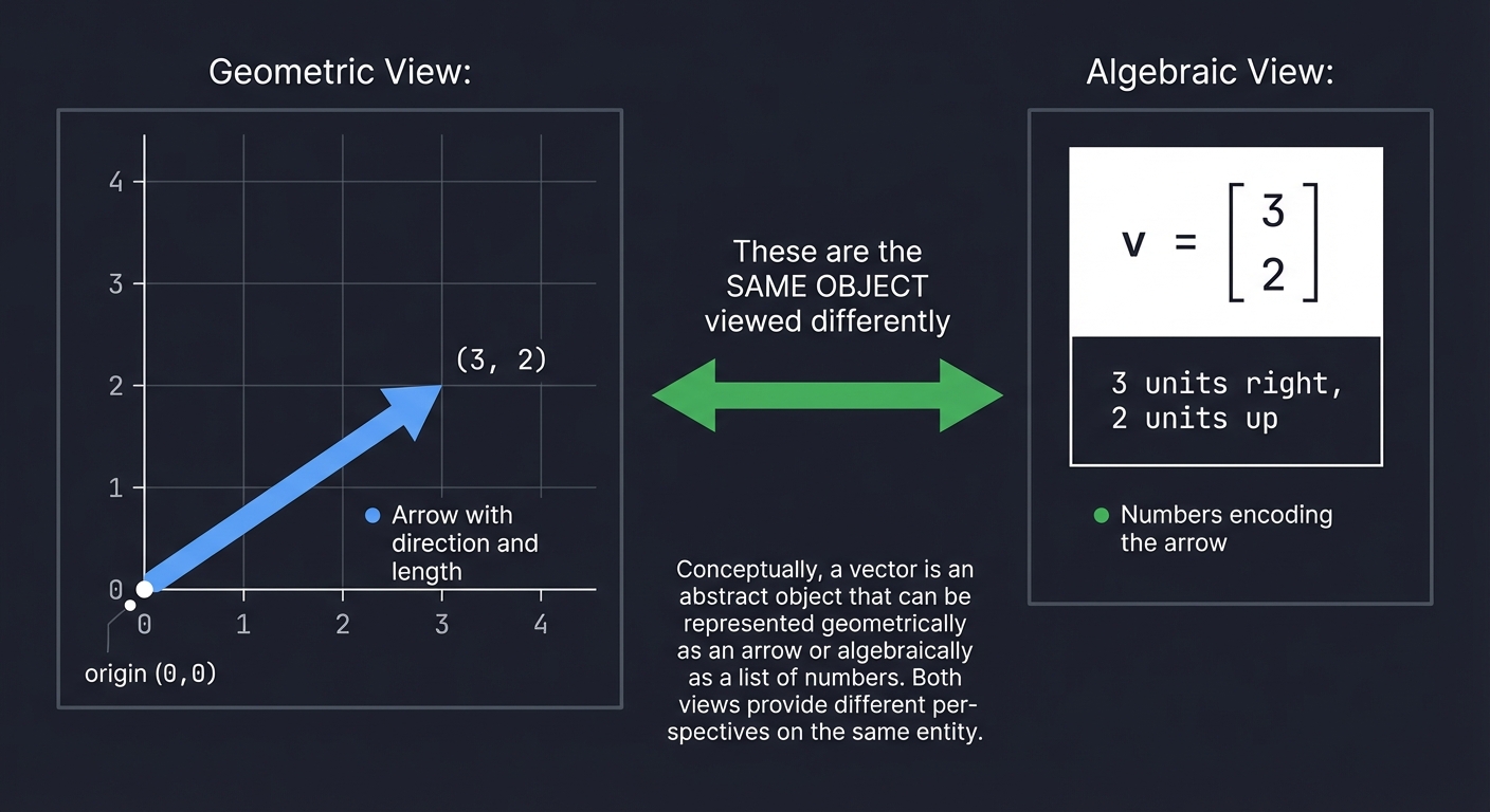
The deep insight: These are the same object viewed differently. The numbers [3, 2] ENCODE the arrow. Change the numbers, change the arrow.
Vector Operations
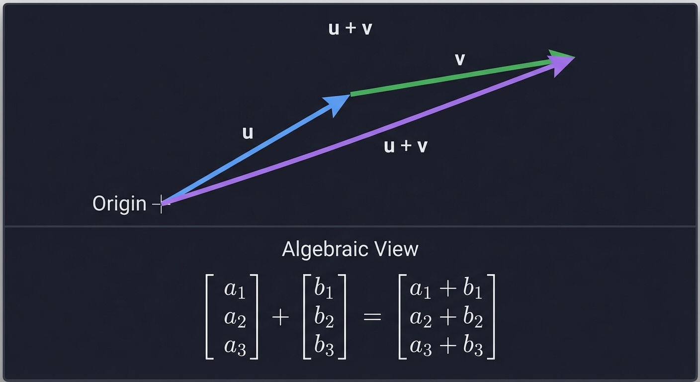
Addition - Placing arrows head-to-tail:
     u + v
      ↗
     /
    v
   ↗
  /
 u→

Algebraically: [a₁]   [b₁]   [a₁ + b₁]
               [a₂] + [b₂] = [a₂ + b₂]
               [a₃]   [b₃]   [a₃ + b₃]
Scalar Multiplication - Stretching or shrinking:
2v means: same direction, twice the length
-v means: opposite direction, same length

Algebraically: k × [a₁]   [k × a₁]
                   [a₂] = [k × a₂]
                   [a₃]   [k × a₃]
Magnitude (Length):
||v|| = √(v₁² + v₂² + v₃²)

This is just the 3D Pythagorean theorem!
Unit Vectors - Direction without magnitude:
v̂ = v / ||v||    (normalized vector, length = 1)

Every direction in space can be represented by a point on the unit sphere.
The Dot Product - Measuring Alignment
The dot product measures how much two vectors point in the same direction:
u · v = u₁v₁ + u₂v₂ + u₃v₃ = ||u|| ||v|| cos(θ)

Where θ is the angle between them.
Key insight:
- If u · v > 0: vectors point generally the same way (θ < 90°)
- If u · v = 0: vectors are perpendicular (θ = 90°)
- If u · v < 0: vectors point generally opposite ways (θ > 90°)
Projection - Finding how much of u lies in the direction of v:
        u
       ↗
      /
     /θ
    •─────────→ v
    ├─────┤
    proj_v(u)

proj_v(u) = (u · v / ||v||²) × v
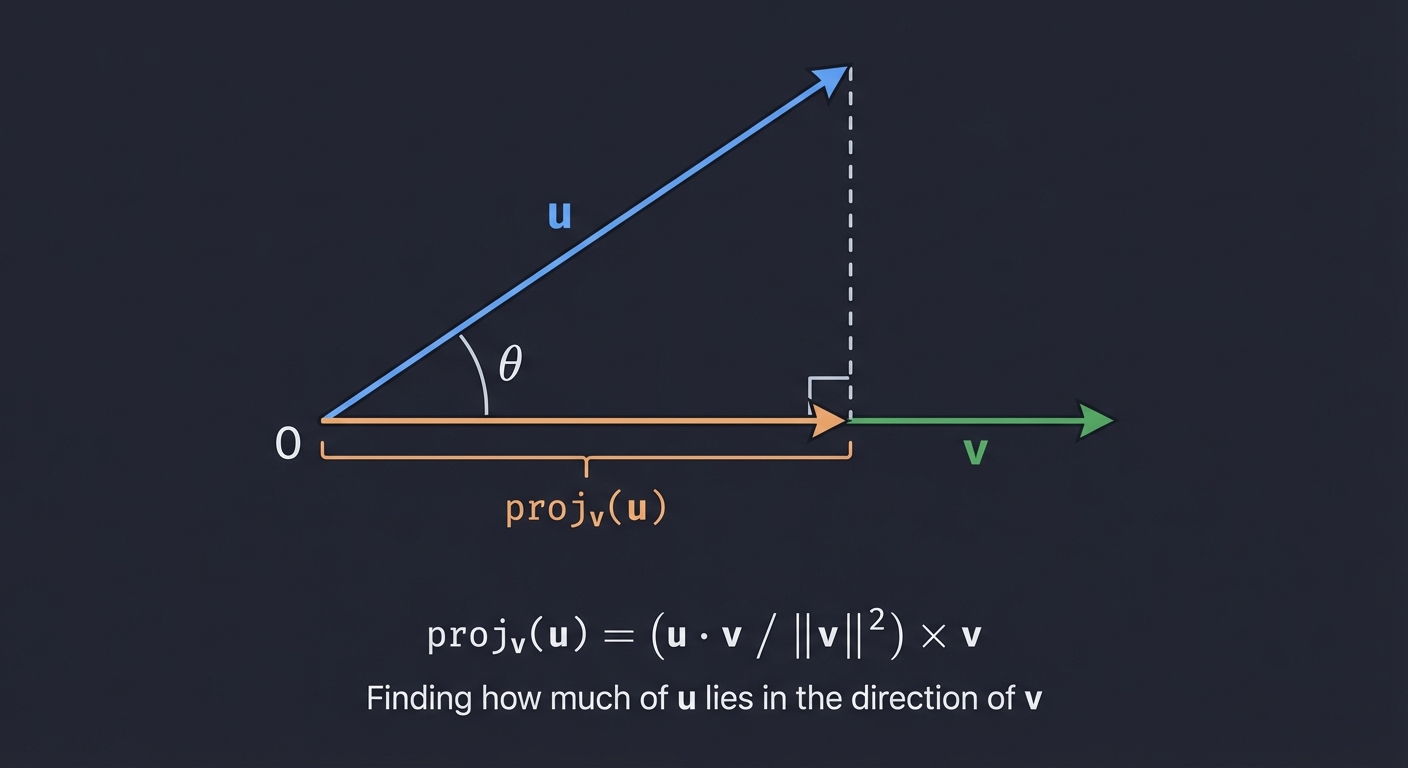
This is crucial for lighting calculations, collision detection, and camera math.
The Cross Product - Finding Perpendiculars (3D Only)
The cross product creates a vector perpendicular to both inputs:
u × v = [u₂v₃ - u₃v₂]
        [u₃v₁ - u₁v₃]    ← This vector is ⊥ to both u and v
        [u₁v₂ - u₂v₁]

Magnitude: ||u × v|| = ||u|| ||v|| sin(θ) = area of parallelogram
Right-hand rule: Point fingers along u, curl toward v, thumb points in u × v direction.
Uses in 3D graphics:
- Computing surface normals
- Determining face orientation (front vs back)
- Building coordinate frames
Part 2: Matrices as Transformations
The Core Insight
A matrix is not just a grid of numbers—it’s a transformation machine. When you multiply a matrix by a vector, you’re asking: “Where does this vector go under this transformation?”
[a b] × [x] = [ax + by]
[c d]   [y]   [cx + dy]

The input vector [x, y] gets transformed to output [ax + by, cx + dy]
The columns of a matrix tell you where the basis vectors go:
     [a b]
M =  [c d]

Column 1 [a, c] = where the x-axis unit vector [1, 0] lands
Column 2 [b, d] = where the y-axis unit vector [0, 1] lands
This is the key to understanding all transformations!
Building Transformation Matrices
Scaling Matrix:
To scale by sx in x and sy in y:

[sx  0 ] × [x] = [sx·x]
[0   sy]   [y]   [sy·y]

The x-axis stretches by sx, y-axis by sy.
In 3D:
[sx  0   0 ]
[0   sy  0 ]
[0   0   sz]
Rotation Matrices:
Rotation by angle θ counterclockwise around the origin in 2D:
[cos(θ)  -sin(θ)]
[sin(θ)   cos(θ)]

Where does [1, 0] go? To [cos(θ), sin(θ)] - a point on the unit circle!
Where does [0, 1] go? To [-sin(θ), cos(θ)] - 90° ahead on the unit circle!
In 3D, we rotate around axes:
Rotation around X-axis (Rx):
[1    0        0    ]
[0    cos(θ)  -sin(θ)]
[0    sin(θ)   cos(θ)]

The x-axis stays fixed; y and z axes rotate in the y-z plane.
Rotation around Y-axis (Ry):
[cos(θ)   0   sin(θ)]
[0        1   0     ]
[-sin(θ)  0   cos(θ)]

The y-axis stays fixed; x and z axes rotate in the x-z plane.
Note the sign flip! This preserves right-handedness.
Rotation around Z-axis (Rz):
[cos(θ)  -sin(θ)  0]
[sin(θ)   cos(θ)  0]
[0        0       1]

The z-axis stays fixed; x and y axes rotate in the x-y plane.
Matrix Multiplication: Composing Transformations
When you multiply matrices, you compose transformations. Order matters!
(M₂ × M₁) × v = M₂ × (M₁ × v)

First M₁ transforms v, then M₂ transforms the result.
Read right-to-left: "apply M₁, then M₂"
Why order matters:
Rotate then Scale ≠ Scale then Rotate

Example: Rotate 45°, then scale x by 2
vs.      Scale x by 2, then rotate 45°

The first stretches along the rotated x-axis.
The second stretches along the original x-axis, then rotates everything.
Build your intuition: transformations are like function composition.
g(f(x)) means “apply f first, then g”
The Identity Matrix and Inverses
Identity Matrix - The “do nothing” transformation:
[1 0 0]
[0 1 0]  × v = v  (input equals output)
[0 0 1]
Inverse Matrix - The “undo” transformation:
M⁻¹ × M = I

If M rotates by 30°, then M⁻¹ rotates by -30°.
If M scales by 2, then M⁻¹ scales by 0.5.
Inverses are essential for camera transforms: “undo” the camera position to get world-to-camera coordinates.
Part 3: Homogeneous Coordinates
The Translation Problem
Rotation and scaling can be represented as matrix multiplication. But translation?
Translate by (tx, ty, tz):

[x]   [x + tx]
[y] → [y + ty]
[z]   [z + tz]

This is ADDITION, not multiplication!
We can't represent it as a 3×3 matrix times a 3D vector.
The Solution: Add a Dimension
Represent 3D points as 4D vectors with w=1:
3D point (x, y, z) → 4D homogeneous coordinates [x, y, z, 1]
Now translation becomes a matrix:
[1  0  0  tx]   [x]   [x + tx]
[0  1  0  ty] × [y] = [y + ty]
[0  0  1  tz]   [z]   [z + tz]
[0  0  0  1 ]   [1]   [1     ]
All transformations are now 4×4 matrices that we can multiply together!
Combined transformation matrix:
[r₁₁  r₁₂  r₁₃  tx]
[r₂₁  r₂₂  r₂₃  ty]   = Rotation/Scale (3×3 block) + Translation (column)
[r₃₁  r₃₂  r₃₃  tz]
[0    0    0    1 ]
What Does the W Coordinate Mean?
- w = 1: This is a point in space
- w = 0: This is a direction (vector) - translation doesn’t affect it!
- w = anything else: Divide by w to get the actual point (projective division)
This last property is key for perspective projection.
Part 4: Projection - From 3D to 2D
Orthographic Projection (No Perspective)
Simply drop the z-coordinate:
[1  0  0  0]   [x]   [x]
[0  1  0  0] × [y] = [y]
[0  0  0  0]   [z]   [0]
[0  0  0  1]   [1]   [1]
Objects far away appear the same size as nearby objects. Useful for CAD, 2D games, or side views.
Perspective Projection (Realistic Depth)
In reality, distant objects appear smaller. The key insight:
If you hold your thumb at arm's length, it looks about the same size
as a car 100 feet away. Why?

Because your eye sees ANGLES, not sizes.
An object twice as far appears half as large.
The perspective projection:
screen_x = x / z  (divide by depth)
screen_y = y / z
As a matrix with near plane d:
[1  0  0   0]   [x]   [x ]
[0  1  0   0] × [y] = [y ]
[0  0  1   0]   [z]   [z ]
[0  0  1/d 0]   [1]   [z/d]

After dividing by w (which is now z/d):
x' = x / (z/d) = dx/z
y' = y / (z/d) = dy/z
The perspective divide (dividing by w) makes things farther from the camera appear smaller.
The Full Projection Pipeline
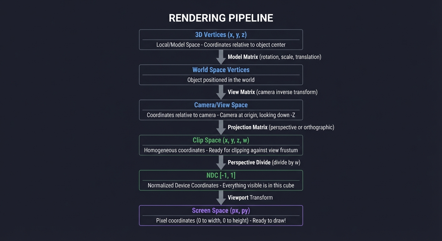
Model Space → World Space → Camera Space → Clip Space → NDC → Screen Space

1. Model Transform: Position object in world
2. View Transform: Convert to camera-relative coordinates
3. Projection Transform: Apply perspective/orthographic
4. Perspective Divide: Divide x,y,z by w
5. Viewport Transform: Map to screen pixels
Part 5: Change of Basis - Camera Transforms
What is a Basis?
A basis is a set of vectors that define a coordinate system. The standard basis:
x-axis: [1, 0, 0]
y-axis: [0, 1, 0]
z-axis: [0, 0, 1]
A camera has its own basis:
right:   points right from camera's view
up:      points up from camera's view
forward: points where camera is looking (or opposite, depending on convention)
View Matrix: World to Camera Space
To render from a camera’s perspective, transform everything into the camera’s coordinate system.
Camera Properties:
- Position: where the camera is (eye)
- Target: what it’s looking at (center)
- Up direction: which way is up (up)
Building the View Matrix:
- Compute camera axes:
forward = normalize(center - eye) // or reverse, depends on convention right = normalize(forward × up) camera_up = right × forward // recompute to ensure orthogonal - Build rotation matrix (columns are camera axes):
[right.x right.y right.z 0] [camera_up.x camera_up.y camera_up.z 0] [-forward.x -forward.y -forward.z 0] // negative forward for right-handed [0 0 0 1] - Translate to camera position (negate eye):
View = RotationMatrix × TranslationMatrix(-eye)
The view matrix answers: “Where is each world point relative to the camera?”
Project Specification
What You’re Building
A software rasterizer that:
- Loads or defines 3D geometry (vertices and edges/faces)
- Applies transformations (rotation, scaling, translation)
- Projects 3D coordinates to 2D screen coordinates
- Renders wireframe output to a display or image file
Minimum Requirements
- Define 3D vertices and edges for at least a cube
- Implement vector operations (add, subtract, scale, dot, cross, normalize)
- Implement 4x4 matrix multiplication
- Build rotation matrices for X, Y, Z axes
- Build scaling and translation matrices
- Compose multiple transformations
- Implement perspective projection
- Map projected coordinates to screen pixels
- Render wireframe to screen or image
- Allow interactive rotation via keyboard input
Stretch Goals
- Load OBJ files for arbitrary models
- Implement camera movement (WASD controls)
- Add backface culling (don’t draw faces pointing away)
- Implement Z-buffer for proper depth ordering
- Add flat shading using surface normals and lighting
Solution Architecture
Data Structures
Vec3:
    x, y, z: float

Vec4:
    x, y, z, w: float

Mat4:
    m[4][4]: float (row-major or column-major - pick one and be consistent!)

Vertex:
    position: Vec3

Edge:
    v1_index, v2_index: int

Mesh:
    vertices: array of Vertex
    edges: array of Edge

Camera:
    position: Vec3
    target: Vec3
    up: Vec3
    fov: float
    near, far: float
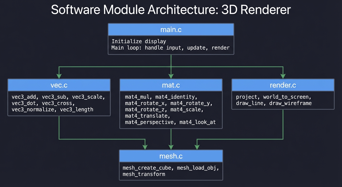
Module Structure
┌─────────────────────────────────────────────────────────────────┐
│                         main.c                                  │
│  - Initialize display                                           │
│  - Main loop: handle input, update, render                     │
└─────────────────────────────────────────────────────────────────┘
                               │
        ┌──────────────────────┼──────────────────────┐
        ▼                      ▼                      ▼
┌──────────────┐      ┌──────────────┐      ┌──────────────┐
│   vec.c      │      │   mat.c      │      │  render.c    │
│              │      │              │      │              │
│ vec3_add     │      │ mat4_mul     │      │ project      │
│ vec3_sub     │      │ mat4_identity│      │ world_to_screen│
│ vec3_scale   │      │ mat4_rotate_x│      │ draw_line    │
│ vec3_dot     │      │ mat4_rotate_y│      │ draw_wireframe│
│ vec3_cross   │      │ mat4_rotate_z│      │              │
│ vec3_normalize│     │ mat4_scale   │      │              │
│ vec3_length  │      │ mat4_translate│     │              │
│              │      │ mat4_perspective│   │              │
│              │      │ mat4_look_at │      │              │
└──────────────┘      └──────────────┘      └──────────────┘
        │                      │                      │
        └──────────────────────┼──────────────────────┘
                               ▼
                      ┌──────────────┐
                      │   mesh.c     │
                      │              │
                      │ mesh_create_cube│
                      │ mesh_load_obj│
                      │ mesh_transform│
                      └──────────────┘
Rendering Pipeline Flow
┌─────────────────────────────────────────────────────────────────────────┐
│                          RENDERING PIPELINE                             │
├─────────────────────────────────────────────────────────────────────────┤
│                                                                         │
│  ┌─────────────┐                                                        │
│  │ 3D Vertices │  Local/Model Space                                     │
│  │ (x, y, z)   │  Coordinates relative to object center                 │
│  └──────┬──────┘                                                        │
│         │                                                               │
│         ▼  Model Matrix (rotation, scale, translation)                  │
│  ┌─────────────┐                                                        │
│  │ World Space │  Object positioned in the world                        │
│  │ Vertices    │                                                        │
│  └──────┬──────┘                                                        │
│         │                                                               │
│         ▼  View Matrix (camera inverse transform)                       │
│  ┌─────────────┐                                                        │
│  │ Camera/View │  Coordinates relative to camera                        │
│  │ Space       │  Camera at origin, looking down -Z                     │
│  └──────┬──────┘                                                        │
│         │                                                               │
│         ▼  Projection Matrix (perspective or orthographic)              │
│  ┌─────────────┐                                                        │
│  │ Clip Space  │  Homogeneous coordinates                               │
│  │ (x, y, z, w)│  Ready for clipping against view frustum               │
│  └──────┬──────┘                                                        │
│         │                                                               │
│         ▼  Perspective Divide (divide by w)                             │
│  ┌─────────────┐                                                        │
│  │ NDC         │  Normalized Device Coordinates                         │
│  │ [-1, 1]     │  Everything visible is in this cube                    │
│  └──────┬──────┘                                                        │
│         │                                                               │
│         ▼  Viewport Transform                                           │
│  ┌─────────────┐                                                        │
│  │ Screen Space│  Pixel coordinates (0 to width, 0 to height)           │
│  │ (px, py)    │  Ready to draw!                                        │
│  └─────────────┘                                                        │
│                                                                         │
└─────────────────────────────────────────────────────────────────────────┘
Phased Implementation Guide
Phase 1: Foundations (Days 1-3)
Goal: Implement vector and matrix math library
Tasks:
- Create
Vec3structure and operations:vec3_add(a, b)→ a + bvec3_sub(a, b)→ a - bvec3_scale(v, s)→ s × vvec3_dot(a, b)→ a · bvec3_cross(a, b)→ a × b-
vec3_length(v)→v -
vec3_normalize(v)→ v /v
-
Create
Vec4for homogeneous coordinates - Create
Mat4structure and operations:mat4_identity()→ Imat4_multiply(A, B)→ A × Bmat4_multiply_vec4(M, v)→ M × v
Verification:
// Test: identity matrix times vector equals vector
Vec4 v = {1, 2, 3, 1};
Mat4 I = mat4_identity();
Vec4 result = mat4_multiply_vec4(I, v);
assert(result.x == 1 && result.y == 2 && result.z == 3);

// Test: rotation by 0 radians equals identity
Mat4 R = mat4_rotate_z(0);
// Should equal identity

// Test: rotation by 2π equals identity (approximately)
Mat4 R = mat4_rotate_z(2 * PI);
// All values should be close to identity
Phase 2: Transformations (Days 4-6)
Goal: Implement all transformation matrices
Tasks:
- Implement rotation matrices:
mat4_rotate_x(angle)- rotation around X axismat4_rotate_y(angle)- rotation around Y axismat4_rotate_z(angle)- rotation around Z axis
- Implement other transforms:
mat4_scale(sx, sy, sz)mat4_translate(tx, ty, tz)
Verification:
// Test: rotating [1, 0, 0] by 90° around Z gives [0, 1, 0]
Vec4 v = {1, 0, 0, 1};
Mat4 R = mat4_rotate_z(PI / 2);
Vec4 result = mat4_multiply_vec4(R, v);
assert(fabs(result.x) < 0.001 && fabs(result.y - 1) < 0.001);

// Test: scaling [1, 2, 3] by 2 gives [2, 4, 6]
Vec4 v = {1, 2, 3, 1};
Mat4 S = mat4_scale(2, 2, 2);
Vec4 result = mat4_multiply_vec4(S, v);
assert(result.x == 2 && result.y == 4 && result.z == 6);

// Test: translation moves the point
Vec4 v = {0, 0, 0, 1};
Mat4 T = mat4_translate(5, 10, 15);
Vec4 result = mat4_multiply_vec4(T, v);
assert(result.x == 5 && result.y == 10 && result.z == 15);
Phase 3: 2D Rendering (Days 7-9)
Goal: Draw lines on screen
Tasks:
- Set up a display/framebuffer:
- Use SDL2, or
- Write to a PPM image file, or
- Use ncurses for terminal rendering
-
Implement
draw_pixel(x, y, color) - Implement
draw_line(x1, y1, x2, y2, color):- Use Bresenham’s algorithm or DDA
- Test with 2D shapes:
- Draw a square
- Draw a triangle
Verification:
- Lines should appear continuous (no gaps)
- Diagonal lines should look correct
- Lines should clip to screen boundaries
Phase 4: 3D Cube with Orthographic Projection (Days 10-12)
Goal: Render a 3D cube as 2D wireframe (no perspective)
Tasks:
- Define cube vertices:
Vec3 cube_vertices[8] = { {-1, -1, -1}, {1, -1, -1}, {1, 1, -1}, {-1, 1, -1}, // back face {-1, -1, 1}, {1, -1, 1}, {1, 1, 1}, {-1, 1, 1} // front face }; -
Define cube edges (pairs of vertex indices)
- Implement orthographic projection:
- Simply use x and y, ignore z
- Map to screen coordinates
- Draw all edges
Verification:
- Cube should appear as a square (orthographic view)
- All 12 edges should be visible
- Rotating should show 3D structure
Phase 5: Rotation and Animation (Days 13-15)
Goal: Rotate the cube smoothly
Tasks:
-
Create a rotation angle variable that increases each frame
- Build model matrix:
Mat4 model = mat4_multiply(mat4_rotate_y(angle_y), mat4_rotate_x(angle_x)); -
Transform all vertices before projection
- Add keyboard input:
- Arrow keys or WASD to control rotation angles
Verification:
- Cube should rotate smoothly
- Rotation should be around the cube’s center
- Multiple rotations should compose correctly
Phase 6: Perspective Projection (Days 16-18)
Goal: Add realistic depth perception
Tasks:
- Implement perspective projection matrix:
Mat4 mat4_perspective(float fov, float aspect, float near, float far); -
Apply projection after model transform
-
Perform perspective divide (divide x, y, z by w)
- Map from NDC [-1, 1] to screen coordinates
Verification:
- Near edges should appear larger than far edges
- Cube should look 3D, not flat
- Moving cube away (increasing z) should make it smaller
Phase 7: Camera System (Days 19-21)
Goal: Implement a movable camera
Tasks:
- Implement
mat4_look_at(eye, center, up):- Compute forward, right, up vectors
- Build view matrix
-
Add camera position and orientation variables
-
Pipeline: model → view → projection → divide → screen
- Add camera controls:
- WASD to move camera position
- Mouse or arrow keys to rotate view
Verification:
- Moving camera back should make objects smaller
- Rotating camera should show different sides
- Camera up should always point up on screen
Testing Strategy
Unit Tests
- Vector operations:
- Dot product of perpendicular vectors = 0
- Cross product is perpendicular to both inputs
- Normalized vector has length 1
- Matrix operations:
- A × I = A
- (A × B) × C = A × (B × C)
- Rotation matrix has determinant 1
- Transformation correctness:
- Rotate [1,0,0] by 90° around Z = [0,1,0]
- Scale by 2 doubles all coordinates
- Translate by [1,2,3] adds [1,2,3]
Visual Tests
- Static cube: Should show proper 3D shape
- Rotation: Should be smooth, centered on cube
- Perspective: Near face larger than far face
- Camera: WASD movement feels natural
Edge Cases
- Rotation by exactly 0, 90, 180, 360 degrees
- Camera at origin looking at distant object
- Very small and very large scale factors
- Objects behind the camera (should not render)
Common Pitfalls and Debugging
Matrix Multiplication Order
Symptom: Transformations seem wrong or backwards
Cause: Multiplying matrices in wrong order
Fix: Remember that M₂ × M₁ × v applies M₁ first, then M₂. Read right-to-left.
Row-Major vs Column-Major
Symptom: Everything is transposed or transformations fail
Cause: Confusion between row-major (C arrays) and column-major (OpenGL) storage
Fix: Pick one convention and stick with it. If using OpenGL-style math, you may need to transpose.
Gimbal Lock
Symptom: Rotation “locks up” at certain orientations
Cause: Using Euler angles (rotate X, then Y, then Z)
Fix: For this project, it’s acceptable. For production, use quaternions.
Division by Zero in Projection
Symptom: Vertices at z=0 cause crashes or NaN
Cause: Perspective divide by z when z=0
Fix: Clip vertices behind the near plane before perspective divide.
Winding Order Issues
Symptom: Some faces appear “inside out” or culling removes wrong faces
Cause: Inconsistent vertex ordering
Fix: Ensure all faces use consistent clockwise or counterclockwise winding.
Coordinate System Confusion
Symptom: Objects appear in wrong position or flipped
Cause: Mixing left-handed and right-handed coordinate systems
Fix: Document your convention. OpenGL uses right-handed (Z points out of screen).
Debugging Techniques
-
Print intermediate values: After each transform, print a sample vertex to trace the pipeline.
-
Visualize transform matrices: Print the 4×4 matrix—check for reasonable values.
-
Test with known inputs: Rotate [1, 0, 0] by 90° should give [0, 1, 0].
-
Simplify: Remove all transforms and just project raw vertices. Does that work?
-
Disable perspective: Use orthographic first to eliminate one variable.
-
Draw axes: Render X, Y, Z axes to understand orientation.
Extensions and Challenges
Beginner Extensions
- Load OBJ files for complex models
- Multiple objects with independent transforms
- Simple animation (rotating planets, etc.)
Intermediate Extensions
- Flat shading with ambient + diffuse lighting
- Depth buffer (Z-buffer) for proper occlusion
- Texture mapping with UV coordinates
- Clipping against view frustum
Advanced Extensions
- Gouraud shading (per-vertex lighting, interpolate)
- Phong shading (per-pixel lighting)
- Shadow mapping
- Implement quaternions for rotation
Real-World Connections
Game Engines
Every 3D game uses exactly this pipeline. Understanding it lets you:
- Debug rendering issues
- Optimize draw calls
- Implement custom shaders
- Understand GPU architecture
Graphics APIs
OpenGL, Vulkan, DirectX, Metal—they all use this math:
- Vertex shaders transform vertices (model × view × projection)
- Fragment shaders handle per-pixel operations
- The fixed-function pipeline you’re implementing is what GPUs do in hardware
Computer Vision
The same matrices handle:
- Camera calibration (intrinsic and extrinsic matrices)
- Augmented reality (overlay 3D on video)
- Structure from motion (3D from 2D images)
Robotics
Robot arm kinematics uses transformation chains:
- Each joint is a rotation transformation
- Forward kinematics: multiply transformations
- Inverse kinematics: solve for joint angles
Self-Assessment Checklist
Conceptual Understanding
- I can explain what a matrix column represents geometrically
- I know why matrix multiplication order matters
- I can derive a rotation matrix from first principles
- I understand why we use 4×4 matrices for 3D transforms
- I can explain perspective projection without looking at notes
- I understand change of basis and view matrices
Practical Skills
- I implemented all transform matrices from scratch
- My cube rotates smoothly with correct perspective
- I can move a camera through the scene
- I can debug transformation issues by inspecting matrices
- I can trace a vertex through the entire pipeline
Teaching Test
Can you explain to someone else:
- Why we need homogeneous coordinates?
- How does perspective make things look 3D?
- What does the view matrix actually do?
- Why does rotation order matter?
Resources
Primary
- “Computer Graphics from Scratch” by Gabriel Gambetta - The definitive resource
- 3Blue1Brown: Essence of Linear Algebra - Geometric intuition (YouTube)
Reference
- “3D Math Primer for Graphics and Game Development” by Dunn & Parberry
- Scratchapixel.com - Detailed rendering tutorials
- “Real-Time Rendering” by Akenine-Möller - Advanced reference
Tools
- GeoGebra 3D Calculator - Visualize transformations
- GLM (OpenGL Mathematics) - C++ math library for reference
- Desmos - 2D graphing and matrix visualization
When you complete this project, you will have internalized the mathematical foundations of all 3D graphics. Every game you play, every movie effect you see, every VR experience—you’ll understand the matrices that make it possible.