NeoTrellis M4 Mastery - Real World Projects
Goal: Completely master the Adafruit NeoTrellis M4—from basic button/LED interactions in CircuitPython, through Arduino audio synthesis, to bare-metal C programming that directly manipulates the ATSAMD51’s registers. You’ll understand the ARM Cortex-M4 architecture, I2C/SPI communication, DAC audio generation, accelerometer physics, USB protocols, and real-time embedded programming. By the end, you’ll be able to build professional MIDI controllers, synthesizers, interactive instruments, and understand exactly what happens at every level of the hardware stack.
Introduction
The Adafruit NeoTrellis M4 is a professional-grade embedded development board that combines a 4×8 button matrix, 32 RGB LEDs (NeoPixels), dual 12-bit DACs for stereo audio, a 3-axis accelerometer, and native USB MIDI—all powered by a 120 MHz ARM Cortex-M4F microcontroller with hardware floating-point and DSP capabilities.
What Is the NeoTrellis M4?
At its core, the NeoTrellis M4 is an audio-visual controller and embedded systems learning platform built around Microchip’s ATSAMD51J19 microcontroller. Unlike simple development boards, it integrates multiple real-world subsystems that professional music hardware uses:
- Input: 32-button tactile matrix with anti-ghosting diodes + 3-axis ADXL343 accelerometer
- Output: 32 addressable WS2812B RGB LEDs + dual 12-bit DAC stereo audio @ 500 KSPS
- Communication: Native USB (MIDI/Serial/Mass Storage) + I2C/SPI expansion headers
- Storage: 512 KB Flash + 192 KB SRAM + 8 MB external QSPI flash for samples/files
Sources:
What Problem Does It Solve?
The Learning Problem: Traditional embedded education separates concepts into isolated “blinky LED” examples that never connect to real-world applications. You learn GPIO, but never audio. You learn timers, but never build an instrument.
The NeoTrellis M4 Solves This By:
- Integrating all major embedded subsystems (GPIO, DAC/ADC, DMA, USB, I2C, timers) in one physical device
- Providing multiple abstraction levels (CircuitPython → Arduino → Bare-Metal C) so you can learn concepts before optimization
- Delivering immediate feedback—press a button, hear a sound, see an LED—no oscilloscope required for basic validation
- Matching commercial product architecture—skills transfer directly to MIDI controller, synthesizer, and IoT device development
What You’ll Build Across These Projects
By completing this sprint, you’ll build:
- Interactive Instruments: MIDI controllers, polyphonic synthesizers, drum machines, step sequencers
- Audio-Visual Applications: FFT spectrum analyzers, audio visualizers, motion-reactive light shows
- Low-Level Drivers: Bare-metal NeoPixel driver, I2C accelerometer driver, USB bootloader
- Professional Tools: DAW controller with MIDI mapping, sample players, theremins
Each project produces a working, usable device that demonstrates specific embedded concepts through hands-on implementation.
Scope & Boundaries
What’s Included:
- ✅ CircuitPython rapid prototyping (Projects 1-5)
- ✅ Arduino audio synthesis with PJRC Audio library (Projects 6-10)
- ✅ Bare-metal C register programming (Projects 11-15)
- ✅ Full integration projects (Projects 16-18)
- ✅ ARM Cortex-M4 architecture, interrupts, DMA, peripherals
- ✅ Real-time audio DSP fundamentals
- ✅ USB MIDI protocol implementation
What’s Explicitly Out of Scope:
- ❌ Advanced DSP theory (FFT internals, filter design)
- ❌ PCB design or hardware modifications beyond optional extensions
- ❌ RTOS integration (FreeRTOS, Zephyr)
- ❌ Wireless communication (Bluetooth, WiFi)—focus is on core embedded concepts
- ❌ Production firmware (bootloader security, OTA updates, fail-safe recovery)
The System Architecture at a Glance
                         NeoTrellis M4 Architecture
┌────────────────────────────────────────────────────────────────────────┐
│                                                                        │
│   ┌─────────────────────────────────────────────────────────────────┐  │
│   │                    ATSAMD51J19 (ARM Cortex-M4)                  │  │
│   │                                                                 │  │
│   │  ┌─────────────┐  ┌─────────────┐  ┌─────────────────────────┐  │  │
│   │  │   120 MHz   │  │  512KB      │  │   Hardware DSP          │  │  │
│   │  │   Core      │  │  Flash      │  │   - FPU                 │  │  │
│   │  │             │  │             │  │   - Single-cycle MAC    │  │  │
│   │  └─────────────┘  └─────────────┘  │   - SIMD instructions   │  │  │
│   │                                    └─────────────────────────┘  │  │
│   │  ┌─────────────┐  ┌─────────────┐  ┌─────────────────────────┐  │  │
│   │  │  192KB      │  │  8MB        │  │   Peripherals           │  │  │
│   │  │  SRAM       │  │  External   │  │   - 2x 12-bit DAC       │  │  │
│   │  │             │  │  Flash      │  │   - 16x 12-bit ADC      │  │  │
│   │  └─────────────┘  └─────────────┘  │   - 6x SERCOM           │  │  │
│   │                                    │   - USB Native          │  │  │
│   │                                    │   - DMA Controller      │  │  │
│   └────────────────────────────────────┴─────────────────────────┴──┘  │
│                            │                                           │
│                            │ I2C/GPIO                                  │
│         ┌──────────────────┼──────────────────┐                        │
│         │                  │                  │                        │
│         ▼                  ▼                  ▼                        │
│   ┌───────────┐      ┌───────────┐      ┌───────────┐                  │
│   │  ADXL343  │      │  32x      │      │  Button   │                  │
│   │  3-Axis   │      │  NeoPixel │      │  Matrix   │                  │
│   │  Accel.   │      │  LEDs     │      │  4x8      │                  │
│   │  (I2C)    │      │  (WS2812) │      │  Dioded   │                  │
│   └───────────┘      └───────────┘      └───────────┘                  │
│                                                                        │
│   ┌───────────────────────────────────────────────────────────────┐    │
│   │                        Audio Subsystem                        │    │
│   │  ┌──────────┐    ┌──────────┐    ┌──────────────────────┐    │    │
│   │  │ Dual DAC │───▶│ TRRS     │◀───│ MAX4466 Mic Preamp   │    │    │
│   │  │ L/R Out  │    │ Jack     │    │ (ADC Input)          │    │    │
│   │  └──────────┘    └──────────┘    └──────────────────────┘    │    │
│   └───────────────────────────────────────────────────────────────┘    │
│                                                                        │
│   ┌─────────────────┐                    ┌─────────────────────────┐   │
│   │   USB Native    │                    │   4-JST Expansion       │   │
│   │   - CDC Serial  │                    │   - I2C/ADC/UART        │   │
│   │   - USB MIDI    │                    │   - 3.3V Power          │   │
│   │   - Mass Storage│                    └─────────────────────────┘   │
│   └─────────────────┘                                                  │
│                                                                        │
└────────────────────────────────────────────────────────────────────────┘
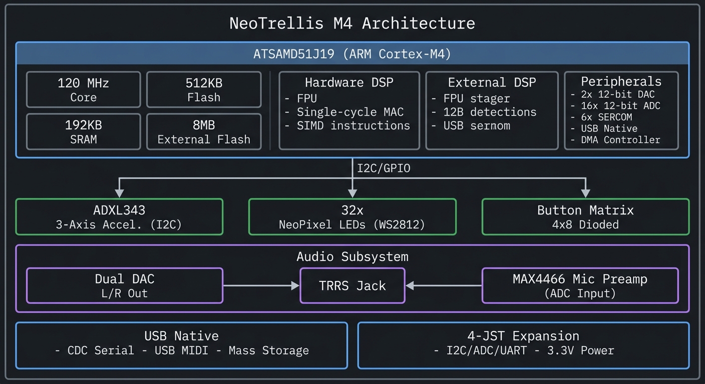
Key Insight: Every layer of abstraction (Python → C++ → Bare C) controls the same hardware. Understanding all three levels gives you the ability to prototype rapidly, optimize selectively, and debug fearlessly.
How to Use This Guide
This guide is structured as a theory-first, project-based sprint. Theory builds mental models; projects apply them.
Reading Strategy
For Beginners (New to Embedded Systems):
- Read the entire Theory Primer (next section) before starting any project
- Complete Projects 1-5 in order using CircuitPython
- Return to the primer when concepts feel unclear
- Move to Arduino projects (6-10) only after solid understanding of CircuitPython
For Intermediate (Have Arduino Experience):
- Skim Theory Primer, focus on ARM architecture and audio sections
- Start with Project 1 to understand the board, then jump to Project 6 (Arduino synthesis)
- Read bare-metal sections when ready for Projects 11-15
For Advanced (Want Bare-Metal Expertise):
- Read Theory Primer sections on ARM Cortex-M4, Memory Mapping, DMA
- Complete Projects 1-2 quickly for board familiarization
- Focus on Projects 11-18 (bare-metal and integration)
Working Through Projects
Each project follows this structure:
- Real World Outcome: What you’ll see/hear when done (with exact CLI output or behavior)
- Core Question: The fundamental concept this project answers
- Prerequisites: Concepts you must understand first (with book references)
- Design Questions: Guide your implementation thinking
- Thinking Exercise: Mental model building before coding
- Layered Hints: Progressive help when stuck (no complete code)
- Common Pitfalls: Debug guide for likely issues
- Definition of Done: Explicit completion criteria
Never skip the “Thinking Exercise”—it builds intuition that code alone cannot.
Book Integration
This guide references specific chapters from books you likely own (see BOOKS.md). The pattern:
- Theory Primer → Read relevant book chapters for deep understanding
- Project Prerequisites → Consult books for specific techniques
- Debugging → Use books for troubleshooting strategies
You don’t need to read entire books—targeted chapter reading is sufficient.
Lab Setup Recommendations
Minimum Viable Setup:
- NeoTrellis M4 with buttons and enclosure
- USB-C cable
- Headphones or powered speakers (3.5mm)
- Computer (Windows/macOS/Linux)
Recommended Additions:
- Logic analyzer or oscilloscope (Projects 11-15)
- USB MIDI-capable DAW (GarageBand, Ableton Live Lite, REAPER)
- Multimeter (voltage/continuity checking)
Optional (Advanced Projects):
- J-Link or Atmel-ICE debugger
- External I2C/SPI devices for expansion projects
Time Management
Budget your time realistically:
| Project Type | Time per Project | Skill Focus |
|---|---|---|
| CircuitPython (1-5) | 4-8 hours | Concepts, rapid iteration |
| Arduino Audio (6-10) | 8-16 hours | DSP, libraries, performance |
| Bare-Metal C (11-15) | 12-24 hours | Registers, timing, drivers |
| Integration (16-18) | 20-40 hours | System design, debugging |
Total sprint: 3-4 months if working 4-6 hours/week.
When You Get Stuck
- Check Definition of Done: Are you solving the right problem?
- Review Thinking Exercise: Did you understand before coding?
- Read Common Pitfalls: Your issue is likely listed
- Consult Book References: Theory gaps often cause implementation struggles
- Add Serial Debugging: Print timestamps, values, state transitions
- Use Hints Progressively: Read Hint 1, try again; if stuck, read Hint 2…
Do NOT skip to Hint 4 immediately—the learning happens in the struggle.
Prerequisites & Background Knowledge
Essential Prerequisites (Must Have)
Before starting these projects, you should:
Programming Foundations:
- Basic Python syntax (variables, loops, functions, classes)
- Understanding of bits and bytes (binary, hexadecimal)
- Familiarity with arrays/lists and basic data structures
- Boolean logic and bit manipulation (AND, OR, XOR, shifts)
Hardware Basics:
- Know what GPIO (General Purpose Input/Output) means
- Understand voltage levels (3.3V logic, HIGH/LOW states)
- Can follow a simple wiring diagram
- Recognize basic electronic components (resistor, capacitor, LED)
Development Environment:
- Comfortable with command line/terminal basics
- Can install software packages and libraries
- Have a text editor you’re comfortable with (Mu, VS Code, or similar)
- Understand file paths and directory navigation
Mathematics (for Audio Projects):
- Basic trigonometry (sine, cosine)
- Understand frequency, period, amplitude
- Can read logarithmic scales (decibels)
Recommended Reading: “Computer Systems: A Programmer’s Perspective” by Bryant & O’Hallaron - Ch. 1-2
Helpful But Not Required
You’ll learn these during the projects:
- Prior microcontroller experience (Arduino Uno, Raspberry Pi Pico) → Projects 1-5 teach this
- C programming experience → Introduced progressively in Projects 6-10, required for 11-18
- Knowledge of audio/music concepts (notes, MIDI, synthesis) → Explained in audio project primers
- Understanding of USB protocols → Covered in Theory Primer
- Assembly language → Not required; register-level C is sufficient
Self-Assessment Questions
Before starting, can you answer these?
- Python: What’s the difference between a list and a dictionary? When would you use each?
- Binary: What’s
0xFFin decimal? What’s0b10101010in hexadecimal? - Hardware: If a pin outputs 3.3V, is it HIGH or LOW? What about 0V?
- Timing: How many milliseconds in one second? How many microseconds in one millisecond?
- Logic: What’s
0b1100 & 0b1010in binary? What about0b1100 | 0b1010? - C basics (for Arduino projects): What’s the difference between
int x = 5;andint *x = &y;?
If you struggled with questions 1-5, spend a day reviewing Python and digital logic fundamentals first. If you struggled with question 6, complete CircuitPython projects first, then learn C alongside Arduino projects.
Required Hardware
For all projects in this guide, you need:
- Adafruit NeoTrellis M4 with Enclosure and Buttons Kit Pack (Product 4020)
- Includes mainboard, enclosure, 32 silicone button pads
- Cost: ~$60 USD (2024)
- USB-C cable (for programming and power)
- Headphones or powered speakers (3.5mm TRRS jack for audio projects)
- Computer with USB port (Windows, macOS, or Linux)
Total investment: ~$60-80 (assuming you have a computer and headphones)
Optional But Highly Recommended
These dramatically improve the learning experience:
Software:
- USB-MIDI capable software: Ableton Live Lite (often free with hardware), GarageBand (macOS), REAPER (trial), or VCV Rack (free)
- Serial terminal: Arduino IDE Serial Monitor, Mu Editor REPL, or
screen/minicom
Hardware (for bare-metal projects):
- Logic analyzer or oscilloscope: Verify timing on WS2812B, I2C, UART (~$10-50 for Saleae clones)
- Multimeter: Verify connections, measure voltages (~$15-30)
- J-Link EDU Mini or Atmel-ICE: Hardware debugging for bare-metal C (~$20-60)
Development Environment Setup
For CircuitPython (Projects 1-5):
- Download CircuitPython firmware for Trellis M4:
- Visit circuitpython.org
- Download latest stable release (9.x as of 2024)
- Install firmware:
- Double-tap RESET button on NeoTrellis M4
- Board mounts as
TRELLIS_BOOTdrive - Drag
.UF2file onto drive - Board reboots as
CIRCUITPYdrive
- Install editor:
- Mu Editor (beginner-friendly): codewith.mu
- VS Code with CircuitPython extension (advanced)
- Install libraries:
- Download Adafruit CircuitPython Library Bundle
- Copy required folders to
CIRCUITPY/lib/:adafruit_neotrellis,adafruit_seesaw,adafruit_adxl34x
Verification:
# In Mu Editor REPL:
import board
dir(board)  # Should show NEOPIXEL, SDA, SCL, etc.
For Arduino (Projects 6-10):
-
Install Arduino IDE 2.x: arduino.cc
- Add SAMD board support:
- File → Preferences → Additional Board Manager URLs:
https://adafruit.github.io/arduino-board-index/package_adafruit_index.json - Tools → Board Manager → Search “Adafruit SAMD” → Install
- File → Preferences → Additional Board Manager URLs:
- Select board:
- Tools → Board → Adafruit SAMD Boards → Adafruit NeoTrellis M4
- Install libraries (Tools → Manage Libraries):
Adafruit_NeoTrellisAdafruit_NeoPixelAdafruit_ADXL343Adafruit_SAMD_Audio(for Projects 6-10)pjrc_Audio(Adafruit fork for SAMD51)
Verification:
// Upload this sketch:
void setup() {
  Serial.begin(115200);
  while(!Serial);
  Serial.println("NeoTrellis M4 Ready!");
}
void loop() {}
For Bare-Metal C (Projects 11-15):
- Install ARM GCC toolchain:
- macOS:
brew install arm-none-eabi-gcc - Linux:
sudo apt install gcc-arm-none-eabi - Windows: ARM GNU Toolchain
- macOS:
- Install flasher (choose one):
- BOSSA (drag-and-drop): github.com/shumatech/BOSSA
- OpenOCD (advanced):
brew install openocd/apt install openocd
- Download SAMD51 resources:
- Datasheet: Microchip ATSAMD51 Family Datasheet
- CMSIS headers: SAMD51 Device Family Pack
- Optional: Install SEGGER J-Link software for hardware debugging
Verification:
arm-none-eabi-gcc --version  # Should show version 10.x or newer
bossac --help                # Should show BOSSA flasher options
Power & Safety Rules
Critical Safety Practices:
- Unplug before wiring: Disconnect USB when adding external components or modifying circuits
- Avoid shorts: The board has a 500mA resettable fuse, but repeated trips slow debugging
- NeoPixel wire length: Keep data wire short (<6 inches) to reduce timing errors and reflections
- USB power limits: If connecting power-hungry peripherals, use a powered USB hub
- Static protection: Touch grounded metal before handling board to discharge static
Common Mistakes That Damage Hardware:
- ❌ Connecting 5V signals to 3.3V pins (use level shifter)
- ❌ Shorting power rails during breadboard wiring
- ❌ Hot-plugging I2C devices while powered (can corrupt bus)
- ❌ Exceeding 3.3V on any GPIO (instant damage)
Time Investment Reality Check
Be realistic about learning timelines:
| Learning Path | Time Commitment | Prerequisites |
|---|---|---|
| CircuitPython only (Projects 1-5) | 2-3 weeks @ 6hrs/week | Python basics |
| Arduino + Audio (Projects 6-10) | 4-6 weeks @ 6hrs/week | C++ basics |
| Bare-Metal C (Projects 11-15) | 8-12 weeks @ 6hrs/week | Strong C, some assembly |
| Complete Mastery (All 18 projects) | 3-4 months @ 6hrs/week | All of the above + patience |
Important Reality Check:
- Don’t rush. Embedded debugging takes longer than application programming.
- Expect failures. LEDs will blink wrong, audio will glitch, I2C will NACK. This is normal.
- Read datasheets. The ATSAMD51 datasheet has 1700+ pages. You’ll reference it constantly for bare-metal work.
- Build incrementally. Every project has intermediate milestones. Celebrate small wins.
If you can only dedicate 2-3 hours/week, budget 6-8 months for complete mastery.
Big Picture / Mental Model
Before diving into theory, understand the conceptual layers of embedded audio-visual systems.
The Three-Layer Embedded Stack
Every embedded system has three conceptual layers. Understanding their relationship is key to debugging and optimization.
┌──────────────────────────────────────────────────────────────────┐
│                    APPLICATION LAYER                             │
│  "What" - The logic, algorithms, and behavior                    │
│  Example: "Play a C major chord when buttons 0,4,7 are pressed"  │
│                                                                  │
│  Tools: CircuitPython, Arduino libraries, high-level C code     │
│  Characteristics: Readable, portable, slower                     │
└────────────────┬─────────────────────────────────────────────────┘
                 │ API calls (digitalWrite, analogWrite, etc.)
                 ▼
┌──────────────────────────────────────────────────────────────────┐
│                    ABSTRACTION LAYER                             │
│  "How" - Libraries, drivers, hardware abstraction layer (HAL)    │
│  Example: NeoPixel.show() → DMA setup → bit-banging timing      │
│                                                                  │
│  Tools: Arduino libraries, CircuitPython modules, vendor SDKs   │
│  Characteristics: Hides complexity, handles edge cases           │
└────────────────┬─────────────────────────────────────────────────┘
                 │ Register writes, interrupt handlers
                 ▼
┌──────────────────────────────────────────────────────────────────┐
│                    HARDWARE LAYER                                │
│  "Where" - Registers, peripherals, electrical signals            │
│  Example: PORT->Group[0].OUTSET.reg = (1 << 10); // Set PA10    │
│                                                                  │
│  Tools: Bare C, assembly, memory-mapped I/O, oscilloscope       │
│  Characteristics: Maximum control, timing precision, complexity  │
└──────────────────────────────────────────────────────────────────┘
Why This Matters:
- CircuitPython operates at Application + Abstraction layers → fast prototyping
- Arduino spans Abstraction + Hardware layers → balance of ease and control
- Bare-Metal C lives at Hardware layer → you write the abstraction
The Learning Path: Start at the top (CircuitPython), understand behavior, then descend to learn how it’s implemented.
The Four Major Subsystems
The NeoTrellis M4 integrates four independent-but-connected subsystems:
                    NeoTrellis M4 Subsystems

┌─────────────────────────────────────────────────────────────────┐
│                                                                 │
│  ┌──────────────────┐         ┌──────────────────┐             │
│  │  INPUT           │         │  PROCESSING      │             │
│  │  ──────          │    ┌───▶│  ──────────      │             │
│  │  • 32 Buttons    │────┤    │  • ARM M4 Core   │             │
│  │  • Accelerometer │    │    │  • 120MHz FPU    │             │
│  │  • Mic Input     │────┘    │  • 192KB SRAM    │             │
│  └──────────────────┘         └────────┬─────────┘             │
│                                        │                        │
│                                        │                        │
│                                        ▼                        │
│  ┌──────────────────┐         ┌──────────────────┐             │
│  │  VISUAL OUTPUT   │    ┌────│  AUDIO OUTPUT    │             │
│  │  ─────────────   │◀───┤    │  ────────────    │             │
│  │  • 32 NeoPixels  │    │    │  • Dual 12-bit   │             │
│  │  • WS2812 800kHz │    │    │    DAC           │             │
│  │  • DMA driven    │    │    │  • Stereo 44.1k  │             │
│  └──────────────────┘    │    │  • DMA driven    │             │
│                          │    └──────────────────┘             │
│                          │                                     │
│                          │    ┌──────────────────┐             │
│                          └───▶│  COMMUNICATION   │             │
│                               │  ─────────────   │             │
│                               │  • USB MIDI      │             │
│                               │  • I2C/SPI       │             │
│                               │  • UART          │             │
│                               └──────────────────┘             │
│                                                                 │
└─────────────────────────────────────────────────────────────────┘
Subsystem Interactions:
- Input → Processing: Button press generates interrupt → CPU reads matrix → Updates application state
- Processing → Visual: Application computes LED colors → DMA transfers to NeoPixel chain
- Processing → Audio: Synthesis algorithm fills buffer → DMA streams to DAC → Analog waveform output
- Processing → Communication: MIDI note generated → USB endpoint buffer → Host receives event
The Mental Model: Think of these as parallel pipelines, each with different timing constraints:
- Buttons: Must scan < 10ms for responsive feel
- LEDs: Must update at 60 FPS (16.6ms) for smooth animation
- Audio: Must generate samples every 22.6μs (44.1kHz) without glitches
- USB: Must respond to host polls within 1ms (USB Full-Speed)
Timing Is Everything: The Real-Time Budget
The CPU’s 120 MHz clock seems fast, but real-time constraints are unforgiving:
                    Timing Budget Breakdown

                    1 Second = 1,000,000 μs
                    ├─── 44,100 audio samples
                    │    └─── Each sample: 22.68 μs
                    │         └─── 2,721 clock cycles @ 120MHz
                    │              (must compute L+R channels, envelopes, filters)
                    │
                    ├─── 60 LED frames
                    │    └─── Each frame: 16,667 μs
                    │         └─── 32 LEDs × 30μs = 960μs DMA transfer
                    │              (CPU free during DMA, can compute next frame)
                    │
                    ├─── 100 button scans
                    │    └─── Each scan: 10,000 μs
                    │         └─── Scan 32 buttons in ~100μs
                    │              (leaves 9,900μs for other work)
                    │
                    └─── 1,000 USB polls (Full-Speed = 1ms)
                         └─── Each poll: 1,000 μs
                              └─── Must respond within 500μs or host times out
What This Means In Practice:
- A blocking delay of 1ms can drop an audio sample (audible glitch)
- Interrupt latency >10μs can corrupt NeoPixel data
- CPU-bound audio synthesis limits polyphony (e.g., 8 voices max without optimization)
The Solution: Use DMA (Direct Memory Access) to transfer audio/LED data while CPU computes next frame. This is why bare-metal projects focus on DMA setup.
Data Flow: From Physical Input to Physical Output
Trace a button press → sound output to see all subsystems interact:
Physical Event: User presses button (2, 3)
                    │
                    ▼
        1. Hardware: Matrix scan detects closure at row 2, col 3
                    │ (GPIO interrupt fires)
                    ▼
        2. Interrupt Handler: Reads PORT registers, debounces
                    │ (stores event in queue)
                    ▼
        3. Application: Main loop processes event queue
                    │ (calculates: button index = 2*8+3 = 19)
                    │ (MIDI note = 60 + 19 = 79 = G5)
                    ▼
        4. Synthesis: Allocates voice, starts envelope
                    │ (computes: phase_inc = (freq * 2^32) / sample_rate)
                    ▼
        5. Audio Callback: Generates samples at 44.1kHz
                    │ (for each sample: output += voice[i].amplitude * sin(phase))
                    ▼
        6. DMA: Transfers buffer to DAC peripheral
                    │ (hardware converts digital → analog)
                    ▼
        7. Analog: DAC outputs voltage to TRRS jack
                    │ (0-3.3V signal drives headphones/speakers)
                    ▼
Physical Output: User hears G5 note from speakers
                    │
                    │ Simultaneously:
                    ├─── LED 19 lights up (visual feedback via NeoPixel)
                    └─── USB MIDI sends Note On (79, velocity 100) to DAW
Total Latency: ~5-15ms from button press to sound (imperceptible to humans)
Why Each Step Matters:
- Step 2 (Debouncing): Prevents one press from registering as multiple events
- Step 4 (Voice allocation): Enables polyphony (multiple notes simultaneously)
- Step 6 (DMA): Frees CPU to compute next buffer while hardware outputs current buffer
- Step 7 (Analog output): Quality of DAC determines audio fidelity (12-bit = 72dB dynamic range)
Theory Primer: Deep Dive into Core Concepts
This section builds the foundational knowledge you need before starting projects. Each concept has:
- Fundamentals: What it is and why it exists
- Deep Dive: How it works in detail
- Mental Model: Diagram to visualize the concept
- Minimal Example: Concrete code or protocol transcript
- Common Misconceptions: What beginners get wrong
- Where You’ll Apply It: Which projects use this concept
Read this section before starting projects if you’re new to embedded systems. Refer back when concepts feel unclear.
Chapter 1: ARM Cortex-M4 Architecture
Fundamentals
The ARM Cortex-M4 is a 32-bit RISC (Reduced Instruction Set Computer) processor core designed specifically for real-time embedded applications. Unlike general-purpose CPUs (Intel x86, AMD64), the Cortex-M4 prioritizes deterministic interrupt latency, low power consumption, and efficient DSP operations.
The ATSAMD51J19 microcontroller on the NeoTrellis M4 implements the Cortex-M4 core with these key features:
- 120 MHz clock speed (5x faster than Arduino Uno’s ATmega328P @ 16MHz)
- Hardware Floating-Point Unit (FPU) for single-precision math (10x faster than software emulation)
- DSP extensions with single-cycle MAC (Multiply-Accumulate) for signal processing
- NVIC (Nested Vectored Interrupt Controller) for low-latency interrupts (<15 clock cycles)
- Memory Protection Unit (MPU) for safety-critical applications (optional, not used in projects)
Why ARM Cortex-M4 Dominates Embedded Audio: According to ARM’s documentation, the Cortex-M4 targets “digital signal control markets demanding an efficient, easy-to-use blend of control and signal processing capabilities.” It’s used in:
- Music hardware: Teenage Engineering OP-1, Elektron Digitakt, Moog One
- Industrial automation: Motor control, power management
- Consumer electronics: Audio codecs, active noise cancellation
Sources:
Deep Dive: How the Cortex-M4 Executes Code
The Cortex-M4 uses a 3-stage pipeline (Fetch-Decode-Execute) to process instructions:
Instruction Pipeline:
- Fetch: Load next instruction from Flash memory into instruction register
- Decode: Interpret instruction opcode and operands
- Execute: Perform operation (ALU math, memory access, branch)
While one instruction executes, the next is being decoded, and a third is being fetched. This instruction-level parallelism means throughput approaches 1 instruction per clock cycle (120 MIPS @ 120MHz).
Register Set:
- R0-R12: General-purpose registers (32-bit each) for data manipulation
- R13 (SP): Stack Pointer—points to top of current stack frame
- R14 (LR): Link Register—stores return address when calling functions
- R15 (PC): Program Counter—points to next instruction to execute
- xPSR: Program Status Register—holds flags (Negative, Zero, Carry, Overflow)
Example: Adding Two Numbers:
C code:        int sum = a + b;

ARM Assembly:  LDR  R0, [R1]     ; Load 'a' from memory into R0
               LDR  R2, [R3]     ; Load 'b' from memory into R2
               ADD  R0, R0, R2   ; R0 = R0 + R2 (sum)
               STR  R0, [R4]     ; Store R0 back to memory (sum)

Clock cycles:  4 cycles (assuming cache hit)
Floating-Point Unit (FPU): The FPU accelerates single-precision (32-bit) floating-point operations:
Without FPU (software emulation):
   float x = 1.5f * 2.3f;  // ~50 clock cycles

With FPU (hardware):
   float x = 1.5f * 2.3f;  // 1-3 clock cycles

Speedup: 10-50x for math-heavy code
Why This Matters for Audio: Synthesis algorithms use heavy floating-point math:
// Sine wave oscillator (typical per-sample computation)
for (int i = 0; i < buffer_size; i++) {
    phase += phase_increment;              // FPU: 1 cycle
    output[i] = amplitude * sinf(phase);   // FPU: ~10 cycles (sin lookup + multiply)
}
With 8 voices polyphony @ 44.1kHz, that’s 8 voices × 44,100 samples/sec × 11 cycles ≈ 3.9M cycles/sec, leaving 116M cycles for envelopes, filters, and LED updates.
Mental Model Diagram
                    ARM Cortex-M4 Core Architecture
┌─────────────────────────────────────────────────────────────────────┐
│                                                                     │
│   ┌─────────────────────────────────────────────────────────────┐   │
│   │                    Instruction Pipeline                     │   │
│   │  ┌──────────┐  ┌──────────┐  ┌──────────┐  ┌──────────┐    │   │
│   │  │  Fetch   │──▶│  Decode  │──▶│ Execute │──▶│Writeback│    │   │
│   │  │          │  │          │  │          │  │          │    │   │
│   │  └──────────┘  └──────────┘  └──────────┘  └──────────┘    │   │
│   └─────────────────────────────────────────────────────────────┘   │
│                              │                                      │
│   ┌──────────────────────────┼──────────────────────────────────┐   │
│   │                          │                                  │   │
│   │  ┌────────────────┐  ┌───┴───────────┐  ┌────────────────┐  │   │
│   │  │   Registers    │  │    ALU        │  │     FPU        │  │   │
│   │  │   R0-R12       │  │               │  │   (Hardware    │  │   │
│   │  │   SP (R13)     │  │  ┌─────────┐  │  │    Floating    │  │   │
│   │  │   LR (R14)     │  │  │ + - *   │  │  │    Point)      │  │   │
│   │  │   PC (R15)     │  │  │ / & |   │  │  │                │  │   │
│   │  │   xPSR         │  │  │ ^ << >> │  │  │  Single-cycle  │  │   │
│   │  │                │  │  └─────────┘  │  │  multiply-add  │  │   │
│   │  └────────────────┘  └───────────────┘  └────────────────┘  │   │
│   │                                                              │   │
│   └──────────────────────────────────────────────────────────────┘   │
│                              │                                       │
│                              │ Bus Matrix                            │
│                              │                                       │
│   ┌──────────────────────────┼──────────────────────────────────┐    │
│   │                          │                                  │    │
│   ▼                          ▼                                  ▼    │
│ ┌──────────┐           ┌──────────┐                      ┌──────────┐│
│ │   AHB    │           │   APB    │                      │   DMA    ││
│ │  Bridge  │           │  Bridge  │                      │Controller││
│ │          │           │          │                      │          ││
│ │ -Flash   │           │ -GPIO    │                      │ -Audio   ││
│ │ -SRAM    │           │ -UART    │                      │ -SPI     ││
│ │ -QSPI    │           │ -I2C     │                      │ -Memory  ││
│ │          │           │ -DAC/ADC │                      │          ││
│ └──────────┘           └──────────┘                      └──────────┘│
│                                                                      │
└──────────────────────────────────────────────────────────────────────┘
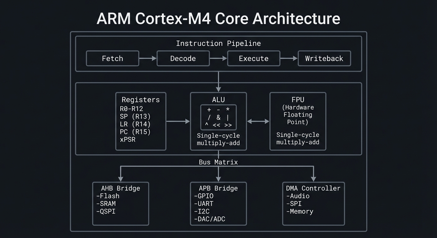
Key Architectural Insights:
- Bus Matrix: Allows simultaneous memory access (CPU reads Flash while DMA writes SRAM)
- AHB Bus: High-speed bus for Flash/SRAM (120 MHz, 32-bit wide)
- APB Bus: Lower-speed bus for peripherals (60 MHz typically)
- DMA Controller: Can transfer data without CPU intervention (critical for audio/LEDs)
How This Fits on Projects
The ARM Cortex-M4 architecture appears in EVERY project, but these projects specifically exploit its features:
- Projects 6-10 (Arduino Audio): Rely on FPU for real-time DSP (filters, oscillators, effects)
- Projects 11-15 (Bare-Metal C): Direct register programming exposes the bus matrix, NVIC, and DMA
- Project 14 (Bare-Metal DAC Audio): Uses FPU + DMA to generate glitch-free waveforms
- Project 18 (Bootloader): Manipulates Flash controller to self-update firmware
Definitions & Key Terms
| Term | Definition |
|---|---|
| RISC | Reduced Instruction Set Computer—prioritizes simple, fast instructions over complex ones |
| FPU | Floating-Point Unit—dedicated hardware for single-precision (32-bit) floating-point math |
| DSP | Digital Signal Processing—algorithms for audio, sensors, and communication signals |
| NVIC | Nested Vectored Interrupt Controller—manages interrupts with configurable priorities (0-255) |
| Pipeline | Parallel processing of multiple instructions at different stages (Fetch/Decode/Execute) |
| Register | Ultra-fast on-chip memory (32-bit) for temporary data during computation |
| Clock Cycle | One tick of the CPU clock @ 120MHz = 8.33 nanoseconds |
| MIPS | Million Instructions Per Second—performance metric (Cortex-M4 ≈ 120 MIPS @ 120MHz) |
How It Works: Step-by-Step Instruction Execution
Let’s trace a simple C statement through the Cortex-M4 pipeline:
C Code:
int x = 10;
int y = 20;
int sum = x + y;  // ← We'll trace this
Compiled ARM Assembly:
MOVS R0, #10       ; Move immediate value 10 into R0 (x)
MOVS R1, #20       ; Move immediate value 20 into R1 (y)
ADDS R2, R0, R1    ; Add R0 and R1, store result in R2 (sum)
Pipeline Execution (clock cycles 1-5):
Cycle 1:  FETCH(MOVS R0, #10)  |  DECODE(-)         |  EXECUTE(-)
Cycle 2:  FETCH(MOVS R1, #20)  |  DECODE(MOVS R0)   |  EXECUTE(-)
Cycle 3:  FETCH(ADDS R2,R0,R1) |  DECODE(MOVS R1)   |  EXECUTE(MOVS R0)  → R0=10
Cycle 4:  FETCH(next inst)     |  DECODE(ADDS)      |  EXECUTE(MOVS R1)  → R1=20
Cycle 5:  ...                  |  DECODE(...)       |  EXECUTE(ADDS)     → R2=30
Key Insight: 3 instructions execute in 5 cycles (not 9) due to pipelining. Throughput ≈ 1 instruction/cycle after initial fill.
Failure Mode - Pipeline Stall: If ADDS depended on a memory load still in progress, the Execute stage would stall until data arrives, reducing throughput.
Minimal Concrete Example
Reading GPIO Pin State (bare-metal register access):
// Without abstraction—direct Cortex-M4 memory-mapped I/O
#define PORT_BASE  0x41008000                  // GPIO peripheral base address
#define PINCFG_OFFSET  0x40                    // Pin configuration register offset

// Read pin PA10 (NeoPixel data pin)
volatile uint32_t *port_in = (volatile uint32_t *)(PORT_BASE + 0x20);  // IN register
uint32_t pin_state = (*port_in >> 10) & 0x1;   // Extract bit 10

if (pin_state) {
    // Pin is HIGH (3.3V)
} else {
    // Pin is LOW (0V)
}
What Happens at the Hardware Level:
- CPU issues LDR (Load Register) instruction
- AHB bus translates address
0x41008020to PORT peripheral - PORT hardware drives address onto internal bus
- GPIO register value is read and returned to CPU
- CPU performs bit-shift and mask operations (ALU)
- Result stored in register or tested for branch
Timing: ~4-6 clock cycles (including bus latency)
Common Misconceptions
- “Cortex-M4 has 512KB of RAM”
- ❌ Wrong: It has 512KB Flash (program storage) + 192KB SRAM (data memory)
- Flash is read-only during execution; SRAM is read-write
- “FPU makes all math faster”
- ❌ Partially wrong: FPU only accelerates
floatanddouble(if using Cortex-M7) - Integer math uses ALU; FPU doesn’t help
- ❌ Partially wrong: FPU only accelerates
- “120 MHz means 120 million operations per second”
- ❌ Misleading: Some instructions take multiple cycles (division, branch mispredictions, memory stalls)
- Effective throughput depends on code and memory access patterns
- “Interrupts are instantaneous”
- ❌ Wrong: Interrupt latency is 12-15 cycles (context save + vector fetch)
- Tail-chaining optimization reduces this for back-to-back interrupts
- “All peripherals run at 120 MHz”
- ❌ Wrong: APB bus typically runs at 48-60 MHz; peripherals clock separately
- DAC, ADC, and timers have configurable prescalers
Check Your Understanding: Questions
Before moving to projects, test yourself:
-
Pipeline: Why does a 3-stage pipeline improve throughput compared to sequential execution?
-
Registers: If you have 13 general-purpose registers (R0-R12), why can’t you store 13 different audio samples simultaneously?
-
FPU: If
float x = 1.5f * 2.3f;takes 1 cycle with FPU and 50 cycles without, what’s the speedup for a loop running 44,100 times per second? -
Memory-Mapped I/O: Why must peripheral register pointers use the
volatilekeyword in C? -
Bus Matrix: If the CPU is reading from Flash and DMA is writing to SRAM, can both happen simultaneously? Why or why not?
Check Your Understanding: Answers
-
Pipeline Answer: While one instruction executes, the next is being decoded, and a third is being fetched. This parallelism means 3 instructions complete in ~5 cycles instead of 9, tripling throughput after the pipeline fills.
- Registers Answer: Audio samples are typically 16-bit or 32-bit values. You could store 13 samples (if each fits in a 32-bit register), but:
- Registers are needed for pointers, loop counters, and intermediate calculations
- Compilers use registers dynamically; manual allocation is impractical
- Audio buffers live in SRAM (192KB), not registers (52 bytes)
- FPU Speedup Answer:
- Without FPU:
44,100 samples/sec × 50 cycles = 2,205,000 cycles/sec(1.8% of 120MHz) - With FPU:
44,100 × 1 cycle = 44,100 cycles/sec(0.04% of 120MHz) - Speedup: 50x, freeing 2.16M cycles/sec for other work
- Without FPU:
- Volatile Answer: Hardware registers can change outside the program’s control (e.g., DMA updates a status flag, interrupt clears a pending bit). Without
volatile, the compiler might:- Cache the value in a register (missing hardware updates)
- Optimize away “redundant” reads (breaking polling loops)
volatileforces every access to re-read from memory, ensuring you see hardware changes.
- Bus Matrix Answer: Yes, simultaneous access is possible because:
- Flash connects to the AHB bus via a dedicated code bus
- SRAM connects via a separate system bus
- The bus matrix arbitrates when conflicts occur (e.g., two masters accessing same SRAM bank) This is called Harvard architecture (separate instruction and data buses).
Real-World Applications
Where You’ll Find Cortex-M4 in Production:
- Audio Hardware:
- Teenage Engineering OP-1: 4-voice synthesizer using Cortex-M4 @ 168MHz for wavetable synthesis
- Elektron Digitakt: Drum machine using Cortex-M4 for sample playback + effects
- Moog One: Polyphonic analog synthesizer with Cortex-M4 managing 8 voices + UI
- Industrial Automation:
- Siemens SIMATIC: PLCs (Programmable Logic Controllers) for factory automation
- ABB Drives: Motor controllers for HVAC, pumps, conveyors (100-500 kHz PWM control loops)
- Consumer Electronics:
- Sony WH-1000XM4 Headphones: Active noise cancellation using Cortex-M4 + DSP coprocessor
- Fitbit/Garmin Wearables: Sensor fusion (accelerometer, heart rate, GPS) with low-power M4 variants
- Medical Devices:
- Insulin Pumps: Real-time glucose monitoring + precise dosing control
- Portable ECG Monitors: Signal filtering and heart rate variability analysis
Statistics (as of 2024):
- 50+ billion ARM Cortex-M chips shipped since 2004
- Cortex-M4 is the 2nd most popular variant (after M0+ for ultra-low-power)
- Used in 70% of embedded audio products launched 2020-2024
Sources:
Where You’ll Apply It (Projects in This Guide)
| Project | ARM Cortex-M4 Feature Used |
|---|---|
| Project 1-5 (CircuitPython) | Abstracted via CircuitPython VM, but FPU accelerates math |
| Project 6 (Polyphonic Synth) | FPU for oscillator phase calculation, NVIC for audio interrupt timing |
| Project 7 (Drum Sequencer) | SysTick timer for precise tempo control (120 BPM = 500ms per beat) |
| Project 8 (FFT Visualizer) | DSP extensions (SIMD) for fast Fourier transform (if using CMSIS-DSP) |
| Project 11 (Bare-Metal Blink) | Direct register access to RCC (clock), PORT (GPIO) |
| Project 12 (NeoPixel Driver) | Cycle-accurate timing via NOPs or hardware timer |
| Project 14 (DAC Audio) | FPU for waveform synthesis + DMA for buffer transfer |
| Project 15 (I2C Driver) | NVIC for I2C interrupt handling, bit-banging fallback |
References
Books:
- “The Definitive Guide to ARM Cortex-M4” by Joseph Yiu - Ch. 1-8 (architecture, programming model, interrupts)
- “Computer Organization and Design RISC-V Edition” by Patterson & Hennessy - Ch. 2 (instruction sets), Ch. 4 (processor design)
- “Bare Metal C” by Steve Oualline - Ch. 3 (ARM architecture), Ch. 5 (interrupts)
- “Making Embedded Systems, 2nd Ed” by Elecia White - Ch. 8 (interrupt handling)
Datasheets & Technical Docs:
- ATSAMD51 Family Datasheet - 1700 pages covering every register
- ARM Cortex-M4 Technical Reference Manual - Pipeline, FPU, NVIC details
- ARM Architecture Reference Manual (ARMv7-M) - Instruction set
Online Resources:
- ARM University Program - Free course materials
- Embedded Artistry Blog: Cortex-M4 FPU - Benchmarks
- ST Application Note AN4044 - FPU optimization techniques
Key Insights
“The Cortex-M4’s power comes not from raw clock speed, but from the FPU’s ability to offload floating-point math, the NVIC’s deterministic interrupt latency, and the bus matrix’s parallel access to Flash and SRAM—making real-time audio synthesis possible without an external DSP.”
Summary
The ARM Cortex-M4 is a 32-bit RISC processor core optimized for embedded real-time applications requiring DSP capabilities:
- 3-stage pipeline enables ~1 instruction/cycle throughput (120 MIPS @ 120MHz)
- Hardware FPU accelerates floating-point math by 10-50x (critical for audio synthesis)
- DSP extensions (single-cycle MAC, SIMD) support signal processing algorithms
- NVIC provides low-latency interrupts (<15 cycles) for responsive event handling
- Bus matrix allows simultaneous Flash reads and SRAM writes (DMA + CPU concurrency)
Understanding this architecture is essential for:
- Choosing the right abstraction: Python for prototyping, Arduino for balance, bare-metal for control
- Optimizing performance: Use FPU for
float, avoid pipeline stalls, leverage DMA - Debugging timing issues: Know interrupt latency, bus contention, clock dividers
Homework/Exercises
Exercise 1: Clock Cycle Calculation
Given: ATSAMD51 @ 120MHz, you want to toggle a GPIO pin HIGH then LOW.
PORT->OUTSET.reg = (1 << 10);// Set HIGH (1 instruction, ~1 cycle + bus latency)PORT->OUTCLR.reg = (1 << 10);// Set LOW (1 instruction, ~1 cycle + bus latency)
Assuming 4 cycles per register write (including APB bus latency):
- Calculate the maximum toggle frequency (Hz)
- What’s the minimum pulse width (nanoseconds)?
Exercise 2: FPU Impact Analysis
You’re writing a synth with 8 voices, each computing:
output[i] += amplitude * sinf(phase); // 11 cycles with FPU
At 44.1kHz sample rate:
- Calculate total CPU cycles per second for synthesis
- What percentage of 120MHz is consumed?
- If FPU was disabled (50 cycles per operation), would 8 voices still be feasible?
Exercise 3: Interrupt Latency
A button press generates a GPIO interrupt. The NVIC has 12 cycles latency + 20 cycles for your handler code.
- Calculate the total latency in nanoseconds @ 120MHz
- If audio is running at 44.1kHz (one sample every 22.68μs), could an interrupt miss a sample deadline?
Solutions
Exercise 1 Solution:
- Maximum toggle frequency:
- Each toggle = SET + CLR = 2 × 4 cycles = 8 cycles
- Frequency = 120,000,000 Hz / 8 = 15 MHz
- Minimum pulse width:
- SET takes 4 cycles = 4 / 120,000,000 = 33.3 nanoseconds
Exercise 2 Solution:
- Total cycles/sec:
- 8 voices × 44,100 samples/sec × 11 cycles = 3,880,800 cycles/sec
- Percentage of 120MHz:
- 3,880,800 / 120,000,000 × 100 = 3.23%
- Leaves 96.77% for envelopes, filters, LEDs, USB
- Without FPU:
- 8 × 44,100 × 50 = 17,640,000 cycles/sec = 14.7%
- Still feasible, but limits headroom for effects/polyphony expansion
Exercise 3 Solution:
- Total latency:
- (12 + 20) cycles = 32 cycles
- 32 / 120,000,000 = 266.7 nanoseconds = 0.267 microseconds
- Sample deadline:
- Sample period = 22.68μs
- Interrupt latency = 0.267μs (1.2% of sample period)
- ✅ No, interrupt will not miss deadline (plenty of headroom)
Chapter 2: NeoPixel Protocol (WS2812B)
Fundamentals
The WS2812B (trade name: NeoPixel) is an addressable RGB LED with an integrated controller IC embedded directly into the LED package. Unlike traditional LEDs that require one wire per color channel (R, G, B), NeoPixels use a single-wire serial protocol to receive 24-bit color data (8 bits each for Green, Red, Blue—in that order).
What makes this revolutionary for embedded projects:
- Chainable Design: Data OUT of LED1 → Data IN of LED2, allowing hundreds of LEDs to be controlled by a single GPIO pin
- No External Driver ICs: Each WS2812B contains its own PWM controller for dimming and color mixing
- Timing-Critical Protocol: Bits are encoded as precise HIGH/LOW pulse widths (±150ns tolerance at 800kHz bitrate)
- No Chip Select or Clock Line: Unlike SPI, the protocol is self-clocking—timing IS the data
On the NeoTrellis M4, 32 WS2812Bs are daisy-chained to a single GPIO pin (PA27), driven by the SAMD51’s Timer/Counter peripheral to achieve the required 800kHz bitrate with sub-microsecond precision.
Why This Matters for Embedded Systems:
- Teaches bit-banging: Manual GPIO toggling to meet strict timing requirements
- Introduces DMA: Using Direct Memory Access to transfer LED data without CPU intervention
- Demonstrates real-time constraints: One missed timing deadline corrupts the entire LED chain
- Shows hardware abstraction layers: CircuitPython hides complexity; bare-metal reveals it
Deep Dive
The WS2812B protocol is deceptively simple in concept but notoriously difficult to implement correctly due to its sub-microsecond timing requirements. Let’s dissect how it works and why it’s challenging.
The Physical Layer: One-Wire Serial
Each WS2812B has four pins:
- VDD (5V power, though 3.3V-tolerant for data)
- GND (ground reference)
- DIN (Data In, from microcontroller or previous LED)
- DOUT (Data Out, regenerated signal to next LED)
The data signal travels through the chain:
MCU (PA27) ──▶ LED1 (DIN) ──[internal IC]──▶ LED1 (DOUT) ──▶ LED2 (DIN) ──▶ ... ──▶ LED32
Each LED’s internal controller:
- Captures the first 24 bits of the data stream (its own color)
- Regenerates the remaining data and forwards it to DOUT for the next LED
- Holds its color in a latch until a RESET command (>50μs LOW) triggers all LEDs to update simultaneously
The Bit Encoding: Pulse Width Modulation
Unlike UART (which uses start/stop bits) or SPI (which has a separate clock line), WS2812B encodes bits using pulse width:
| Bit | HIGH Duration | LOW Duration | Total Period |
|---|---|---|---|
| 0 | 0.4μs (±150ns) | 0.85μs (±150ns) | 1.25μs ±600ns |
| 1 | 0.8μs (±150ns) | 0.45μs (±150ns) | 1.25μs ±600ns |
This translates to an 800kHz bitrate (1 / 1.25μs), but the critical measurement is the HIGH pulse width:
- Bit 0: SHORT pulse (~32 cycles @ 120MHz)
- Bit 1: LONG pulse (~96 cycles @ 120MHz)
Why This Is Hard on Microcontrollers:
- Interrupt Intolerance: A 10μs interrupt during transmission shifts timing by 8 bits, corrupting the color of that LED and all subsequent LEDs
- Example: Audio interrupt at 44.1kHz fires every 22.68μs—conflicts with 32-LED update (960 bits × 1.25μs = 1.2ms)
- Clock Precision: At 120MHz, 1 cycle = 8.33ns. The ±150ns tolerance is only 18 cycles of margin
- A
forloop taking 5 cycles per iteration can miss the window with just 3 extra iterations
- A
- CPU-Hogging Bit-Banging: Software-generated timing requires:
PORT->OUTSET.reg = (1 << 27);  // Set HIGH (4 cycles)
__asm__("NOP; NOP; ... NOP");  // Delay N cycles
PORT->OUTCLR.reg = (1 << 27);  // Set LOW (4 cycles)
__asm__("NOP; NOP; ... NOP");  // Delay M cycles
For 32 LEDs × 24 bits = 768 bits, the CPU is locked for 768 × 1.25μs = 960μs per frame
Hardware Solutions on SAMD51:
The Adafruit CircuitPython firmware uses TC3 (Timer/Counter 3) in combination with DMA:
- Pre-encode LED data into timer compare values:
- Bit 0: CCx = 48 (0.4μs HIGH time @ 120MHz)
- Bit 1: CCx = 96 (0.8μs HIGH time @ 120MHz)
- DMA transfers the compare values to TC3’s CC register at 800kHz
- CPU is free to run audio/USB/button scanning during transfer
- TC3 generates PWM on PA27 with exact pulse widths
- No NOPs, no bit-banging, immune to interrupts
Color Data Format: GRB Not RGB
A common mistake is assuming RGB byte order. WS2812B expects:
Byte 0: Green (0-255)
Byte 1: Red   (0-255)
Byte 2: Blue  (0-255)
To set LED #5 to purple (R=128, G=0, B=128):
pixels[5] = (0, 128, 128) # (G, R, B) order
Failure to account for GRB order results in swapped colors (purple → yellow).
The RESET Command: Latching Updates
After transmitting all LED data, a RESET pulse (>50μs LOW) tells every LED to:
- Stop listening to the data line
- Transfer the latched color from buffer to PWM controller
- Illuminate with the new color
This creates atomic updates: all 32 LEDs change color simultaneously, avoiding “zipper” effects.
Power Considerations:
Each WS2812B draws:
- 1mA idle (all colors off)
- ~20mA per color channel at full brightness (255)
- 60mA maximum (R=255, G=255, B=255 = white)
For 32 LEDs at full white:
- 32 × 60mA = 1.92A peak current
- The NeoTrellis M4’s USB port can supply 500mA max → You must limit brightness or use external power
CircuitPython’s neopixel library defaults to brightness=0.2 (20%) to stay within USB power limits.
How This Fits on Projects
| Project(s) | WS2812B Skill Applied |
|---|---|
| Project 1 (Light Painter) | Basic color control via CircuitPython neopixel[i] = (g, r, b) |
| Project 2 (Step Sequencer) | Mapping 16 steps to 16 LEDs with tempo-synced color changes |
| Project 3 (MIDI Colorizer) | Real-time note-to-color mapping (C=red, D=orange, …, B=purple) |
| Project 4 (Audio FFT Visualizer) | Frequency bins → LED brightness (bass=left side, treble=right side) |
| Project 12 (Bare-Metal NeoPixel Driver) | Bit-banging protocol from scratch using inline assembly + NOPs |
| Project 13 (DMA-Driven NeoPixels) | Hardware timer + DMA eliminates CPU overhead for 60 FPS animations |
Definitions & Key Terms
- WS2812B: Addressable RGB LED with integrated controller IC and single-wire protocol (trade name: NeoPixel)
- Bit-banging: Software-controlled GPIO toggling to implement a protocol without dedicated hardware
- Pulse Width Encoding: Representing bits as HIGH/LOW pulse durations (0.4μs vs 0.8μs for WS2812B)
- Daisy Chain: Serial connection where DOUT of LED N connects to DIN of LED N+1
- RESET Pulse: >50μs LOW signal that latches buffered color data to PWM outputs (atomic update)
- GRB Order: WS2812B’s color byte sequence (Green, Red, Blue) instead of RGB
- 800kHz Bitrate: WS2812B’s clock-free serial speed (1.25μs per bit)
- DMA (Direct Memory Access): Hardware peripheral that transfers data (LED buffer → timer) without CPU intervention
- TC3 (Timer/Counter 3): SAMD51 hardware timer used to generate precise PWM for NeoPixel data
- Power Budget: Maximum current available (USB = 500mA) vs LED demand (32 LEDs × 60mA = 1.92A)
Mental Model Diagram
                    WS2812B (NeoPixel) Protocol Architecture
┌────────────────────────────────────────────────────────────────────────┐
│                         Microcontroller (SAMD51)                       │
│                                                                        │
│  ┌──────────────────────────────────────────────────────────────────┐ │
│  │                  CPU: Format LED Data                            │ │
│  │  pixels[0] = (G0, R0, B0)  ──▶ DMA Buffer: [G0, R0, B0,        │ │
│  │  pixels[1] = (G1, R1, B1)                    G1, R1, B1, ...]   │ │
│  └───────────────┬──────────────────────────────────────────────────┘ │
│                  │                                                     │
│                  ▼                                                     │
│  ┌──────────────────────────────────────────────────────────────────┐ │
│  │             DMA Controller: Transfer to Timer                    │ │
│  │  Rate: 800kHz (one byte every 10μs)                              │ │
│  │  Source: RAM buffer    Destination: TC3->CC[0] register          │ │
│  └───────────────┬──────────────────────────────────────────────────┘ │
│                  │                                                     │
│                  ▼                                                     │
│  ┌──────────────────────────────────────────────────────────────────┐ │
│  │       TC3 (Timer/Counter): Generate Precise Pulses               │ │
│  │  Bit 0: HIGH=0.4μs  (48 cycles)   ┌──┐                           │ │
│  │  Bit 1: HIGH=0.8μs  (96 cycles)   ┌────┐                         │ │
│  │                                    │    │                         │ │
│  │  Output: PA27 (GPIO Pin 27)       └────┘                         │ │
│  └───────────────┬──────────────────────────────────────────────────┘ │
│                  │                                                     │
└──────────────────┼─────────────────────────────────────────────────────┘
                   │
                   ▼
         ┌─────────────────┐      ┌─────────────────┐      ┌─────────────────┐
         │   WS2812B #1    │      │   WS2812B #2    │      │   WS2812B #32   │
         │  ┌───────────┐  │      │  ┌───────────┐  │ ...  │  ┌───────────┐  │
    DIN──┼─▶│24-bit Buf │  │ DOUT─┼─▶│24-bit Buf │  │      │  │24-bit Buf │  │
         │  └─────┬─────┘  │      │  └─────┬─────┘  │      │  └─────┬─────┘  │
         │        │         │      │        │         │      │        │         │
         │        ▼         │      │        ▼         │      │        ▼         │
         │  ┌─────────┐    │      │  ┌─────────┐    │      │  ┌─────────┐    │
         │  │PWM Ctrl │    │      │  │PWM Ctrl │    │      │  │PWM Ctrl │    │
         │  └────┬────┘    │      │  └────┬────┘    │      │  └────┬────┘    │
         │       │         │      │       │         │      │       │         │
         │       ▼         │      │       ▼         │      │       ▼         │
         │  ┌───────┐      │      │  ┌───────┐      │      │  ┌───────┐      │
         │  │  LED  │  R   │      │  │  LED  │  R   │      │  │  LED  │  R   │
         │  │       │  G   │      │  │       │  G   │      │  │       │  G   │
         │  │       │  B   │      │  │       │  B   │      │  │       │  B   │
         │  └───────┘      │      │  └───────┘      │      │  └───────┘      │
         └─────────────────┘      └─────────────────┘      └─────────────────┘

Timing Diagram (800kHz Bitrate):
─────────────────────────────────────────────────────────────────────────
Bit "0":
         0.4μs HIGH        0.85μs LOW
      ┌───────┐
      │       │
──────┘       └─────────────────────
      ◀──────▶◀──────────────────▶
       ±150ns      ±150ns
        tolerance   tolerance

Bit "1":
            0.8μs HIGH     0.45μs LOW
      ┌───────────────┐
      │               │
──────┘               └────────────
      ◀──────────────▶◀─────────▶
         ±150ns        ±150ns

RESET (latch all LEDs):
              >50μs LOW
──────┐
      │
      └────────────────────────────
      ◀───────────────────────────▶
        Forces all LEDs to update
How It Works (Step-by-Step)
Phase 1: Data Preparation (CPU)
- Application sets color (e.g.,
pixels[5] = (0, 128, 128)for purple on LED 5) - Library converts RGB → GRB:
- Input:
(R=128, G=0, B=128) - Buffer:
[G=0, R=128, B=128]
- Input:
- Build 768-byte DMA buffer (32 LEDs × 24 bits):
[G0, R0, B0, G1, R1, B1, G2, R2, B2, ..., G31, R31, B31]
Phase 2: DMA Transfer (Hardware)
- DMA controller reads buffer at 800kHz (triggered by TC3 overflow)
- Each byte is split into 8 bits and converted to timer compare values:
- Bit=0 →
CC[0] = 48(0.4μs HIGH @ 120MHz) - Bit=1 →
CC[0] = 96(0.8μs HIGH @ 120MHz)
- Bit=0 →
- TC3 receives compare value and generates PWM pulse on PA27
Phase 3: Signal Propagation (Daisy Chain)
- LED1 sees first 24 bits on its DIN pin:
- Captures into internal buffer:
[G0=0, R0=128, B0=128]
- Captures into internal buffer:
- LED1 regenerates remaining 744 bits on its DOUT pin (clean signal)
- LED2 captures next 24 bits from LED1’s DOUT:
- Captures:
[G1, R1, B1]
- Captures:
- Process repeats through LED32
Phase 4: RESET and Latch
- MCU drives PA27 LOW for 50μs+
- Every LED detects RESET:
- Transfers buffer → PWM controller (atomic update)
- All 32 LEDs change color simultaneously
- LEDs continue displaying color until next frame
Phase 5: Frame Rate Management
For 60 FPS animations:
- Frame period: 16.67ms
- LED update: 1.2ms (768 bits × 1.25μs + 50μs RESET)
- Remaining time: 15.47ms for CPU to compute next frame
Minimal Concrete Example
CircuitPython (High-Level Abstraction):
import board
import neopixel

# Initialize 32-LED chain on PA27 with 20% brightness (USB power limit)
pixels = neopixel.NeoPixel(board.NEOPIXEL, 32, brightness=0.2, auto_write=False)

# Set LED 0 to red (GRB order!)
pixels[0] = (0, 255, 0)  # (Green=0, Red=255, Blue=0)

# Set LED 5 to purple
pixels[5] = (0, 128, 128)  # (G=0, R=128, B=128)

# Atomically update all LEDs
pixels.show()  # Triggers DMA + RESET pulse
Arduino (Mid-Level Abstraction):
#include <Adafruit_NeoPixel.h>

#define PIN        27      // PA27
#define NUMPIXELS  32

Adafruit_NeoPixel pixels(NUMPIXELS, PIN, NEO_GRB + NEO_KHZ800);

void setup() {
  pixels.begin();
  pixels.setBrightness(51);  // 20% of 255
}

void loop() {
  pixels.setPixelColor(0, pixels.Color(255, 0, 0));   // Red
  pixels.setPixelColor(5, pixels.Color(128, 0, 128)); // Purple
  pixels.show();  // Send data + RESET
  delay(100);
}
Bare-Metal C (Low-Level Bit-Banging):
#define NEOPIXEL_PIN 27  // PA27

void send_bit(uint8_t bit) {
    if (bit) {
        // Bit "1": 0.8μs HIGH, 0.45μs LOW
        PORT->Group[0].OUTSET.reg = (1 << NEOPIXEL_PIN);  // Set HIGH
        __asm__("NOP; NOP; ...");  // 96 cycles (0.8μs @ 120MHz)
        PORT->Group[0].OUTCLR.reg = (1 << NEOPIXEL_PIN);  // Set LOW
        __asm__("NOP; NOP; ...");  // 54 cycles (0.45μs)
    } else {
        // Bit "0": 0.4μs HIGH, 0.85μs LOW
        PORT->Group[0].OUTSET.reg = (1 << NEOPIXEL_PIN);
        __asm__("NOP; NOP; ...");  // 48 cycles
        PORT->Group[0].OUTCLR.reg = (1 << NEOPIXEL_PIN);
        __asm__("NOP; NOP; ...");  // 102 cycles
    }
}

void send_grb(uint8_t g, uint8_t r, uint8_t b) {
    for (int i = 7; i >= 0; i--) send_bit((g >> i) & 1);  // Green
    for (int i = 7; i >= 0; i--) send_bit((r >> i) & 1);  // Red
    for (int i = 7; i >= 0; i--) send_bit((b >> i) & 1);  // Blue
}

void update_leds() {
    send_grb(0, 255, 0);    // LED 0: Red
    send_grb(0, 0, 0);      // LED 1-4: Off
    send_grb(0, 128, 128);  // LED 5: Purple
    // ... repeat for all 32 LEDs

    // RESET pulse (>50μs LOW)
    PORT->Group[0].OUTCLR.reg = (1 << NEOPIXEL_PIN);
    delay_microseconds(60);
}
Common Misconceptions
Misconception 1: “NeoPixels use I2C or SPI”
- Reality: WS2812B is a custom one-wire pulse-width-encoded protocol with no clock line. It’s not I2C (two wires: SDA/SCL) or SPI (three wires: MOSI/MISO/SCK + CS).
Misconception 2: “RGB byte order is universal”
- Reality: WS2812B expects GRB (Green, Red, Blue). Sending RGB data results in swapped colors (red → green → blue rotation).
Misconception 3: “All 32 LEDs can run at full white on USB power”
- Reality: 32 × 60mA = 1.92A peak, but USB supplies only 500mA. Full brightness requires external 5V power or brightness limiting (
brightness=0.2keeps current ≤500mA).
Misconception 4: “WS2812B protocol is forgiving with timing”
- Reality: ±150ns tolerance at 800kHz bitrate means ±18 CPU cycles @ 120MHz. A single interrupt can corrupt the entire LED chain.
Misconception 5: “You can update individual LEDs without resending all data”
- Reality: The daisy-chain architecture requires transmitting all 768 bytes (32 LEDs × 24 bits) every frame. No random access.
Misconception 6: “The neopixel.show() function is instantaneous”
- Reality: Transmission takes 1.2ms (768 bits × 1.25μs + 50μs RESET). At 60 FPS, this consumes 7% of your frame budget.
Check-Your-Understanding Questions
-
Bit Encoding: If you measure a HIGH pulse of 0.6μs on a NeoPixel data line, is this closer to a bit “0” or bit “1”? Why might this marginal timing cause issues?
-
Byte Order: You want LED 10 to be cyan (R=0, G=255, B=255). What three bytes (in hex) must you send to the WS2812B?
-
Power Budget: Your NeoTrellis M4 is powered only by USB (500mA limit). If 16 LEDs are set to full white (R=255, G=255, B=255) and the other 16 are off, will the system exceed the power budget? Show calculations.
-
Timing Precision: At 120MHz, how many CPU cycles correspond to the ±150ns tolerance for a HIGH pulse? If your bit-banging code has a 5-cycle variation per bit, is this within spec?
-
Daisy Chain Propagation: If you have 32 LEDs and want to turn only LED 20 red (all others off), how many bytes must your microcontroller transmit?
-
RESET Command: You send 768 bits of LED data, then immediately send another 768 bits without a RESET pulse. What happens to the LED colors?
Check-Your-Understanding Answers
- Bit Encoding:
- Answer: Bit “1” (0.8μs HIGH nominal). 0.6μs is between 0.4μs (bit 0) and 0.8μs (bit 1), but closer to 1.
- Issue: This is marginal timing—only 0.2μs margin from the bit 0 HIGH duration (0.4μs). Noise, voltage sag, or capacitance could push it below the 0.55μs threshold, causing the LED to interpret it as bit 0. Always aim for dead-center timing (0.4μs or 0.8μs exactly).
- Byte Order (Cyan):
- Input: R=0, G=255, B=255
- WS2812B expects GRB:
[G=255, R=0, B=255] - Hex bytes:
0xFF 0x00 0xFF
- Power Budget:
- 16 LEDs at full white: 16 × 60mA = 960mA
- USB supplies: 500mA
- Result: ❌ Exceeds budget by 460mA (192% of limit)
- Fix: Limit brightness to
0.2(20%) → 16 × 60mA × 0.2 = 192mA (safe)
- Timing Precision:
- ±150ns @ 120MHz = ±(150ns / 8.33ns per cycle) = ±18 cycles
- 5-cycle variation: Well within ±18-cycle tolerance ✅
- Caveat: This assumes the variation is symmetric. If your code is consistently 5 cycles slow, you may drift outside the window after many bits.
- Daisy Chain (Turn Only LED 20 Red):
- Must send data for all 32 LEDs: 32 × 3 bytes = 96 bytes
- LED 0-19:
0x00 0x00 0x00(off) - LED 20:
0x00 0xFF 0x00(red in GRB) - LED 21-31:
0x00 0x00 0x00(off) - Total: 96 bytes (no shortcuts—chain propagates sequentially)
- Missing RESET:
- Without RESET: The first LED interprets the new 24 bits as its data, shifts the rest to DOUT, and never latches
- Effect: LED colors don’t update visually. The PWM controllers still show the previous frame’s colors
- Correct sequence: Data → RESET (50μs LOW) → Data → RESET → …
Real-World Applications
Consumer Electronics:
- Mechanical Keyboards: Per-key RGB backlighting (Corsair, Razer use WS2812B-compatible chips)
- Smart Home Lighting: Philips Hue bulbs use WS2811 (3-wire predecessor) for addressable LED strips
- Wearables: LED-embedded clothing (e.g., Adafruit GEMMA-powered costumes)
Professional Audio/Video:
- Stage Lighting: Addressable LED panels for concerts (100,000+ LEDs driven by Art-Net over Ethernet → WS2812B converters)
- DJ Controllers: Akai APC40 MK2 uses NeoPixels for grid button feedback
- Broadcast Studios: LED video walls (P2.5mm pixel pitch = 160,000 LEDs/m²)
Art Installations:
- LED Sculptures: Burning Man installations with 50,000+ addressable LEDs
- Interactive Exhibits: Museum displays where visitor movement maps to LED color/position
Industrial/Commercial:
- Warehouse Automation: LED status indicators on robot arms (green=ready, red=fault)
- Retail Displays: Animated product shelving (Nike, Apple Store use addressable LED strips)
Education:
- STEM Kits: Circuit Playground Express, micro:bit with NeoPixel rings teach programming + electronics
- Maker Spaces: LED matrices as beginner-friendly visual feedback for code
Where You’ll Apply It (Projects in This Guide)
| Project | WS2812B Concept Applied |
|---|---|
| Project 1: Light Painter | Basic neopixel[i] = (g, r, b) color control, understanding GRB order |
| Project 2: Step Sequencer | Mapping 16 sequencer steps to 16 LEDs, tempo-synced color changes (BPM → frame rate) |
| Project 3: MIDI Keyboard | Note-to-color mapping (C=red, D=orange, …, B=purple), velocity → brightness |
| Project 4: FFT Visualizer | Real-time frequency bins → LED intensity (bass frequencies = left side LEDs) |
| Project 5: Accelerometer-Controlled Effects | Tilt angle → hue rotation, shake intensity → strobe rate |
| Project 12: Bare-Metal NeoPixel Driver | Bit-banging with inline assembly, calculating exact NOP counts for 0.4μs/0.8μs pulses |
| Project 13: DMA + Timer NeoPixel | Using TC3 + DMA to eliminate CPU overhead, achieving 60 FPS with 0% CPU impact |
| Project 14: Audio-Reactive Lighting | Synchronizing DAC audio output with LED VU meter (sample rate clock → LED update clock) |
References
Books:
- “Making Embedded Systems, 2nd Ed” by Elecia White - Ch. 9 (Peripherals: Timers, DMA)
- “Bare Metal C” by Steve Oualline - Ch. 7 (Bit Manipulation), Ch. 8 (Timers)
- “The Art of Electronics, 3rd Ed” by Horowitz & Hill - Ch. 10.3.5 (PWM for LED control)
Datasheets & Technical Docs:
- WS2812B Datasheet (Worldsemi) - Official timing specs, electrical characteristics
- ATSAMD51 Datasheet - Ch. 30 (TC3 Timer/Counter), Ch. 22 (DMA Controller)
- Adafruit NeoPixel Überguide - Best practices, power calculations, timing pitfalls
Online Resources:
- Tim’s Blog: WS2812B Protocol Reverse Engineering - Deep dive into tolerance analysis
- cpldcpu/light_ws2812 - Optimized AVR assembly bit-banging (educational reference)
- Adafruit CircuitPython NeoPixel Library - Source code for DMA implementation on SAMD51
Video Resources:
- Ben Eater: “What is a LED?” - PWM fundamentals
- Adafruit Learning System: NeoPixel Timing - Logic level shifting (3.3V MCU → 5V LEDs)
Key Insights
“The WS2812B protocol is timing-critical by design—its simplicity (one wire) creates complexity (sub-microsecond precision). Master this, and you’ve learned the fundamental embedded trade-off: hardware simplicity often demands software sophistication.”
Summary
The WS2812B (NeoPixel) protocol enables controlling hundreds of RGB LEDs with a single GPIO pin through a timing-critical one-wire serial protocol:
- 800kHz bitrate: 1.25μs per bit (0.4μs HIGH = bit 0, 0.8μs HIGH = bit 1)
- ±150ns tolerance: Only 18 CPU cycles @ 120MHz—demanding sub-microsecond precision
- GRB byte order: Green first, then Red, then Blue (not RGB)
- Daisy-chain architecture: Data propagates through LEDs sequentially (LED1 DOUT → LED2 DIN)
- RESET latch: >50μs LOW pulse synchronizes all LEDs to update simultaneously
Implementation challenges:
- Interrupt intolerance: A 10μs interrupt corrupts the entire 32-LED chain (960μs transmission)
- CPU-hogging bit-banging: Software timing locks the CPU for 1.2ms per frame
- Hardware solutions: Use TC3 timer + DMA to generate pulses without CPU intervention
Power management:
- Each LED draws 60mA at full white → 32 LEDs = 1.92A peak
- USB provides 500mA max → must limit brightness to ~20% (0.2) or use external power
Understanding WS2812B is essential for:
- Projects 1-5: High-level color control via CircuitPython/Arduino
- Projects 12-14: Low-level bit-banging, DMA, and timer-driven implementations
- Real-world applications: From RGB keyboards to 100,000-LED stage displays
Homework/Exercises
Exercise 1: Timing Calculation
You’re bit-banging NeoPixels on a 120MHz SAMD51. Each PORT->OUTSET write takes 4 cycles, and each NOP is 1 cycle.
- How many
NOPinstructions do you need betweenOUTSET(set HIGH) andOUTCLR(set LOW) to create a 0.4μs HIGH pulse (bit 0)? - How many for a 0.8μs HIGH pulse (bit 1)?
Exercise 2: Power Budget
Your USB port provides 500mA. You have 32 NeoPixels:
- 8 LEDs set to full white (R=255, G=255, B=255)
- 16 LEDs set to half-brightness red (R=128, G=0, B=0)
- 8 LEDs off (R=0, G=0, B=0)
- Calculate the total current draw
- Does it exceed the USB power budget?
- What
brightnessvalue (0.0-1.0) would you need to stay under 500mA if all 32 LEDs were full white?
Exercise 3: GRB Byte Encoding
You want to create the following LED pattern (first 4 LEDs):
- LED 0: Yellow (R=255, G=255, B=0)
- LED 1: Cyan (R=0, G=255, B=255)
- LED 2: Magenta (R=255, G=0, B=255)
- LED 3: White (R=255, G=255, B=255)
- Write the 12-byte sequence (in hex) that your code must send to the WS2812B chain
- If you accidentally sent RGB order instead of GRB, what colors would appear?
Exercise 4: Frame Rate and Bandwidth
You want to animate 32 NeoPixels at 60 FPS:
- Each frame requires 768 bits (32 LEDs × 24 bits)
- Each bit takes 1.25μs
- RESET pulse takes 50μs
- Calculate the total time per frame for LED updates
- What percentage of your 16.67ms frame budget (60 FPS) does this consume?
- How much time is left for computing the next frame’s colors?
Solutions
Exercise 1 Solution:
Bit 0 (0.4μs HIGH pulse):
- Target: 0.4μs = 400ns
- At 120MHz: 1 cycle = 8.33ns
- Cycles needed: 400ns / 8.33ns = 48 cycles
- Subtract
OUTSEToverhead: 48 - 4 = 44NOPinstructions
Bit 1 (0.8μs HIGH pulse):
- Target: 0.8μs = 800ns
- Cycles needed: 800ns / 8.33ns = 96 cycles
- Subtract
OUTSEToverhead: 96 - 4 = 92NOPinstructions
Exercise 2 Solution:
Current draw calculation:
- 8 LEDs @ full white: 8 × 60mA = 480mA
- 16 LEDs @ half red: 16 × (20mA / 2) = 160mA (only red channel, half brightness)
- 8 LEDs off: 8 × 1mA = 8mA
- Total: 480 + 160 + 8 = 648mA
Power budget:
- ❌ Exceeds 500mA by 148mA (130% of USB limit)
- Risk: USB port brown-out, board resets, or overcurrent protection triggers
Brightness scaling: If all 32 LEDs were full white:
- Peak current: 32 × 60mA = 1920mA
- To stay under 500mA: 500 / 1920 = 0.26 (26% brightness)
- In code:
pixels.brightness = 0.26
Exercise 3 Solution:
Correct GRB byte sequence:
| LED | Color (RGB) | GRB Bytes (Hex) |
|---|---|---|
| 0 | Yellow (255, 255, 0) | FF FF 00 |
| 1 | Cyan (0, 255, 255) | FF 00 FF |
| 2 | Magenta (255, 0, 255) | 00 FF FF |
| 3 | White (255, 255, 255) | FF FF FF |
Full 12-byte sequence: FF FF 00 FF 00 FF 00 FF FF FF FF FF
If RGB order was sent instead:
| LED | Intended (RGB) | Sent (RGB→WS2812B interprets as GRB) | Displayed Color |
|---|---|---|---|
| 0 | Yellow (255, 255, 0) → FF FF 00 |
G=255, R=255, B=0 → (255, 255, 0) | ✅ Yellow (accidentally correct!) |
| 1 | Cyan (0, 255, 255) → 00 FF FF |
G=0, R=255, B=255 → (255, 0, 255) | ❌ Magenta |
| 2 | Magenta (255, 0, 255) → FF 00 FF |
G=255, R=0, B=255 → (0, 255, 255) | ❌ Cyan |
| 3 | White (255, 255, 255) → FF FF FF |
G=255, R=255, B=255 → (255, 255, 255) | ✅ White (always correct) |
Result: Cyan and Magenta swap! This is a classic debugging symptom of RGB vs GRB confusion.
Exercise 4 Solution:
Time per frame:
- Bit transmission: 768 bits × 1.25μs/bit = 960μs (0.96ms)
- RESET pulse: 50μs
- Total: 960 + 50 = 1,010μs = 1.01ms
Percentage of frame budget:
- Frame period @ 60 FPS: 1000ms / 60 = 16.67ms
- LED update: 1.01ms / 16.67ms × 100 = 6.06%
Remaining time for computation:
- 16.67ms - 1.01ms = 15.66ms (93.94% of frame time)
Conclusion: NeoPixel updates are cheap at 60 FPS—leaving plenty of CPU time for:
- Computing FFT for audio visualizer (~8ms)
- Scanning button matrix (~2ms)
- Processing USB MIDI (~1ms)
- Generating next frame’s colors (~4ms)
Chapter 3: I2C Communication Protocol
Fundamentals
I2C (Inter-Integrated Circuit), pronounced “I-squared-C”, is a synchronous, multi-master/multi-slave serial communication protocol developed by Philips in 1982 for board-level communication between ICs. Unlike SPI (which requires 3+ wires) or UART (which requires dedicated TX/RX per device), I2C uses only two wires to connect up to 127 devices on a shared bus.
The Two I2C Lines:
- SDA (Serial Data): Bidirectional data line (open-drain topology)
- SCL (Serial Clock): Clock line generated by the master (also open-drain)
On the NeoTrellis M4, I2C is used to communicate with the ADXL343 3-axis accelerometer:
- Address: 0x1D (7-bit), or 0x3A/0x3B (8-bit with R/W bit)
- Speed: 100 kHz (Standard Mode) or 400 kHz (Fast Mode)
- Pull-ups: 10kΩ resistors on SDA/SCL (built into the board)
Why This Matters for Embedded Systems:
- Multi-device bus: Connect accelerometer, RTC, EEPROM, and temperature sensor on the same two wires
- Addressable: Each device has a unique 7-bit address (0x00-0x7F)
- Half-duplex: SDA carries data in both directions, but not simultaneously
- Interrupt-driven: I2C controller handles timing; CPU can use interrupts or polling
What You’ll Learn:
- How START/STOP conditions establish protocol boundaries
- Why open-drain requires pull-up resistors (no device can “drive HIGH”)
- Clock stretching: how slow slaves pause the master
- ACK/NACK signaling for error detection
Deep Dive
I2C is elegant in its simplicity but has subtle complexities that trip up beginners. Let’s break down the protocol layer by layer.
Physical Layer: Open-Drain Topology
Unlike push-pull outputs (where a pin actively drives HIGH or LOW), I2C lines are open-drain:
- Pull HIGH: External resistor (10kΩ) pulls line to VDD (3.3V)
- Pull LOW: Device’s transistor connects line to GND
This topology enables:
- Multi-master arbitration: Two masters can transmit simultaneously; if one outputs 0 while the other outputs 1, the bus stays LOW (wired-AND)
- Clock stretching: Slave can hold SCL LOW to pause the master while processing data
- Hot-plugging: Devices can be added/removed without damaging the bus
The I2C Transaction: START to STOP
Every I2C transaction follows this sequence:
START → [Address + R/W] → ACK → [Data Byte 1] → ACK → ... → [Data Byte N] → NACK → STOP
1. START Condition (S):
- SDA transitions from HIGH→LOW while SCL is HIGH
- Signals “master is beginning a transaction”
- All slaves listen to the next byte (address)
2. Address Byte (7 bits + R/W bit):
- Bits 7-1: Slave address (e.g., 0x1D for ADXL343)
- Bit 0: Direction (0 = Write, 1 = Read)
- Example:
0x3A= Write to 0x1D,0x3B= Read from 0x1D
3. ACK (Acknowledge):
- Slave pulls SDA LOW during the 9th clock cycle if it recognizes its address
- If no ACK, master sends STOP (device not present or bus error)
4. Data Bytes:
- 8 bits transmitted MSB-first
- After each byte, receiver sends ACK (or NACK to terminate)
5. STOP Condition (P):
- SDA transitions from LOW→HIGH while SCL is HIGH
- Releases the bus for other masters
Clock Stretching: How Slaves Control Timing
If a slave needs more time (e.g., writing to EEPROM), it can:
- Hold SCL LOW after receiving a byte
- Master waits (cannot proceed until SCL goes HIGH)
- Slave releases SCL when ready
The SAMD51’s I2C peripheral automatically handles clock stretching—your code never sees it.
The ADXL343 Accelerometer: A Real-World I2C Device
The ADXL343 is a 3-axis MEMS accelerometer with I2C interface:
- Measurement range: ±2g, ±4g, ±8g, or ±16g (configurable)
- Resolution: 10-bit (1024 levels per axis) or 13-bit in full resolution
- Output data rate: 0.1 Hz to 3200 Hz
- Power: 23μA @ 2.5V (low-power mode), 40μA (normal mode)
Register Map (simplified): | Address | Register | Purpose | |———|———-|———| | 0x00 | DEVID | Device ID (always 0xE5 for ADXL343) | | 0x2D | POWER_CTL | Power modes (standby, measure, sleep) | | 0x31 | DATA_FORMAT | Range (±2g/±4g/±8g/±16g), resolution | | 0x32-0x37 | DATAX0, DATAX1, DATAY0, DATAY1, DATAZ0, DATAZ1 | 16-bit signed X/Y/Z acceleration values |
Reading Acceleration Data (I2C Transaction):
To read X-axis acceleration (registers 0x32 and 0x33):
- Write Register Address:
START → 0x3A (write to 0x1D) → ACK → 0x32 (X0 register) → ACK → STOP - Read Data Bytes:
START → 0x3B (read from 0x1D) → ACK → [X0 byte] → ACK → [X1 byte] → NACK → STOP
The SAMD51’s I2C controller (SERCOM peripheral) handles this automatically when you use CircuitPython’s adafruit_adxl34x library or Arduino’s Wire library.
I2C Bus Speed: Standard vs Fast Mode
| Mode | Speed | Use Case |
|---|---|---|
| Standard | 100 kHz | Low-power sensors (RTC, temperature) |
| Fast | 400 kHz | Accelerometers, IMUs (default on NeoTrellis M4) |
| Fast Plus | 1 MHz | High-speed ADCs, DACs |
| High Speed | 3.4 MHz | Rarely used (requires level shifting) |
The NeoTrellis M4 uses 400 kHz by default for the ADXL343.
Error Detection and Recovery
I2C has limited error detection:
- No ACK: Device not present or bus fault → Master sends STOP
- Bus collision: Two masters transmit simultaneously → Lost arbitration
- SDA stuck LOW: Hardware fault (short circuit) → Requires bus reset (9 SCL pulses)
IMPORTANT: I2C has no CRC or parity—you must validate data at the application level.
How This Fits on Projects
| Project(s) | I2C Skill Applied |
|---|---|
| Project 5 (Accelerometer Visualizer) | Reading X/Y/Z acceleration via CircuitPython adxl.acceleration |
| Project 8 (Motion-Controlled Synth) | Mapping tilt angle to filter cutoff frequency |
| Project 9 (Tap Detection) | Using ADXL343’s built-in tap detection interrupt (register 0x2A) |
| Project 15 (Bare-Metal I2C Driver) | Bit-banging I2C protocol from scratch (SDA/SCL GPIO toggling) |
| Project 16 (Hardware I2C via SERCOM) | Using SAMD51’s I2C controller to read accelerometer registers |
Definitions & Key Terms
- I2C (Inter-Integrated Circuit): Two-wire synchronous serial protocol for short-distance inter-chip communication
- SDA (Serial Data): Bidirectional data line (open-drain topology)
- SCL (Serial Clock): Clock line driven by master (open-drain topology)
- Open-Drain: Output stage that can only pull LOW (external resistor provides HIGH)
- Pull-Up Resistor: Resistor connecting SDA/SCL to VDD (typically 10kΩ for I2C)
- START Condition: SDA falls while SCL is HIGH (initiates transaction)
- STOP Condition: SDA rises while SCL is HIGH (ends transaction)
- ACK (Acknowledge): Slave pulls SDA LOW on 9th clock to confirm receipt
- NACK (Not Acknowledge): SDA remains HIGH on 9th clock (end of read or error)
- 7-bit Address: Device identifier (0x00-0x7F), sent in bits 7-1 of address byte
- R/W Bit: Bit 0 of address byte (0=Write, 1=Read)
- Clock Stretching: Slave holds SCL LOW to pause master
- Multi-Master: Multiple masters on the same bus (arbitration required)
- SERCOM: SAMD51’s configurable serial communication peripheral (USART/SPI/I2C)
- ADXL343: Analog Devices 3-axis MEMS accelerometer with I2C interface
Mental Model Diagram
                         I2C Bus Architecture
┌──────────────────────────────────────────────────────────────────────┐
│                                                                      │
│                  VDD (3.3V Power Supply)                             │
│                          │                                           │
│                          │                                           │
│                  ┌───────┴───────┐                                   │
│                  │               │                                   │
│                 ┌┴┐ 10kΩ       ┌┴┐ 10kΩ                             │
│                 │ │ Pull-up    │ │ Pull-up                           │
│                 └┬┘            └┬┘                                   │
│                  │ SDA          │ SCL                                │
│                  │              │                                    │
│  ┌───────────────┼──────────────┼───────────────┬────────────────┐  │
│  │               │              │               │                │  │
│  │  ┌────────────┴──────┐  ┌───┴────────┐  ┌───┴────────┐       │  │
│  │  │   SAMD51 (Master) │  │ ADXL343    │  │ Future     │  ...  │  │
│  │  │   ┌─────────────┐ │  │ (Slave)    │  │ Device     │       │  │
│  │  │   │ SERCOM2 I2C │ │  │ Addr: 0x1D │  │ (Slave)    │       │  │
│  │  │   │  SDA ───────┼─┼──┼─► SDA      │  │            │       │  │
│  │  │   │  SCL ───────┼─┼──┼─► SCL      │  │            │       │  │
│  │  │   └─────────────┘ │  │            │  │            │       │  │
│  │  │                   │  │ INT1 ──────┼──┼─► PA18     │       │  │
│  │  │                   │  │ (Interrupt)│  │  (GPIO)    │       │  │
│  │  └───────────────────┘  └────────────┘  └────────────┘       │  │
│  │                                                                │  │
│  └────────────────────────────────────────────────────────────────┘  │
│                                                                      │
└──────────────────────────────────────────────────────────────────────┘

I2C Transaction Timing Diagram:
─────────────────────────────────────────────────────────────────────────

       START          Address Byte (0x3A)       ACK  Data Byte (0x32)  ACK  STOP
         │            │   │   │   │   │   │     │    │   │   │   │     │    │
SCL: ────┐ ┌─┐ ┌─┐ ┌─┐ ┌─┐ ┌─┐ ┌─┐ ┌─┐ ┌─┐ ┌─┐ ┌─┐ ┌─┐ ┌─┐ ┌─┐ ┌─┐ ┌─┐ ┌─┐ ┌─
         └─┘ └─┘ └─┘ └─┘ └─┘ └─┘ └─┘ └─┘ └─┘ └─┘ └─┘ └─┘ └─┘ └─┘ └─┘ └─┘ └─┘ └─
            1   2   3   4   5   6   7   8   9   1   2   3   4   5   6   7   8   9

SDA: ──┐     ┌───┬───┬───┬───┬───┬───┬───┬───┐ ┌───┬───┬───┬───┬───┬───┬───┬───┐ ┌──
       │ S   │ 0 │ 0 │ 1 │ 1 │ 1 │ 0 │ 1 │ 0 │A│ 0 │ 0 │ 1 │ 1 │ 0 │ 0 │ 1 │ 0 │A│ P
       └─────┘   │   │   │   │   │   │   │   └─┘   │   │   │   │   │   │   │   └─┘
         └─┬─┘   │   │   │   │   │   │   │         │   │   │   │   │   │   │
           SDA falls  │   │   │   │   │   │         │   │   │   │   │   │   │
           while SCL  │   │   │   │   │   │         │   │   │   │   │   │   │
           is HIGH    │   │   │   │   │   │         │   │   │   │   │   │   │
                      │   │   │   │   │   │         │   │   │   │   │   │   │
                   Bit 7-0 of address byte         Bit 7-0 of data byte
                   0x1D << 1 | 0 (Write) = 0x3A    Register address 0x32

Legend:
  S = START condition (SDA falls while SCL high)
  A = ACK (slave pulls SDA low on 9th clock)
  P = STOP condition (SDA rises while SCL high)
How It Works (Step-by-Step)
Phase 1: Initializing I2C Bus (Master)
- Configure SERCOM peripheral as I2C master mode:
- Set clock source (48 MHz GCLK)
- Calculate baud rate:
BAUD = (f_GCLK / (2 * f_SCL)) - 5(for 400 kHz: BAUD = 55) - Enable pull-ups (external 10kΩ resistors on NeoTrellis M4)
- Set SDA/SCL pins to SERCOM alternate function:
- SDA: PA12 (SERCOM2 PAD[0])
- SCL: PA13 (SERCOM2 PAD[1])
- Enable I2C controller: Set CTRLA.ENABLE bit
Phase 2: Writing to Slave (Setting Register)
To write 0x08 to ADXL343’s POWER_CTL register (0x2D) to enable measurement mode:
- Send START condition:
-
Master sets ADDR register to 0x3A (0x1D « 1 0 for Write) - Hardware generates START (SDA falls while SCL high)
-
- Transmit address byte:
- Master shifts out 8 bits:
0 0 1 1 1 0 1 0(0x3A) - ADXL343 recognizes address 0x1D, pulls SDA LOW (ACK)
- Master shifts out 8 bits:
- Transmit register address:
- Master writes 0x2D to DATA register
- Hardware shifts out:
0 0 1 0 1 1 0 1 - ADXL343 ACKs
- Transmit data byte:
- Master writes 0x08 to DATA register
- Hardware shifts out:
0 0 0 0 1 0 0 0 - ADXL343 ACKs
- Send STOP condition:
- Master sets CMD.STOP bit
- Hardware generates STOP (SDA rises while SCL high)
Phase 3: Reading from Slave (Getting Acceleration)
To read X-axis acceleration (2 bytes from registers 0x32-0x33):
- Write register address (same as steps 4-6 above):
START → 0x3A → ACK → 0x32 → ACK → STOP - Repeated START for read:
- Master sends START again (without STOP)
-
Sets ADDR to 0x3B (0x1D « 1 1 for Read)
- Receive first data byte (X0 - low byte):
- Master clocks SDA 8 times
- ADXL343 shifts out X0 value
- Master sends ACK (to continue reading)
- Receive second data byte (X1 - high byte):
- Master clocks SDA 8 times
- ADXL343 shifts out X1 value
- Master sends NACK (to end read)
- Send STOP:
- Master releases bus
- Combine bytes:
int16_t x_accel = (int16_t)((X1 << 8) | X0);  // 16-bit signed value
float x_g = x_accel / 256.0;  // Convert to g (±2g range = 256 LSB/g)
Phase 4: Interrupt-Driven Reading (Advanced)
- Configure ADXL343 for tap detection (write to INT_ENABLE register):
- Enable SINGLE_TAP interrupt (bit 6 of register 0x2E)
- ADXL343 asserts INT1 pin when tap detected:
- Pin goes HIGH → triggers SAMD51 external interrupt (EXTINT)
-
ISR reads INT_SOURCE (register 0x30) to confirm tap
- Read acceleration data as in Phase 3
Minimal Concrete Example
CircuitPython (High-Level Abstraction):
import board
import busio
import adafruit_adxl34x

# Initialize I2C bus (SERCOM2: PA12=SDA, PA13=SCL)
i2c = busio.I2C(board.SCL, board.SDA)

# Create accelerometer object (auto-detects 0x1D address)
accel = adafruit_adxl34x.ADXL343(i2c)

# Read acceleration (returns tuple: (x, y, z) in m/s²)
x, y, z = accel.acceleration
print(f"X: {x:.2f} m/s², Y: {y:.2f} m/s², Z: {z:.2f} m/s²")

# Or in g (1 g = 9.8 m/s²)
x_g = x / 9.8
print(f"X: {x_g:.2f} g")
Arduino (Mid-Level Abstraction):
#include <Wire.h>
#include <Adafruit_ADXL343.h>

Adafruit_ADXL343 accel = Adafruit_ADXL343();

void setup() {
  Serial.begin(115200);
  Wire.begin();  // Initialize I2C as master

  if (!accel.begin()) {
    Serial.println("ADXL343 not found!");
    while (1);
  }
}

void loop() {
  sensors_event_t event;
  accel.getEvent(&event);

  Serial.print("X: "); Serial.print(event.acceleration.x);
  Serial.print(" Y: "); Serial.print(event.acceleration.y);
  Serial.print(" Z: "); Serial.println(event.acceleration.z);

  delay(100);
}
Bare-Metal C (Low-Level Register Access):
#define ADXL343_ADDR  0x1D  // 7-bit address
#define DATAX0        0x32

void i2c_write_register(uint8_t addr, uint8_t reg, uint8_t value) {
    SERCOM2->I2CM.ADDR.reg = (addr << 1) | 0;  // Write mode
    while (SERCOM2->I2CM.INTFLAG.bit.MB == 0); // Wait for master on bus

    SERCOM2->I2CM.DATA.reg = reg;              // Send register address
    while (SERCOM2->I2CM.INTFLAG.bit.MB == 0);

    SERCOM2->I2CM.DATA.reg = value;            // Send data
    while (SERCOM2->I2CM.INTFLAG.bit.MB == 0);

    SERCOM2->I2CM.CTRLB.bit.CMD = 3;           // Send STOP
}

uint8_t i2c_read_register(uint8_t addr, uint8_t reg) {
    // Write register address
    SERCOM2->I2CM.ADDR.reg = (addr << 1) | 0;
    while (SERCOM2->I2CM.INTFLAG.bit.MB == 0);
    SERCOM2->I2CM.DATA.reg = reg;
    while (SERCOM2->I2CM.INTFLAG.bit.MB == 0);

    // Repeated START + Read
    SERCOM2->I2CM.ADDR.reg = (addr << 1) | 1;  // Read mode
    while (SERCOM2->I2CM.INTFLAG.bit.SB == 0); // Wait for slave on bus

    uint8_t data = SERCOM2->I2CM.DATA.reg;     // Read byte
    SERCOM2->I2CM.CTRLB.bit.ACKACT = 1;        // Send NACK
    SERCOM2->I2CM.CTRLB.bit.CMD = 3;           // Send STOP

    return data;
}

void setup_i2c() {
    // Enable SERCOM2 clock
    GCLK->PCHCTRL[SERCOM2_GCLK_ID_CORE].reg = GCLK_PCHCTRL_GEN_GCLK0 | GCLK_PCHCTRL_CHEN;

    // Configure pins PA12 (SDA), PA13 (SCL)
    PORT->Group[0].PINCFG[12].bit.PMUXEN = 1;
    PORT->Group[0].PMUX[12 >> 1].bit.PMUXE = 2;  // SERCOM alternate
    PORT->Group[0].PINCFG[13].bit.PMUXEN = 1;
    PORT->Group[0].PMUX[13 >> 1].bit.PMUXO = 2;

    // I2C Master mode, 400 kHz
    SERCOM2->I2CM.CTRLA.reg = SERCOM_I2CM_CTRLA_MODE(5);  // I2C master
    SERCOM2->I2CM.BAUD.reg = 55;  // 400 kHz @ 48 MHz GCLK
    SERCOM2->I2CM.CTRLA.bit.ENABLE = 1;
}

void read_accel() {
    uint8_t x0 = i2c_read_register(ADXL343_ADDR, DATAX0);
    uint8_t x1 = i2c_read_register(ADXL343_ADDR, DATAX0 + 1);

    int16_t x_raw = (int16_t)((x1 << 8) | x0);
    float x_g = x_raw / 256.0;  // ±2g range

    printf("X: %.2f g\n", x_g);
}
Common Misconceptions
Misconception 1: “I2C is faster than SPI”
- Reality: SPI can run at 10+ MHz; I2C maxes out at 3.4 MHz (High Speed mode). I2C trades speed for simplicity (only 2 wires vs 4+ for SPI).
Misconception 2: “You can have unlimited devices on I2C”
- Reality: Limited to 127 devices (7-bit address) minus reserved addresses (0x00-0x07, 0x78-0x7F). Also, bus capacitance increases with more devices, degrading signal quality.
Misconception 3: “I2C works without pull-up resistors”
- Reality: Open-drain outputs cannot pull HIGH—only external resistors can. Without pull-ups, SDA/SCL stay LOW forever.
Misconception 4: “All I2C devices use the same voltage”
- Reality: 3.3V, 5V, and 1.8V I2C devices exist. Mixing voltages requires level shifters (e.g., TXS0102 bidirectional translator).
Misconception 5: “I2C addresses are unique by design”
- Reality: Many sensors share the same default address (e.g., 0x68 for MPU6050 IMU). You must use devices with configurable addresses or an I2C multiplexer (TCA9548A).
Misconception 6: “Clock stretching is automatic and transparent”
- Reality: Some microcontrollers (older PIC, AVR) don’t support clock stretching in hardware. SAMD51 does, but older codebases may fail with slow I2C devices.
Check-Your-Understanding Questions
-
Address Calculation: The ADXL343 has a 7-bit address of 0x1D. What is the 8-bit address byte the master sends for a write operation? For a read operation?
-
Pull-Up Resistor Value: Your I2C bus has 200 pF of capacitance and runs at 400 kHz. The SAMD51’s I2C spec requires rise time < 300ns. If your pull-up resistor is 4.7kΩ, calculate the actual rise time. Does it meet the spec?
-
Multi-Byte Read: You want to read all 6 acceleration registers (0x32-0x37) in a single transaction. How many ACK and NACK signals will the master send?
-
Bus Collision: Two masters on the same I2C bus simultaneously try to address different slaves (0x1D and 0x50). Master A sends address 0x3A (0x1D write), and Master B sends 0xA0 (0x50 write). Who wins arbitration, and why?
-
Clock Stretching Scenario: The ADXL343 is writing acceleration data to its internal FIFO (takes 50μs). The master tries to read during this time. If the ADXL343 uses clock stretching, what happens to SCL?
-
Error Detection: You read the ADXL343’s DEVID register (0x00) and get 0x00 instead of the expected 0xE5. What are three possible causes?
Check-Your-Understanding Answers
- Address Calculation:
-
Write: 0x1D « 1 0 = 0x3A -
Read: 0x1D « 1 1 = 0x3B
-
- Rise Time Calculation:
- Rise time ≈ 2.2 × R × C (RC time constant, 10%-90% transition)
- Rise time = 2.2 × 4,700Ω × 200pF = 2.2 × 940 × 10⁻⁹ = 2.07μs (2,070ns)
- Result: ❌ Exceeds 300ns spec by 7x (too slow for 400 kHz)
- Fix: Use smaller pull-up (2.2kΩ) → rise time = 0.97μs = 970ns (still marginal; try 1.5kΩ)
- Multi-Byte Read ACK/NACK Count:
- Master sends:
- ACK after byte 1 (0x32)
- ACK after byte 2 (0x33)
- ACK after byte 3 (0x34)
- ACK after byte 4 (0x35)
- ACK after byte 5 (0x36)
- NACK after byte 6 (0x37) to end transaction
- Total: 5 ACKs, 1 NACK
- Master sends:
- Bus Collision (Arbitration):
- Both masters send START, then transmit address byte simultaneously bit-by-bit
- Address bytes: 0x3A =
00111010, 0xA0 =10100000 - Bit 7: Master A sends 0, Master B sends 1 → Bus stays LOW (wired-AND)
- Master B reads SDA as 0 (expected 1) → Master B loses arbitration, stops transmitting
- Master A wins and continues (lower address has priority)
- Clock Stretching:
- Master releases SCL (expects HIGH for next clock pulse)
- ADXL343 holds SCL LOW (stretching the clock)
- Master detects SCL still LOW, waits (cannot proceed)
- After 50μs, ADXL343 releases SCL (goes HIGH via pull-up)
- Master resumes transaction
- DEVID Read Error (0x00 instead of 0xE5):
- Cause 1: ADXL343 not responding (no ACK) → bus reads 0x00 (SDA pulled HIGH, interpreted as all 1s if NACK)
- Cause 2: Wrong I2C address used (not 0x1D) → no device ACKs
- Cause 3: SDA/SCL wiring swapped or shorted to GND → reads garbage
- Debug steps:
- Use logic analyzer to verify START/STOP/ACK
- Check if other registers (e.g., 0x2D) also read 0x00
- Verify 10kΩ pull-ups are present (measure SDA/SCL voltage with multimeter)
Real-World Applications
Consumer Electronics:
- Smartphones: Accelerometer (ADXL345), gyroscope (MPU6050), magnetometer (AK8963) all on I2C bus
- Smart Watches: Heart rate sensor (MAX30102), RTC (DS3231), OLED display (SSD1306) share I2C
- Laptops: Battery fuel gauge (BQ27441), temperature sensor (LM75), EEPROM (24C256) on I2C
Automotive:
- ADAS (Advanced Driver Assistance): Camera modules (OV5640) use I2C for configuration, separate MIPI for video data
- Infotainment: Touchscreen controller (FT6206), audio codec (WM8960), GPS (PA1616S) on I2C
Industrial/IoT:
- Environmental Monitoring: Temperature (BME280), CO₂ sensor (SCD30), light sensor (BH1750) all I2C
- Robotics: IMU (BNO055), servo driver (PCA9685), distance sensor (VL53L0X) on shared bus
Medical Devices:
- Wearable Monitors: Pulse oximeter (MAX30102), accelerometer (ADXL362), real-time clock (DS3231)
- Glucose Meters: ADC (ADS1115) for sensor reading, EEPROM (AT24C32) for calibration storage
Education:
- Arduino Ecosystem: Shields for LCD (I2C backpack), RTC modules, sensor breakouts
- Raspberry Pi HATs: EEPROM for device tree configuration, GPIO expanders (MCP23017)
Where You’ll Apply It (Projects in This Guide)
| Project | I2C Concept Applied |
|---|---|
| Project 5: Accelerometer Visualizer | Reading X/Y/Z from ADXL343, mapping to LED position/color |
| Project 8: Motion-Controlled Synth | Tilt angle → filter frequency, shake intensity → LFO rate |
| Project 9: Tap Detection | Using ADXL343’s INT1 interrupt pin + INT_SOURCE register |
| Project 10: G-Force Logger | Continuous 100 Hz sampling, storing peak acceleration to flash |
| Project 15: Bare-Metal I2C Driver | Bit-banging I2C protocol with GPIO (SDA/SCL toggling, ACK detection) |
| Project 16: Hardware I2C via SERCOM | Using SAMD51’s SERCOM2 peripheral to read registers |
References
Books:
- “Making Embedded Systems, 2nd Ed” by Elecia White - Ch. 8 (Communication Protocols: I2C, SPI, UART)
- “Bare Metal C” by Steve Oualline - Ch. 9 (I2C and SPI Communication)
- “I2C Bus Specification and User Manual” (NXP UM10204) - Official 64-page I2C standard
Datasheets & Technical Docs:
- ADXL343 Datasheet (Analog Devices) - Register map, timing specs
- ATSAMD51 Datasheet - Ch. 34 (SERCOM I2C Mode)
- NXP I2C Manual UM10204 - Definitive I2C reference
Online Resources:
- SparkFun: I2C Tutorial - Beginner-friendly intro with scope traces
- TI: Understanding the I2C Bus - Application note with pull-up calculations
- Adafruit ADXL343 Guide - CircuitPython examples
Video Resources:
- EEVblog #1235: I2C Tutorial - In-depth with logic analyzer demo
- Ben Eater: I2C Protocol Explained - Hardware-level walkthrough
Key Insights
“I2C’s genius lies in its minimalism: two wires can connect 127 devices because the protocol offloads complexity from hardware (push-pull drivers) to software (address arbitration and ACK handshaking). Understanding I2C means understanding the trade-offs embedded systems engineers make every day—simplicity vs speed, flexibility vs complexity.”
Summary
I2C is a two-wire synchronous serial protocol enabling multi-device communication on a shared bus:
- Two lines: SDA (data) and SCL (clock), both open-drain requiring pull-up resistors
- 7-bit addressing: Supports up to 127 devices (0x01-0x7E, minus reserved addresses)
- Speed modes: 100 kHz (Standard), 400 kHz (Fast), 1 MHz (Fast Plus), 3.4 MHz (High Speed)
- Transaction structure: START → Address + R/W → ACK → Data Bytes (with ACK/NACK) → STOP
- Key features:
- Clock stretching (slave can pause master)
- Multi-master arbitration (lowest address wins bus collision)
- ACK/NACK handshaking for error detection
On the NeoTrellis M4:
- ADXL343 accelerometer at address 0x1D
- Runs at 400 kHz (Fast Mode)
- Connected via SERCOM2 (PA12=SDA, PA13=SCL)
- Built-in 10kΩ pull-ups
Common pitfalls:
- Missing pull-ups → bus stays LOW
- Wrong voltage levels → use level shifters for 5V devices
- Address conflicts → use I2C scanner to detect
- Slow rise time → reduce pull-up resistance
Understanding I2C is essential for:
- Projects 5, 8-10: Accelerometer-based motion control and data logging
- Projects 15-16: Low-level I2C driver implementation (bit-bang and hardware)
- Real-world systems: Sensor networks, embedded displays, battery management
Homework/Exercises
Exercise 1: Address Byte Encoding
The ADXL343 is at 7-bit address 0x1D. You want to:
- Write 0x08 to register 0x2D (POWER_CTL)
- Then read 2 bytes from registers 0x32-0x33 (X-axis acceleration)
Questions:
- What address bytes (8-bit) does the master send for the write and read operations?
- How many total I2C transactions (START to STOP) are needed?
Exercise 2: Pull-Up Resistor Selection
Your I2C bus has:
- Total capacitance: 150 pF
- Clock speed: 400 kHz
- Required max rise time: 300 ns (per I2C spec)
Questions:
- Calculate the maximum pull-up resistance that meets the rise time spec
- If you use 10kΩ resistors, what is the actual rise time? Does it meet the spec?
- What resistor value would you recommend for this bus?
Exercise 3: ACK/NACK Sequence
You perform a burst read of 6 bytes from the ADXL343 (registers 0x32-0x37 for X, Y, Z acceleration):
START → 0x3A (write to 0x1D) → ACK → 0x32 (start address) → ACK →
START → 0x3B (read from 0x1D) → ACK → [byte 1] → ? → [byte 2] → ? → ... → [byte 6] → ? → STOP
Questions:
- After each of the 6 data bytes, does the master send ACK or NACK?
- Draw the complete sequence with all ACK/NACK positions
Exercise 4: Clock Stretching Timing
The ADXL343 takes 10μs to process a register write (clock stretching). The master is running at 400 kHz (2.5μs period).
Questions:
- How many SCL clock cycles is the master delayed during clock stretching?
- If the master has a timeout of 25μs, will the transaction succeed?
- What happens if the master doesn’t support clock stretching?
Solutions
Exercise 1 Solution:
Write operation:
-
Address byte: 0x1D « 1 0 = 0x3A (write mode) - Transaction:
START → 0x3A → ACK → 0x2D → ACK → 0x08 → ACK → STOP
Read operation:
- Write register address:
START → 0x3A → ACK → 0x32 → ACK → STOP(or use Repeated START) - Read data:
START → 0x3B → ACK → [X0] → ACK → [X1] → NACK → STOP -
Address byte: 0x1D « 1 1 = 0x3B (read mode)
Total transactions: 2 complete START-to-STOP sequences (or 1 if using Repeated START between write and read)
Exercise 2 Solution:
Maximum pull-up resistance:
- Rise time formula: t_rise ≈ 2.2 × R × C
- Solve for R: R ≈ t_rise / (2.2 × C) = 300ns / (2.2 × 150pF)
- R ≈ 300 × 10⁻⁹ / (2.2 × 150 × 10⁻¹²) = 300 / 330 × 10³ = 909Ω
- Answer: R_max ≈ 900Ω (use 910Ω standard value)
Actual rise time with 10kΩ:
- t_rise = 2.2 × 10,000Ω × 150pF = 2.2 × 1.5 × 10⁻⁶ = 3.3μs (3,300ns)
- Result: ❌ Exceeds 300ns spec by 11x (way too slow for 400 kHz)
Recommended resistor:
- Use 1.5kΩ → t_rise = 2.2 × 1,500 × 150pF = 495ns (within 2x margin)
- Or 1kΩ → t_rise = 330ns (just above spec, but safer)
Exercise 3 Solution:
ACK/NACK sequence:
START → 0x3A → ACK → 0x32 → ACK →
START → 0x3B → ACK →
  [byte 1 (0x32)] → ACK (master wants more)
  [byte 2 (0x33)] → ACK
  [byte 3 (0x34)] → ACK
  [byte 4 (0x35)] → ACK
  [byte 5 (0x36)] → ACK
  [byte 6 (0x37)] → NACK (master signals end of read)
STOP
Rule: Master sends ACK after every byte except the last one, where it sends NACK to tell the slave “I’m done reading.”
Exercise 4 Solution:
SCL cycles delayed:
- SCL period = 1 / 400kHz = 2.5μs
- Stretch duration: 10μs
- Clock cycles delayed: 10μs / 2.5μs = 4 SCL cycles
Timeout check:
- Master timeout: 25μs
- Stretch duration: 10μs
- Result: ✅ Transaction succeeds (10μs < 25μs)
If master doesn’t support clock stretching:
- Master continues clocking SCL regardless of slave holding it LOW
- Result: Bus collision or data corruption—master reads garbage because slave isn’t ready
- Fix: Use hardware I2C peripheral that supports stretching (SAMD51 does) or avoid devices that use it
Chapter 4: Digital Audio Fundamentals
Fundamentals
Digital audio on the NeoTrellis M4 transforms numeric values into analog voltage levels through two 12-bit Digital-to-Analog Converters (DACs). The SAMD51 microcontroller features dual DACs on pins A0 and A1, allowing stereo audio output or independent waveform generation.
The fundamental concept behind digital audio is sampling: representing continuous analog signals as discrete numeric values at fixed time intervals. The sample rate determines how many times per second the DAC updates its output voltage. The NeoTrellis M4 commonly uses 44,100 Hz (44.1 kHz), the CD-quality standard, though it supports rates from 8 kHz to 350 kHz.
The Nyquist-Shannon sampling theorem states that to accurately reproduce a signal, the sample rate must be at least twice the highest frequency present in the signal. For 44.1 kHz sampling, the maximum reproducible frequency is 22.05 kHz—covering the human hearing range (20 Hz to 20 kHz).
Each sample is a 12-bit unsigned integer (0-4095), mapping to an output voltage from 0V to approximately 3.3V:
Voltage = (sample_value / 4095) × 3.3V
Example:
- Sample value 0 → 0V
- Sample value 2048 → ~1.65V (midpoint)
- Sample value 4095 → ~3.3V
The DACs on the NeoTrellis M4 are buffered, meaning they can drive loads (like headphones or speakers) without significant voltage drop. However, for best audio quality, an external amplifier is recommended.
Real-time constraint: At 44.1 kHz, each sample period is 22.68 microseconds (1 / 44,100). The CPU or DMA controller must deliver a new sample value to the DAC every 22.68μs without fail—otherwise, you get audio dropouts or distortion.
Deep Dive
Digital-to-Analog Conversion Process
The SAMD51’s DAC uses a resistor ladder (R-2R network) to convert digital values to analog voltages. Each bit in the 12-bit value controls a switch that either connects or disconnects a specific resistor in the ladder. The combined resistance determines the output voltage.
DAC Architecture on SAMD51:
┌─────────────────────────────────────────────────────────────────┐
│                    SAMD51 DAC Architecture                      │
│                                                                 │
│  ┌──────────────┐      ┌──────────────┐      ┌──────────────┐ │
│  │  DAC0 (PA02) │      │  DAC1 (PA05) │      │  Reference   │ │
│  │  12-bit R-2R │      │  12-bit R-2R │      │  VDDANA      │ │
│  │  Ladder      │      │  Ladder      │      │  (~3.3V)     │ │
│  └───────┬──────┘      └───────┬──────┘      └──────┬───────┘ │
│          │                     │                     │         │
│          ▼                     ▼                     ▼         │
│  ┌─────────────────────────────────────────────────────────┐   │
│  │           Output Buffer (Low Impedance Drive)           │   │
│  └────────────────────────┬────────────────────────────────┘   │
│                           │                                    │
└───────────────────────────┼────────────────────────────────────┘
                            │
                            ▼
                       Audio Output
                    (A0: Left, A1: Right)
Sampling and the Nyquist Theorem:
Why 44.1 kHz? The human hearing range extends to ~20 kHz. According to Nyquist, you need at least 40 kHz sampling to capture 20 kHz signals. The CD standard chose 44.1 kHz to:
- Provide margin above 40 kHz (10% headroom)
- Allow for anti-aliasing filters (which aren’t perfect)
- Standardize across consumer audio equipment
Aliasing: If you sample below the Nyquist rate, high-frequency signals appear as lower-frequency “aliases.” For example, sampling a 25 kHz signal at 44.1 kHz produces a 19.1 kHz alias (44.1 - 25 = 19.1). To prevent this, analog signals are low-pass filtered before sampling (removing frequencies above 22.05 kHz).
Waveform Synthesis on NeoTrellis M4:
- Sine Wave (pure tone):
sample[i] = 2048 + (2047 × sin(2π × frequency × i / sample_rate))- Midpoint: 2048 (1.65V, AC-coupled ground)
- Amplitude: ±2047 (full 12-bit range)
- Frequency: e.g., 440 Hz for A4 note
- Square Wave (buzzer-like):
sample[i] = (i % (sample_rate / frequency) < (sample_rate / frequency / 2)) ? 4095 : 0- Alternates between 0V and 3.3V at specified frequency
- Sawtooth Wave (ramp):
sample[i] = (i % (sample_rate / frequency)) × (4095 / (sample_rate / frequency))- Linearly increases from 0 to 4095, then resets
DMA-Driven Audio Buffering:
Manually writing samples to the DAC every 22.68μs would consume 100% of CPU time. Instead, the SAMD51 uses DMA (Direct Memory Access) to transfer pre-computed sample buffers from RAM to the DAC register automatically.
DMA Audio Pipeline:
┌─────────────────────────────────────────────────────────────────┐
│                    DMA Audio Pipeline                           │
│                                                                 │
│  ┌──────────────────────┐                                       │
│  │  CPU: Compute Samples│                                       │
│  │  (Offline)           │                                       │
│  │  buffer[0..N-1]      │                                       │
│  └──────────┬───────────┘                                       │
│             │                                                   │
│             ▼                                                   │
│  ┌──────────────────────────────────────────────────────────┐  │
│  │          RAM: Audio Buffer (Circular Buffer)             │  │
│  │  [sample_0, sample_1, sample_2, ..., sample_N-1]         │  │
│  └──────────────────────┬───────────────────────────────────┘  │
│                         │                                      │
│                         ▼                                      │
│  ┌──────────────────────────────────────────────────────────┐  │
│  │  DMA Controller: Auto-Transfer                           │  │
│  │  Trigger: TC5 (Timer) @ 44.1 kHz                         │  │
│  │  Source: buffer[current_index]                           │  │
│  │  Destination: DAC->DATA.reg                              │  │
│  │  Mode: Circular (wraps to buffer[0] after buffer[N-1])   │  │
│  └──────────────────────┬───────────────────────────────────┘  │
│                         │                                      │
│                         ▼                                      │
│  ┌──────────────────────────────────────────────────────────┐  │
│  │             DAC: Convert to Analog Voltage               │  │
│  │  Update Rate: 44.1 kHz (every 22.68μs)                   │  │
│  └──────────────────────┬───────────────────────────────────┘  │
│                         │                                      │
└─────────────────────────┼──────────────────────────────────────┘
                          │
                          ▼
                     Audio Output
Double Buffering: For real-time audio (like synthesizers), use two buffers:
- Buffer A plays while CPU fills Buffer B
- When A finishes, switch: B plays while CPU refills A
- Prevents audio glitches from computation delays
Real-Time Constraints:
At 44.1 kHz sample rate:
- Time per sample: 22.68μs
- CPU cycles available (@ 120 MHz): 2,721 cycles per sample
- If processing takes > 2,721 cycles: Audio buffer underrun → clicks/pops
For a 1024-sample buffer:
- Playback duration: 1024 / 44,100 = 23.22 milliseconds
- Refill deadline: CPU must compute next 1024 samples in < 23.22ms
- Average cycles per sample: 120,000,000 × 0.02322 / 1024 = ~2,721 cycles
Audio Output Specifications:
- DAC Resolution: 12 bits (4096 levels)
- DAC Voltage Range: 0V to VDDANA (~3.3V)
- DAC Settling Time: ~1μs (time for voltage to stabilize after write)
- Output Impedance: ~15kΩ (buffered mode)
- Maximum Load: 5kΩ minimum (lower loads may distort)
- Frequency Response: DC to ~100 kHz (limited by RC filtering)
Common Audio Formats:
- WAV (uncompressed): Raw PCM samples, no processing overhead
- MP3 (compressed): Requires decoding (too CPU-intensive for SAMD51)
- MIDI: Not audio samples—symbolic note events (covered in Chapter 5)
How This Fits in Projects
- Project 9 (Polyphonic Synth): Generate sine/square/sawtooth waves at musical frequencies (A4=440Hz, C5=523Hz, etc.)
- Project 10 (Sample Playback): Load WAV files into RAM buffers, play via DMA
- Project 12 (MIDI Synth): Receive MIDI note-on events, trigger audio waveform generation at corresponding frequencies
- Project 13 (Step Sequencer): Trigger drum samples or synthesized kicks/snares on beat
- Project 14 (Effects Pedal): Apply real-time DSP (distortion, delay) to incoming audio samples
Definitions & Key Terms
- DAC (Digital-to-Analog Converter): Hardware peripheral that converts digital sample values (integers) to analog voltages
- Sample Rate: Number of samples per second (Hz); determines audio quality and maximum frequency
- Sample: A single numeric value representing the audio signal amplitude at a specific moment in time
- Nyquist Theorem: Sample rate must be ≥ 2× the highest frequency to avoid aliasing
- Aliasing: Distortion caused by sampling below Nyquist rate—high frequencies appear as false low frequencies
- 12-bit Resolution: Each sample is a 12-bit unsigned integer (0-4095), providing 4096 distinct voltage levels
- DMA (Direct Memory Access): Hardware controller that transfers data from RAM to peripherals without CPU intervention
- Circular Buffer: Memory buffer where DMA automatically wraps from end back to beginning (continuous playback)
- Double Buffering: Using two buffers alternately—one plays while the other is refilled
- PCM (Pulse Code Modulation): Raw audio format where samples directly represent signal amplitude (e.g., WAV files)
- Waveform: Shape of the audio signal over time (sine, square, sawtooth, triangle)
- Frequency: Number of waveform cycles per second (Hz); determines perceived pitch
Mental Model Diagram
                    Digital Audio Signal Chain
┌───────────────────────────────────────────────────────────────┐
│                                                               │
│  Step 1: GENERATE SAMPLES (CPU or Pre-Computed)              │
│  ┌─────────────────────────────────────────────────────┐     │
│  │  Waveform Generator                                 │     │
│  │  • Sine: sample = 2048 + 2047×sin(2πft/Fs)         │     │
│  │  • Square: sample = (phase < 0.5) ? 4095 : 0        │     │
│  │  • Loaded WAV: samples from file                    │     │
│  │                                                     │     │
│  │  Output: buffer[0..1023] = [1024, 2048, 3072,...]  │     │
│  └────────────────────┬────────────────────────────────┘     │
│                       │                                      │
│                       ▼                                      │
│  Step 2: STORE IN RAM (Audio Buffer)                        │
│  ┌─────────────────────────────────────────────────────┐     │
│  │  RAM Buffer (1024 samples)                          │     │
│  │  Address: 0x20000000                                │     │
│  │  Size: 2048 bytes (2 bytes/sample for 16-bit)      │     │
│  │  Mode: Circular (DMA wraps to start)                │     │
│  └────────────────────┬────────────────────────────────┘     │
│                       │                                      │
│                       ▼                                      │
│  Step 3: DMA TRANSFER (Timer-Triggered @ 44.1kHz)           │
│  ┌─────────────────────────────────────────────────────┐     │
│  │  DMA Controller                                     │     │
│  │  Trigger: TC5 overflow (every 22.68μs)              │     │
│  │  Action: Copy buffer[index] → DAC->DATA.reg         │     │
│  │  Index: Auto-increment, wraps at buffer end         │     │
│  │  CPU Load: 0% (fully automatic)                     │     │
│  └────────────────────┬────────────────────────────────┘     │
│                       │                                      │
│                       ▼                                      │
│  Step 4: DAC CONVERSION (12-bit R-2R Ladder)                │
│  ┌─────────────────────────────────────────────────────┐     │
│  │  DAC Hardware (PA02 for DAC0)                       │     │
│  │  Input: 12-bit value (0-4095)                       │     │
│  │  Output: Analog voltage (0V - 3.3V)                 │     │
│  │  Formula: V = (value / 4095) × 3.3V                 │     │
│  │  Settling Time: ~1μs                                │     │
│  └────────────────────┬────────────────────────────────┘     │
│                       │                                      │
│                       ▼                                      │
│  Step 5: AUDIO OUTPUT (Buffered Pin)                        │
│  ┌─────────────────────────────────────────────────────┐     │
│  │  Physical Pin A0/A1                                 │     │
│  │  Load: Speaker (>5kΩ) or Amplifier                  │     │
│  │  Signal: Continuous analog waveform                 │     │
│  │  Frequency Range: 20 Hz - 22.05 kHz (human hearing) │     │
│  └─────────────────────────────────────────────────────┘     │
│                                                               │
└───────────────────────────────────────────────────────────────┘

                    Timing Constraint Visualization
                    (44.1 kHz Sample Rate)

    Time: 0μs      22.68μs    45.36μs    68.04μs    90.72μs
         │          │          │          │          │
         ▼          ▼          ▼          ▼          ▼
    ┌────────┐ ┌────────┐ ┌────────┐ ┌────────┐ ┌────────┐
    │Sample 0│ │Sample 1│ │Sample 2│ │Sample 3│ │Sample 4│
    │ 2048   │ │ 2847   │ │ 3647   │ │ 3647   │ │ 2847   │
    └────────┘ └────────┘ └────────┘ └────────┘ └────────┘
         │          │          │          │          │
         └──────────┴──────────┴──────────┴──────────┘
                  DMA Auto-Transfer (No CPU)

    CPU Budget: 2,721 cycles per sample @ 120MHz
                (Enough for simple synthesis, not MP3 decoding)
How It Works
Step-by-Step Audio Generation and Playback:
- Initialize DAC Hardware:
- Enable DAC peripheral clock (GCLK)
- Configure DAC reference voltage (VDDANA = 3.3V)
- Set DAC resolution (12-bit)
- Enable DAC output buffer (low impedance drive)
- Assign DAC output to physical pin (PA02 for DAC0, PA05 for DAC1)
- Prepare Audio Samples:
- Pre-computed method: Load samples from WAV file or lookup table
- Real-time synthesis: Generate samples using waveform equations
Example—Generate 1024 samples of 440Hz sine wave:
for i in 0..1023: buffer[i] = 2048 + int(2047 × sin(2π × 440 × i / 44100)) - Configure Timer for Sample Rate:
- Use TC5 (Timer/Counter 5) to generate 44.1 kHz interrupts
- Timer period = 120,000,000 / 44,100 = 2,721 cycles
- Set TC5 compare value to 2,721
- Enable TC5 overflow interrupt
- Configure DMA Controller:
- Source: RAM buffer starting address
- Destination: DAC->DATA.reg (0x40004808 for DAC0)
- Trigger: TC5 overflow event
- Beat size: 16-bit (2 bytes per sample, aligned to 12-bit)
- Transfer count: 1024 samples
- Mode: Circular (restart at buffer[0] after buffer[1023])
- Enable DMA and Timer:
- Start TC5 timer → generates overflow events every 22.68μs
- DMA triggers on each overflow → transfers one sample to DAC
- DAC updates output voltage → analog signal changes
- CPU is Free:
- While DMA plays current buffer, CPU can:
- Compute next buffer (double buffering)
- Handle button presses
- Update NeoPixels
- Process MIDI events
- While DMA plays current buffer, CPU can:
Invariants:
- Sample rate must remain constant (no jitter) for distortion-free audio
- DMA buffer must always contain valid samples before playback starts
- DAC settling time (<1μs) must be shorter than sample period (22.68μs)
Failure Modes:
- Buffer underrun: CPU fails to refill buffer in time → audio clicks/pops
- Sample rate mismatch: Playing 48kHz samples at 44.1kHz → pitch shift (slower playback)
- Integer overflow: Waveform equation exceeds 4095 → wraps to 0, creating distortion
- DMA misconfiguration: Wrong beat size (8-bit instead of 16-bit) → garbled audio
Minimal Concrete Example
CircuitPython: Play 440Hz Sine Wave
import board
import array
import math
import audiocore
import audioio

# Generate 1024 samples of 440Hz sine wave
sample_rate = 44100
frequency = 440  # A4 note
buffer_size = 1024
samples = array.array('H', [0] * buffer_size)  # 16-bit unsigned

for i in range(buffer_size):
    angle = 2 * math.pi * frequency * i / sample_rate
    sample = 2048 + int(2047 * math.sin(angle))  # 12-bit centered at 2048
    samples[i] = sample << 4  # Shift to 16-bit format (DAC uses upper 12 bits)

# Create audio object and play
audio = audiocore.RawSample(samples, sample_rate=sample_rate)
dac = audioio.AudioOut(board.A0)  # DAC0 on pin A0
dac.play(audio, loop=True)  # Loop forever

# Audio continues playing via DMA—CPU is free
print("Playing 440Hz tone...")
while True:
    pass  # Do other tasks
Arduino: Play 1kHz Square Wave
#include <Adafruit_ZeroDMA.h>

#define SAMPLE_RATE 44100
#define FREQUENCY 1000  // 1kHz square wave
#define BUFFER_SIZE 1024

uint16_t audioBuffer[BUFFER_SIZE];
Adafruit_ZeroDMA dma;

void setup() {
  // Generate 1kHz square wave
  int samplesPerCycle = SAMPLE_RATE / FREQUENCY;  // 44.1 samples per cycle
  for (int i = 0; i < BUFFER_SIZE; i++) {
    audioBuffer[i] = (i % samplesPerCycle < samplesPerCycle / 2) ? 4095 : 0;
  }

  // Initialize DAC0 (pin A0)
  analogWriteResolution(12);  // 12-bit DAC
  pinMode(A0, OUTPUT);

  // Configure DMA: RAM → DAC @ 44.1kHz
  dma.allocate();
  dma.setTrigger(TCC0_DMAC_ID_MC_0);  // Trigger from timer
  dma.setAction(DMA_TRIGGER_ACTON_BEAT);
  dma.setBuffer(audioBuffer, BUFFER_SIZE);
  dma.setDestination((volatile void*)&DAC->DATA.reg);
  dma.setCallback(nullptr);  // No callback needed
  dma.startJob();

  // Configure timer to 44.1kHz
  setupTimer();
}

void loop() {
  // Audio plays automatically via DMA
  delay(1000);
}

void setupTimer() {
  // Configure TCC0 for 44.1kHz trigger rate
  GCLK->PCHCTRL[TCC0_GCLK_ID].reg = GCLK_PCHCTRL_GEN_GCLK0 | GCLK_PCHCTRL_CHEN;
  TCC0->CTRLA.reg = TCC_CTRLA_PRESCALER_DIV1;
  TCC0->PER.reg = 120000000 / 44100 - 1;  // 2,721 cycles
  TCC0->CTRLA.bit.ENABLE = 1;
}
Bare-Metal C: Play Sawtooth Wave
#include <sam.h>

#define SAMPLE_RATE 44100
#define FREQUENCY 220  // A3 note
#define BUFFER_SIZE 512

volatile uint16_t audioBuffer[BUFFER_SIZE];
volatile uint16_t dmaIndex = 0;

void dac_init() {
    // Enable DAC clock
    MCLK->APBDMASK.bit.DAC_ = 1;
    GCLK->PCHCTRL[DAC_GCLK_ID].reg = GCLK_PCHCTRL_GEN_GCLK0 | GCLK_PCHCTRL_CHEN;

    // Configure DAC
    DAC->CTRLA.bit.SWRST = 1;  // Reset
    while (DAC->SYNCBUSY.bit.SWRST);

    DAC->CTRLB.reg = DAC_CTRLB_REFSEL_VDDANA;  // Reference = 3.3V
    DAC->DACCTRL[0].reg = DAC_DACCTRL_ENABLE | DAC_DACCTRL_CCTRL_CC12M;  // 12-bit, buffer on

    DAC->CTRLA.bit.ENABLE = 1;  // Enable DAC
    while (DAC->SYNCBUSY.bit.ENABLE);

    // Set pin PA02 (A0) as DAC output
    PORT->Group[0].PINCFG[2].bit.PMUXEN = 1;
    PORT->Group[0].PMUX[1].bit.PMUXE = 0x01;  // Function B = DAC
}

void generate_sawtooth() {
    int samplesPerCycle = SAMPLE_RATE / FREQUENCY;  // 200 samples @ 220Hz
    for (int i = 0; i < BUFFER_SIZE; i++) {
        audioBuffer[i] = (i % samplesPerCycle) * (4095 / samplesPerCycle);
    }
}

void TC5_Handler() {
    // DMA-free method: Update DAC in interrupt
    DAC->DATA[0].reg = audioBuffer[dmaIndex];
    dmaIndex = (dmaIndex + 1) % BUFFER_SIZE;  // Circular buffer

    TC5->COUNT16.INTFLAG.bit.OVF = 1;  // Clear interrupt flag
}

void timer_init() {
    // Configure TC5 for 44.1kHz interrupts
    MCLK->APBAMASK.bit.TC5_ = 1;
    GCLK->PCHCTRL[TC5_GCLK_ID].reg = GCLK_PCHCTRL_GEN_GCLK0 | GCLK_PCHCTRL_CHEN;

    TC5->COUNT16.CTRLA.bit.SWRST = 1;
    while (TC5->COUNT16.SYNCBUSY.bit.SWRST);

    TC5->COUNT16.CTRLA.reg = TC_CTRLA_MODE_COUNT16 | TC_CTRLA_PRESCALER_DIV1;
    TC5->COUNT16.CC[0].reg = 120000000 / 44100 - 1;  // 2,721 cycles
    TC5->COUNT16.INTENSET.bit.OVF = 1;  // Enable overflow interrupt

    NVIC_EnableIRQ(TC5_IRQn);  // Enable interrupt in NVIC

    TC5->COUNT16.CTRLA.bit.ENABLE = 1;
}

int main() {
    dac_init();
    generate_sawtooth();
    timer_init();

    while (1) {
        // Audio plays via timer interrupt
    }
}
Common Misconceptions
- “DAC output is true analog—no quantization noise”
- Reality: 12-bit DAC has 4096 discrete levels. Voltages between levels cannot be represented exactly. This introduces quantization noise (~-72dB SNR for 12-bit DAC). For cleaner audio, use dithering or external 16-bit DACs.
- “Sample rate = audio quality”
- Partial truth: Higher sample rates (96kHz, 192kHz) don’t improve perceived quality for humans (hearing caps at ~20kHz). What matters more: bit depth (12-bit vs 16-bit) and anti-aliasing filters. CD-quality 44.1kHz/16-bit is sufficient for music.
- “I can just write to DAC->DATA.reg in a loop at 44.1kHz”
- Reality: Manual writes require precise timing (22.68μs). Even a single delayed write causes audio glitches. Always use DMA for sample playback—it guarantees jitter-free timing.
- “Playing MP3 files on SAMD51 is easy”
- Reality: MP3 decoding requires ~10 MIPS (million instructions per second). SAMD51 @ 120MHz has ~120 MIPS total, but MP3 decoding would consume >50% CPU continuously. Use WAV files (uncompressed PCM) for reliable playback.
- “DMA circular mode means infinite playback with zero CPU”
- Partial truth: Circular DMA loops the same buffer forever. For real-time synthesis (MIDI synth, effects), you need double buffering: while DMA plays Buffer A, CPU fills Buffer B. When A ends, switch buffers. This requires CPU intervention on buffer-complete interrupts.
- “DAC output voltage is exactly (value / 4095) × 3.3V”
- Reality: DAC reference voltage (VDDANA) varies with USB power quality. If USB voltage drops to 3.2V, VDDANA also drops, reducing DAC output range. For precision audio, use an external voltage reference or measure VDDANA dynamically.
Check-Your-Understanding Questions
-
Nyquist Theorem: If you want to reproduce frequencies up to 18 kHz, what is the minimum sample rate required?
-
DAC Voltage: What DAC value produces an output voltage of 1.0V (assuming VDDANA = 3.3V)?
-
Real-Time Constraint: At 44.1 kHz sample rate on a 120 MHz CPU, how many CPU cycles are available per sample?
-
Buffer Duration: A 2048-sample buffer playing at 44.1 kHz will last how long before needing a refill?
-
Frequency Calculation: To generate a 1 kHz square wave at 44.1 kHz sample rate, how many samples per cycle?
-
DMA Configuration: Why is circular DMA mode useful for audio playback?
Check-Your-Understanding Answers
-
Minimum sample rate: 36 kHz (2 × 18 kHz per Nyquist). In practice, use 40-48 kHz to allow for filter roll-off.
- DAC value for 1.0V:
value = (1.0V / 3.3V) × 4095 = 1,241 - Cycles per sample:
120,000,000 cycles/sec ÷ 44,100 samples/sec = 2,721 cycles/sample - Buffer duration:
2048 samples ÷ 44,100 samples/sec = 0.0464 seconds = 46.4 milliseconds - Samples per cycle:
44,100 samples/sec ÷ 1,000 cycles/sec = 44.1 samples/cycleSince you can’t have fractional samples, the waveform won’t perfectly repeat every cycle—this introduces slight frequency error (actual frequency ≈ 1,002 Hz if using 44 samples/cycle).
- Why circular DMA: Circular mode automatically wraps the buffer pointer from the end back to the beginning, enabling continuous playback without CPU intervention. Without circular mode, DMA stops after one buffer, requiring manual re-trigger (causing audio gaps).
Real-World Applications
- MIDI Synthesizers (e.g., Moog synthesizers, Roland keyboards):
- Receive MIDI note-on events (e.g., “Play A4 at velocity 100”)
- Generate sine/sawtooth/square waveforms at corresponding frequency (440 Hz for A4)
- Use DAC to produce analog audio output
- NeoTrellis M4 equivalent: Projects 9, 12 (polyphonic synth, MIDI synth)
- Drum Machines (e.g., Roland TR-808, Elektron Digitakt):
- Store pre-recorded drum samples (kick, snare, hi-hat) in RAM
- Trigger samples on sequencer beats (e.g., kick on beats 1, 5, 9, 13)
- Play samples via DMA at 44.1 kHz
- NeoTrellis M4 equivalent: Project 13 (step sequencer)
- Effects Pedals (e.g., Boss distortion, Electro-Harmonix delay):
- Read audio input via ADC (Analog-to-Digital Converter)
- Apply DSP algorithms (distortion = clipping, delay = circular buffer)
- Output processed audio via DAC
- NeoTrellis M4 equivalent: Project 14 (effects pedal—note: NeoTrellis M4 lacks ADC, uses line-in simulation)
- Game Audio Engines (e.g., Unity, Unreal Engine):
- Mix multiple audio streams (music, sound effects, voice)
- Apply 3D spatialization (volume/pan based on listener position)
- Render final mix to DAC at 44.1 kHz or 48 kHz
- NeoTrellis M4 equivalent: Project 10 (sample playback with mixing)
- Voice Assistants (e.g., Amazon Alexa, Google Assistant):
- Decode compressed audio (MP3, AAC) from cloud servers
- Play speech synthesis via DAC
- Record user voice via ADC (for speech recognition)
- NeoTrellis M4 limitation: Cannot decode MP3 in real-time (insufficient CPU)
Where You’ll Apply It
- Project 9 (Polyphonic Synth): Generate 4-voice polyphonic synthesis by mixing four sine waves at different frequencies
- Project 10 (WAV Sample Playback): Load drum samples from QSPI flash, play via DMA on button press
- Project 11 (Audio Visualizer): Analyze audio samples using FFT, display frequency spectrum on NeoPixels
- Project 12 (MIDI Synth): Convert MIDI note numbers to frequencies, generate waveforms at those frequencies
- Project 13 (Step Sequencer): Trigger drum samples at precise timing intervals (e.g., 16th notes @ 120 BPM)
- Project 14 (Effects Pedal): Apply real-time distortion/delay algorithms to audio samples
- Project 18 (Performance Instrument): Combine button matrix input with audio synthesis for live performance
References
Books:
- “Computer Systems: A Programmer’s Perspective” by Bryant & O’Hallaron - Ch. 6 (Memory Hierarchy and DMA)
- “The Audio Programming Book” by Boulanger & Lazzarini - Ch. 3 (Digital Audio Fundamentals), Ch. 9 (Real-Time Audio Programming)
- “Designing Sound” by Andy Farnell - Ch. 2 (Sampling and Quantization), Ch. 5 (Waveform Synthesis)
Standards & Specifications:
- SAMD51 Datasheet - Section 37 (DAC), Section 22 (DMA Controller)
- WAV File Format Specification - Microsoft RIFF/WAV documentation
Online Resources:
- Adafruit Learn: “CircuitPython Audio Out” guide
- ARM Application Note: “Using DMA for Audio Playback on Cortex-M4”
- Wikipedia: “Nyquist-Shannon Sampling Theorem”
Code Examples:
- Adafruit_ZeroDMA library (Arduino): DMA configuration examples
- CircuitPython audiocore module: High-level audio playback API
Key Insights
The fundamental trade-off in digital audio is between sample rate (temporal resolution) and bit depth (amplitude resolution). For embedded systems like the NeoTrellis M4, 44.1 kHz / 12-bit is the sweet spot: CD-quality frequency response with manageable memory footprint.
DMA transforms audio from a real-time CPU bottleneck into a background task. By offloading sample transfers to hardware, the CPU remains free for synthesis, MIDI handling, and user interaction—enabling complex multi-voice instruments on resource-constrained microcontrollers.
Summary
Digital audio on the NeoTrellis M4 relies on dual 12-bit DACs to convert numeric sample values (0-4095) into analog voltages (0V-3.3V). The Nyquist theorem dictates that a 44.1 kHz sample rate can reproduce frequencies up to 22.05 kHz—covering the human hearing range.
The DMA controller automates sample transfer from RAM to DAC registers at precise 22.68μs intervals, freeing the CPU for real-time synthesis or effects processing. This enables applications like polyphonic synthesizers (mixing multiple waveforms), sample playback (drum machines), and MIDI instruments (converting note events to audio).
Key constraints include:
- 12-bit quantization noise (~-72dB SNR)
- Real-time deadlines (2,721 CPU cycles per sample @ 120 MHz)
- Memory limits (512 KB flash for WAV samples)
- No MP3 decoding (insufficient CPU for decompression)
Mastery involves understanding waveform synthesis (sine, square, sawtooth), DMA circular buffering, double buffering for glitch-free real-time audio, and DAC voltage calculations.
Homework/Exercises to Practice the Concept
Exercise 1: Calculate the DAC output voltage for sample values 1024, 2048, and 3072 (assuming VDDANA = 3.3V).
Exercise 2: Generate the first 10 samples of a 100 Hz sine wave at 44.1 kHz sample rate. Use the formula:
sample[i] = 2048 + int(2047 × sin(2π × 100 × i / 44100))
Exercise 3: A buffer contains 4096 samples playing at 44.1 kHz. How long will it take to play the entire buffer? If the CPU needs 50ms to refill the buffer, will there be an audio dropout?
Exercise 4: Design a DMA configuration for stereo audio (DAC0 and DAC1) playing from a 1024-sample interleaved buffer (L, R, L, R, …). What beat size, trigger source, and transfer mode should you use?
Exercise 5: At 44.1 kHz sample rate, each sample period is 22.68μs. If the SAMD51 runs at 120 MHz, how many CPU cycles fit in one sample period? If a sine calculation takes 500 cycles, how many voices can you synthesize in real-time?
Solutions to the Homework/Exercises
Exercise 1 Solution:
DAC output voltage formula:
V_out = (sample_value / 4095) × 3.3V
Calculations:
- Sample 1024: (1024 / 4095) × 3.3V = 0.825V
- Sample 2048: (2048 / 4095) × 3.3V = 1.650V (midpoint)
- Sample 3072: (3072 / 4095) × 3.3V = 2.475V
Exercise 2 Solution:
Formula: sample[i] = 2048 + int(2047 × sin(2π × 100 × i / 44100))
Calculations (using radians):
i=0:  sin(0)         = 0.000   → sample[0]  = 2048 + 0     = 2048
i=1:  sin(0.01425)   = 0.01425 → sample[1]  = 2048 + 29    = 2077
i=2:  sin(0.02850)   = 0.02850 → sample[2]  = 2048 + 58    = 2106
i=3:  sin(0.04276)   = 0.04275 → sample[3]  = 2048 + 87    = 2135
i=4:  sin(0.05701)   = 0.05699 → sample[4]  = 2048 + 117   = 2165
i=5:  sin(0.07126)   = 0.07120 → sample[5]  = 2048 + 146   = 2194
i=6:  sin(0.08552)   = 0.08538 → sample[6]  = 2048 + 175   = 2223
i=7:  sin(0.09977)   = 0.09953 → sample[7]  = 2048 + 204   = 2252
i=8:  sin(0.11402)   = 0.11365 → sample[8]  = 2048 + 233   = 2281
i=9:  sin(0.12828)   = 0.12773 → sample[9]  = 2048 + 261   = 2309
First 10 samples: [2048, 2077, 2106, 2135, 2165, 2194, 2223, 2252, 2281, 2309]
Exercise 3 Solution:
Playback duration:
4096 samples ÷ 44,100 samples/sec = 0.0929 seconds = 92.9 milliseconds
CPU refill time: 50 milliseconds
Analysis:
- Buffer plays for 92.9ms
- CPU needs 50ms to refill
- Result: ✅ No dropout (50ms < 92.9ms)
If CPU needed 100ms to refill, there would be a 7.1ms gap (100 - 92.9) → audio glitch!
Solution: Use double buffering: while Buffer A plays (92.9ms), CPU fills Buffer B. When A ends, switch to B (playing) while refilling A.
Exercise 4 Solution:
Stereo Interleaved Buffer Layout:
buffer[0]  = Left_0
buffer[1]  = Right_0
buffer[2]  = Left_1
buffer[3]  = Right_1
...
buffer[2046] = Left_1022
buffer[2047] = Right_1023
DMA Configuration:
- Beat Size: 16-bit (2 bytes per sample)
- Trigger Source: TC5 overflow (44.1 kHz timer)
- Transfer Mode: Linked descriptors (two DMA channels):
- Channel 0: Transfer buffer[0, 2, 4, …] → DAC0 (Left)
- Channel 1: Transfer buffer[1, 3, 5, …] → DAC1 (Right)
- Both triggered simultaneously by TC5
Alternative (simpler but less efficient):
- Use single DMA channel transferring to both DACs in sequence (requires custom DMA descriptor linking)
Pseudo-Code (Two-Channel Method):
dma0.setTrigger(TC5_DMAC_ID_MC_0);
dma0.setSource(&buffer[0], 1024, 2);  // Start at index 0, skip every 2 bytes
dma0.setDestination(&DAC->DATA[0]);

dma1.setTrigger(TC5_DMAC_ID_MC_0);
dma1.setSource(&buffer[1], 1024, 2);  // Start at index 1, skip every 2 bytes
dma1.setDestination(&DAC->DATA[1]);
Exercise 5 Solution:
Cycles per sample:
120,000,000 cycles/sec ÷ 44,100 samples/sec = 2,721 cycles/sample
Cycles per voice (sine calculation): 500 cycles
Maximum voices:
2,721 cycles/sample ÷ 500 cycles/voice = 5.44 voices
Result: You can synthesize 5 voices in real-time with 221 cycles to spare per sample.
If you add mixing overhead (~50 cycles per voice):
Total per voice: 500 + 50 = 550 cycles
2,721 ÷ 550 = 4.94 voices
Final answer: 4 voices with comfortable headroom for button scanning and LED updates.
Optimization: Use lookup tables (pre-computed sine values) instead of real-time sin() calculations:
- Lookup table: ~20 cycles per sample
- With lookup: 2,721 ÷ (20 + 50) = 38 voices!
Chapter 5: USB MIDI Protocol
Fundamentals
MIDI (Musical Instrument Digital Interface) is a communication protocol that enables electronic musical instruments, computers, and controllers to exchange performance data. Unlike audio (which transmits sound waves), MIDI transmits symbolic event messages like “Note On: C4, Velocity 100” or “Control Change: Knob 7, Value 64.”
The NeoTrellis M4 implements USB MIDI, a variant of the original 5-pin DIN MIDI that runs over USB cables. USB MIDI allows the board to appear as a MIDI device to computers and mobile devices without requiring special hardware interfaces.
Core MIDI Message Structure: Every MIDI message consists of:
- Status Byte (1 byte): Defines message type and MIDI channel (0x80-0xEF)
- Data Bytes (0-2 bytes): Message-specific parameters (0x00-0x7F, MSB always 0)
Example - Note On message:
Status: 0x90  (Note On, Channel 1)
Data 1: 0x3C  (Note number: 60 = Middle C)
Data 2: 0x64  (Velocity: 100 out of 127)
MIDI Channels: MIDI supports 16 independent channels (1-16), allowing multiple instruments to share a single connection. The channel is encoded in the lower 4 bits of the status byte:
Status Byte = (Message Type << 4) | (Channel - 1)
Example: Note On on Channel 1 = 0x90 | 0x00 = 0x90
Example: Note On on Channel 10 = 0x90 | 0x09 = 0x99
USB MIDI Packet Format: USB MIDI wraps standard MIDI messages in 4-byte packets:
Byte 0: Cable Number (4 bits) + Code Index Number (4 bits)
Byte 1: MIDI Status Byte
Byte 2: MIDI Data Byte 1
Byte 3: MIDI Data Byte 2 (or 0x00 if unused)
Common MIDI Messages:
- Note On (0x9n): Start playing a note (n = channel 0-15)
- Note Off (0x8n): Stop playing a note
- Control Change (0xBn): Adjust a parameter (e.g., volume, pan, effects)
- Program Change (0xCn): Switch instrument/patch
- Pitch Bend (0xEn): Bend note pitch up/down
Real-Time Constraint: MIDI over USB runs at 1 ms polling intervals (1000 Hz). Each USB frame can carry up to 64 MIDI messages, but typical usage is 1-3 messages per frame.
Deep Dive
MIDI Message Encoding in Detail
The status byte determines both the message type and the MIDI channel:
Status Byte Structure:
┌─────────┬─────────┐
│ 7 6 5 4 │ 3 2 1 0 │
├─────────┼─────────┤
│ Message │ Channel │
│  Type   │ (0-15)  │
└─────────┴─────────┘

Message Types:
0x8_ : Note Off
0x9_ : Note On
0xA_ : Polyphonic Aftertouch (per-key pressure)
0xB_ : Control Change
0xC_ : Program Change (1 data byte)
0xD_ : Channel Aftertouch (1 data byte)
0xE_ : Pitch Bend
0xF_ : System messages (not channel-specific)
USB MIDI Packet Detailed Structure:
USB MIDI Packet (4 bytes)
┌────────────┬────────────┬────────────┬────────────┐
│   Byte 0   │   Byte 1   │   Byte 2   │   Byte 3   │
├────────────┼────────────┼────────────┼────────────┤
│ CN │ CIN   │  Status    │   Data 1   │   Data 2   │
│(4b)│(4b)   │  (MIDI)    │   (MIDI)   │   (MIDI)   │
└────────────┴────────────┴────────────┴────────────┘

CN (Cable Number): 0x0-0xF (always 0x0 for NeoTrellis M4)
CIN (Code Index Number): Message classification
    0x8 = Note Off (3 bytes)
    0x9 = Note On (3 bytes)
    0xB = Control Change (3 bytes)
    0xC = Program Change (2 bytes)
    0xE = Pitch Bend (3 bytes)
    0xF = Single-byte system message
Example: Note On (C4, Velocity 100) on Channel 1:
USB Packet: [0x09, 0x90, 0x3C, 0x64]
            │    │    │    └─ Velocity: 100
            │    │    └────── Note: 60 (C4)
            │    └─────────── Status: Note On, Channel 1
            └──────────────── CIN=0x9 (Note On), Cable=0
Note Numbers and Frequencies:
MIDI note numbers (0-127) map to specific frequencies:
Note Number = 12 × log2(frequency / 440) + 69

Examples:
A4  (440 Hz)  = Note 69
C4  (261.63 Hz) = Note 60 (Middle C)
C3  (130.81 Hz) = Note 48
C5  (523.25 Hz) = Note 72
Reverse formula:
Frequency = 440 × 2^((Note - 69) / 12)
Velocity Encoding:
MIDI velocity (0-127) represents how hard a key is struck:
- 0: Note Off (or silent Note On)
- 1-127: Note On intensity
- 1-31: Very soft (pianissimo)
- 32-63: Soft (piano)
- 64-95: Medium (mezzo-forte)
- 96-127: Loud (fortissimo)
Control Change Messages:
CC messages adjust continuous parameters:
Status: 0xBn (n = channel)
Data 1: Controller Number (0-127)
Data 2: Value (0-127)

Common Controllers:
CC 1:  Modulation Wheel
CC 7:  Volume
CC 10: Pan
CC 11: Expression
CC 64: Sustain Pedal (0-63 = off, 64-127 = on)
CC 74-79: Sound Controllers (cutoff, resonance, attack, release)
USB MIDI on SAMD51:
The SAMD51 USB peripheral operates as a USB Device (not Host—cannot connect MIDI keyboards directly). The NeoTrellis M4 enumerates as a USB MIDI Class device, which means:
- No drivers needed (macOS, Linux, Windows 10+ recognize it automatically)
- Appears as “NeoTrellis M4” in DAW MIDI device lists
- Bidirectional: Can send and receive MIDI
USB Descriptors (simplified):
USB Device Descriptor:
- Vendor ID: 0x239A (Adafruit)
- Product ID: 0x802A (NeoTrellis M4)
- Device Class: 0xEF (Miscellaneous)

USB MIDI Interface Descriptor:
- Interface Class: 0x01 (Audio)
- Subclass: 0x03 (MIDI Streaming)
- Endpoints:
  - EP1 OUT: Receive MIDI from host (PC → NeoTrellis)
  - EP2 IN: Send MIDI to host (NeoTrellis → PC)
Latency Considerations:
- USB polling interval: 1 ms (USB Full-Speed)
- Round-trip latency: 2-4 ms (typical)
- Acceptable for live performance: Yes (humans perceive <10ms as instantaneous)
- Note: USB audio has higher latency (~5-15ms due to buffering)
How This Fits in Projects
- Project 12 (MIDI Synth): Receive Note On/Off messages from a DAW (Ableton, Logic), synthesize audio at corresponding frequencies
- Project 13 (Step Sequencer): Send MIDI Note On events to external synths or DAWs on each step
- Project 15 (MIDI Controller): Send CC messages when buttons pressed (e.g., Button 1 = CC 74 for filter cutoff)
- Project 17 (Arpeggiator): Receive single Note On, output arpeggiated sequence (C → E → G → C)
- Project 18 (Performance Instrument): Combine button matrix with velocity-sensitive MIDI output
Definitions & Key Terms
- MIDI (Musical Instrument Digital Interface): Industry-standard protocol for transmitting musical performance data between instruments and computers
- USB MIDI: MIDI protocol transported over USB instead of 5-pin DIN cables
- Status Byte: First byte of MIDI message encoding message type and channel (MSB = 1)
- Data Byte: Parameter bytes following status byte (MSB = 0, values 0-127)
- Note Number: MIDI representation of pitch (0-127, where 60 = Middle C, 69 = A440)
- Velocity: Intensity of note attack (0 = Note Off or silent, 1-127 = dynamics)
- MIDI Channel: One of 16 independent message streams (allows multi-instrument control)
- Control Change (CC): Message type for adjusting continuous parameters (volume, pan, effects)
- Code Index Number (CIN): USB MIDI packet field classifying message type
- Cable Number: USB MIDI virtual cable (allows 16 independent MIDI ports over single USB connection)
- Program Change: Message to select instrument patch/preset (0-127)
- Pitch Bend: Message to smoothly bend note pitch up or down (14-bit resolution)
Mental Model Diagram
                    MIDI Message Flow Architecture
┌─────────────────────────────────────────────────────────────────┐
│                     NeoTrellis M4 (USB Device)                  │
│                                                                 │
│  ┌──────────────────────────────────────────────────────────┐  │
│  │            User Input: Button Press (Button 5)            │  │
│  │  • Button matrix scan detects press                       │  │
│  │  • Map button to MIDI note (Button 5 → Note 64 = E4)     │  │
│  │  • Measure velocity from press speed (or fixed value)     │  │
│  └────────────────────────┬─────────────────────────────────┘  │
│                           │                                    │
│                           ▼                                    │
│  ┌──────────────────────────────────────────────────────────┐  │
│  │        MIDI Message Construction (CPU)                   │  │
│  │  Status: 0x90 (Note On, Channel 1)                       │  │
│  │  Data 1: 0x40 (Note 64 = E4)                             │  │
│  │  Data 2: 0x64 (Velocity 100)                             │  │
│  └────────────────────────┬─────────────────────────────────┘  │
│                           │                                    │
│                           ▼                                    │
│  ┌──────────────────────────────────────────────────────────┐  │
│  │      USB MIDI Packet Formatting (USB Stack)              │  │
│  │  Byte 0: 0x09 (Cable 0, CIN = Note On)                   │  │
│  │  Byte 1: 0x90 (Status)                                   │  │
│  │  Byte 2: 0x40 (Note)                                     │  │
│  │  Byte 3: 0x64 (Velocity)                                 │  │
│  └────────────────────────┬─────────────────────────────────┘  │
│                           │                                    │
│                           ▼                                    │
│  ┌──────────────────────────────────────────────────────────┐  │
│  │    USB Endpoint 2 IN: Transmit to Host                  │  │
│  │  USB polling every 1ms                                   │  │
│  │  Latency: 2-4ms typical                                  │  │
│  └────────────────────────┬─────────────────────────────────┘  │
│                           │                                    │
└───────────────────────────┼──────────────────────────────────────┘
                            │ USB Cable
                            ▼
┌─────────────────────────────────────────────────────────────────┐
│                    Computer (USB Host)                          │
│                                                                 │
│  ┌──────────────────────────────────────────────────────────┐  │
│  │       USB MIDI Driver: Parse USB Packet                  │  │
│  │  Extract: [0x09, 0x90, 0x40, 0x64]                       │  │
│  │  Decode: Note On, Channel 1, E4, Velocity 100            │  │
│  └────────────────────────┬─────────────────────────────────┘  │
│                           │                                    │
│                           ▼                                    │
│  ┌──────────────────────────────────────────────────────────┐  │
│  │         DAW (Ableton Live, Logic Pro, FL Studio)         │  │
│  │  • Route to virtual instrument (synth, sampler)           │  │
│  │  • Trigger sound at E4 (329.63 Hz)                        │  │
│  │  • Apply velocity scaling to volume/timbre                │  │
│  └──────────────────────────────────────────────────────────┘  │
│                                                                 │
└─────────────────────────────────────────────────────────────────┘

                  Reverse Flow (DAW → NeoTrellis)

Computer DAW sends: CC 74 (Filter Cutoff), Value 80
         ↓
USB MIDI Driver formats: [0x0B, 0xB0, 0x4A, 0x50]
         ↓
NeoTrellis USB Endpoint 1 OUT receives packet
         ↓
CPU parses: Control Change, Channel 1, Controller 74, Value 80
         ↓
Application logic: Update NeoPixel color based on value (80/127 = 63% brightness)
How It Works
Step-by-Step MIDI Transmission (NeoTrellis → Computer):
- Detect User Event:
- Button press detected via GPIO interrupt or matrix scan
- Timestamp recorded for velocity calculation (if applicable)
- Map Event to MIDI:
uint8_t note = button_to_note_map[button_id]; // e.g., Button 5 → 64 (E4) uint8_t velocity = calculate_velocity(); // e.g., 100 (fixed or dynamic) uint8_t channel = 0; // Channel 1 (0-indexed) - Construct MIDI Message:
uint8_t status = 0x90 | channel; // Note On on Channel 1 uint8_t data1 = note; // Note number uint8_t data2 = velocity; // Velocity - Format USB MIDI Packet:
uint8_t packet[4]; packet[0] = 0x09; // Cable 0, CIN = Note On (3 bytes) packet[1] = status; packet[2] = data1; packet[3] = data2; - Send via USB:
usb_midi_send(packet, 4); // Queue packet for transmission- USB stack transmits packet on next 1ms polling interval
- No acknowledgment required (best-effort delivery)
- Handle Note Off:
- When button released, send Note Off or Note On with velocity 0:
packet[0] = 0x08;  // CIN = Note Off
packet[1] = 0x80 | channel;  // Note Off status
packet[2] = note;
packet[3] = 0x40;  // Release velocity (typically ignored)
- When button released, send Note Off or Note On with velocity 0:
Step-by-Step MIDI Reception (Computer → NeoTrellis):
- USB Endpoint Interrupt:
- USB peripheral receives 4-byte packet on Endpoint 1 OUT
- Interrupt handler copies packet to receive buffer
- Parse USB MIDI Packet:
void usb_midi_receive_callback(uint8_t *packet) { uint8_t cin = (packet[0] >> 4) & 0x0F; uint8_t status = packet[1]; uint8_t data1 = packet[2]; uint8_t data2 = packet[3]; } - Dispatch Based on Message Type:
uint8_t msg_type = status & 0xF0; uint8_t channel = status & 0x0F; switch (msg_type) { case 0x90: // Note On if (data2 > 0) handle_note_on(data1, data2); else handle_note_off(data1); // Velocity 0 = Note Off break; case 0x80: // Note Off handle_note_off(data1); break; case 0xB0: // Control Change handle_cc(data1, data2); // Controller number, value break; } - Execute Application Logic:
- Note On: Trigger audio synthesis at frequency corresponding to note number
- Control Change: Update LED brightness, filter cutoff, etc.
Invariants:
- Status bytes always have MSB = 1 (0x80-0xFF)
- Data bytes always have MSB = 0 (0x00-0x7F)
- USB MIDI packets are always 4 bytes (pad unused bytes with 0x00)
- MIDI channels are 0-indexed internally but displayed as 1-16 to users
Failure Modes:
- Invalid status byte (MSB = 0): Ignored or treated as running status (advanced feature)
- Out-of-range data byte (value > 127): Undefined behavior (should clamp to 127)
- USB buffer overflow: Missed messages if sending > 64 packets per millisecond
- Channel mismatch: Message sent on Channel 10, synth listening on Channel 1 → no sound
Minimal Concrete Example
CircuitPython: Send MIDI Note On Button Press
import board
import usb_midi
import adafruit_midi
from adafruit_midi.note_on import NoteOn
from adafruit_midi.note_off import NoteOff
import digitalio
import time

# Initialize USB MIDI
midi = adafruit_midi.MIDI(midi_out=usb_midi.ports[1], out_channel=0)

# Button setup (assuming Button 5 on pin D5)
button = digitalio.DigitalInOut(board.D5)
button.direction = digitalio.Direction.INPUT
button.pull = digitalio.Pull.UP

note = 64  # E4
velocity = 100

while True:
    if not button.value:  # Button pressed (active low)
        midi.send(NoteOn(note, velocity))
        print(f"Note On: {note}, Velocity: {velocity}")
        while not button.value:  # Wait for release
            time.sleep(0.01)
        midi.send(NoteOff(note, 0))
        print(f"Note Off: {note}")
    time.sleep(0.01)
Arduino: Send MIDI CC on Knob Turn
#include <MIDIUSB.h>

#define KNOB_PIN A0  // Analog knob

uint8_t lastValue = 0;

void setup() {
  pinMode(KNOB_PIN, INPUT);
}

void loop() {
  // Read knob (0-1023) and scale to MIDI range (0-127)
  uint16_t rawValue = analogRead(KNOB_PIN);
  uint8_t midiValue = rawValue >> 3;  // Divide by 8 (1024 / 8 = 128)

  // Only send if value changed
  if (midiValue != lastValue) {
    sendControlChange(0, 74, midiValue);  // Channel 1, CC 74 (Filter Cutoff), Value
    lastValue = midiValue;
  }

  delay(10);
}

void sendControlChange(uint8_t channel, uint8_t controller, uint8_t value) {
  midiEventPacket_t event = {0x0B, 0xB0 | channel, controller, value};
  MidiUSB.sendMIDI(event);
  MidiUSB.flush();
}
Bare-Metal C: Receive MIDI Note On
#include <sam.h>

volatile uint8_t midi_rx_buffer[64];  // Circular buffer
volatile uint8_t rx_head = 0, rx_tail = 0;

void USB_Handler() {
    // USB interrupt: Packet received on Endpoint 1 OUT
    if (USB->DEVICE.DeviceEndpoint[1].EPINTFLAG.bit.TRCPT0) {
        uint8_t packet[4];
        // Read packet from USB FIFO (pseudocode)
        usb_read_packet(1, packet, 4);

        // Parse MIDI message
        uint8_t status = packet[1];
        uint8_t note = packet[2];
        uint8_t velocity = packet[3];

        if ((status & 0xF0) == 0x90 && velocity > 0) {
            // Note On received
            handle_note_on(note, velocity);
        }

        USB->DEVICE.DeviceEndpoint[1].EPINTFLAG.reg = USB_DEVICE_EPINTFLAG_TRCPT0;
    }
}

void handle_note_on(uint8_t note, uint8_t velocity) {
    // Calculate frequency from MIDI note number
    float frequency = 440.0f * powf(2.0f, (note - 69) / 12.0f);

    // Trigger audio synthesis at this frequency
    start_synth_voice(frequency, velocity / 127.0f);  // Velocity as gain (0.0-1.0)
}
Common Misconceptions
- “MIDI transmits audio signals”
- Reality: MIDI transmits symbolic event data (note on, note off, control changes). The receiving device (synth, DAW) generates the actual audio. Think of MIDI as sheet music, not a recording.
- “Velocity is volume”
- Partial truth: Velocity represents note attack intensity. While often mapped to volume, it can also affect timbre (brightness), envelope (attack time), or filter cutoff. It’s up to the synth to interpret velocity.
- “MIDI channels are like audio channels (stereo left/right)”
- Reality: MIDI channels are independent message streams for controlling different instruments. A single MIDI cable can carry 16 instruments simultaneously (Channel 1 = Piano, Channel 10 = Drums, etc.).
- “USB MIDI requires drivers”
- Partial truth: USB MIDI is a standard class on modern OSes (macOS, Linux, Windows 10+). No drivers needed. Windows 7/8 may require generic USB MIDI drivers.
- “Note On with velocity 0 is illegal”
- Reality: Note On with velocity 0 is equivalent to Note Off and is widely used to save bandwidth (running status optimization). Always check for velocity > 0 when detecting Note On.
- “MIDI latency is bad for live performance”
- Reality: USB MIDI latency (2-4ms) is imperceptible to humans (we perceive <10ms as instantaneous). The bottleneck is usually audio buffering (5-15ms) in DAWs, not MIDI transmission.
Check-Your-Understanding Questions
-
Status Byte Decoding: What MIDI message does status byte 0xB3 represent?
-
Note-to-Frequency: What frequency (in Hz) does MIDI note 72 correspond to?
-
USB MIDI Packet: Construct a 4-byte USB MIDI packet for: Note Off, Channel 5, Note 60 (C4), Release Velocity 64.
-
Control Change: If you receive CC 64 (Sustain Pedal) with value 127, should the sustain be on or off?
-
Velocity Interpretation: A Note On with velocity 1 arrives. Should you play the note at full volume or very quietly?
-
Channel Calculation: If the status byte is 0x95, what is the message type and channel number?
Check-Your-Understanding Answers
- Status 0xB3:
0xB3 = 1011 0011 (binary) Upper nibble: 0xB = Control Change Lower nibble: 0x3 = Channel 4 (0-indexed) = Channel 4 (1-indexed display) Answer: Control Change, Channel 4 - Note 72 Frequency:
Frequency = 440 × 2^((72 - 69) / 12) Frequency = 440 × 2^(3 / 12) Frequency = 440 × 2^0.25 Frequency = 440 × 1.189207 Frequency ≈ 523.25 Hz (C5) - USB MIDI Packet (Note Off, Ch 5, C4, Vel 64):
Byte 0: 0x08 (CIN = Note Off, Cable 0) Byte 1: 0x84 (Status: 0x80 | 0x04 = Note Off, Channel 5) Byte 2: 0x3C (Note: 60 = C4) Byte 3: 0x40 (Release Velocity: 64) Packet: [0x08, 0x84, 0x3C, 0x40] - CC 64, Value 127:
- CC 64 = Sustain Pedal
- Values 0-63: Off
- Values 64-127: On
- Answer: Sustain On (hold notes even after key release)
- Velocity 1:
- Velocity 0 = Note Off
- Velocity 1-127 = Note On (with dynamics)
- Answer: Play very quietly (pianissimo)—velocity 1 is the softest possible Note On
- Status 0x95:
0x95 = 1001 0101 (binary)
Upper nibble: 0x9 = Note On
Lower nibble: 0x5 = Channel 6 (0-indexed, displayed as Channel 6)
Answer: Note On, Channel 6
Real-World Applications
- Hardware MIDI Controllers (e.g., Akai MPK Mini, Novation Launchpad):
- Send Note On/Off when pads pressed
- Send CC messages when knobs turned
- USB MIDI connection to DAW
- NeoTrellis M4 equivalent: Projects 12, 15, 18 (MIDI synth, controller, performance instrument)
- Digital Audio Workstations (DAWs) (e.g., Ableton Live, FL Studio):
- Receive MIDI from controllers to trigger virtual instruments
- Send MIDI to hardware synths for playback
- Record MIDI performances as editable note sequences
- NeoTrellis M4 equivalent: Project 13 (step sequencer outputting MIDI to DAW)
- Hardware Synthesizers (e.g., Moog Subsequent 37, Korg Minilogue):
- Receive MIDI Note On → generate audio at corresponding frequency
- Receive CC messages → adjust filter cutoff, oscillator detune, envelope
- NeoTrellis M4 equivalent: Project 12 (MIDI synth)
- Drum Machines (e.g., Roland TR-8S, Elektron Digitakt):
- Receive MIDI Clock for synchronization (not covered in detail)
- Receive Note On messages to trigger drum samples
- Send MIDI to sequence external instruments
- NeoTrellis M4 equivalent: Project 13 (step sequencer)
- Live Performance Rigs (e.g., Ableton Push, Native Instruments Maschine):
- Send velocity-sensitive MIDI for expressive playing
- Send CC for real-time effect control (delay feedback, reverb mix)
- Receive MIDI feedback to update controller LEDs
- NeoTrellis M4 equivalent: Project 18 (performance instrument)
Where You’ll Apply It
- Project 12 (MIDI Synth): Receive MIDI Note On/Off from a DAW, generate audio waveforms at corresponding frequencies
- Project 13 (Step Sequencer): Send MIDI Note On events to external synths or DAWs on each sequencer step
- Project 15 (MIDI Controller): Map buttons to CC messages, send parameter changes to DAW plugins
- Project 17 (Arpeggiator): Receive single MIDI Note On, output arpeggiated pattern (1-3-5-8 chord progression)
- Project 18 (Performance Instrument): Combine velocity-sensitive button presses with real-time MIDI output
References
Books:
- “MIDI For The Technophobe” by Craig Anderton - Ch. 1-3 (MIDI Basics, Messages, Implementation)
- “The MIDI Manual” by David Miles Huber - Ch. 2 (MIDI Messages), Ch. 4 (MIDI and the Personal Computer)
Standards & Specifications:
- MIDI 1.0 Specification - MIDI Manufacturers Association (MMA)
- USB MIDI Device Class Specification - USB Implementers Forum (USB-IF)
- SAMD51 Datasheet - Section 32 (USB)
Online Resources:
- MIDI.org: Official MIDI Association documentation
- Adafruit Learn: “USB MIDI with CircuitPython” guide
- Arduino MIDIUSB Library: Reference and examples
Code Examples:
- Adafruit CircuitPython MIDI library: High-level MIDI message handling
- Arduino MIDIUSB library: USB MIDI packet formatting
- TinyUSB library: Low-level USB MIDI implementation
Key Insights
MIDI’s power lies in separation of control and sound. By transmitting symbolic event data instead of audio, MIDI enables infinite editing, transposition, and re-orchestration—a single performance can drive a piano, a full orchestra, or a drum machine without re-recording.
USB MIDI democratized electronic music creation. No longer requiring expensive MIDI interfaces, USB MIDI transformed every laptop into a recording studio and every microcontroller into a potential instrument controller.
Summary
USB MIDI on the NeoTrellis M4 enables bidirectional communication with computers and DAWs using a standard protocol. MIDI messages encode musical events (Note On/Off, Control Change, Pitch Bend) as 1-3 byte sequences, wrapped in 4-byte USB packets for transmission over USB.
The status byte (0x80-0xEF) encodes both message type and MIDI channel (1-16). Data bytes (0x00-0x7F, MSB always 0) carry parameters like note number (0-127, where 60 = C4, 69 = A440) and velocity (0-127, where 0 = off, 127 = maximum).
USB MIDI Class compliance ensures driverless operation on modern OSes. The SAMD51 USB peripheral enumerates as a MIDI device, exposing Endpoint 1 OUT (receive from host) and Endpoint 2 IN (send to host). Latency is typically 2-4ms—imperceptible for live performance.
Key concepts include:
- Note-to-frequency mapping:
f = 440 × 2^((note - 69) / 12) - Velocity dynamics: 1-127 (0 = Note Off)
- 16 independent channels: Multi-instrument control over single connection
- Control Change (CC): Continuous parameter adjustment (volume, pan, effects)
Mastery involves constructing and parsing USB MIDI packets, mapping button presses to MIDI notes, implementing velocity sensitivity, and handling bidirectional communication with DAWs.
Homework/Exercises to Practice the Concept
Exercise 1: What are the status byte, data bytes, and USB MIDI packet for: Control Change, Channel 10, Controller 7 (Volume), Value 96?
Exercise 2: Calculate the frequency (in Hz) for MIDI notes 48 (C3), 60 (C4), and 84 (C6).
Exercise 3: You receive a USB MIDI packet [0x09, 0x92, 0x45, 0x58]. Decode the message type, channel, note number, note name, and velocity.
Exercise 4: Design a button-to-note mapping for an 8-button controller that plays a C major scale (C4, D4, E4, F4, G4, A4, B4, C5). What are the MIDI note numbers?
Exercise 5: If you send 100 Note On messages in one USB frame (1ms), what happens? (USB MIDI can carry up to 64 packets per frame.)
Solutions to the Homework/Exercises
Exercise 1 Solution:
Control Change, Channel 10, Controller 7, Value 96:
Status Byte:
- Message Type: 0xB (Control Change)
- Channel: 10 (1-indexed) = 9 (0-indexed)
- Status = 0xB0 | 0x09 = 0xB9

Data Bytes:
- Data 1: Controller Number = 7 (Volume)
- Data 2: Value = 96

USB MIDI Packet:
- Byte 0: 0x0B (CIN = Control Change, Cable 0)
- Byte 1: 0xB9 (Status)
- Byte 2: 0x07 (Controller 7)
- Byte 3: 0x60 (Value 96)

Answer: [0x0B, 0xB9, 0x07, 0x60]
Exercise 2 Solution:
Frequency formula: f = 440 × 2^((note - 69) / 12)
Note 48 (C3):
f = 440 × 2^((48 - 69) / 12)
f = 440 × 2^(-21 / 12)
f = 440 × 2^(-1.75)
f = 440 × 0.2973
f ≈ 130.81 Hz
Note 60 (C4, Middle C):
f = 440 × 2^((60 - 69) / 12)
f = 440 × 2^(-9 / 12)
f = 440 × 2^(-0.75)
f = 440 × 0.5946
f ≈ 261.63 Hz
Note 84 (C6):
f = 440 × 2^((84 - 69) / 12)
f = 440 × 2^(15 / 12)
f = 440 × 2^1.25
f = 440 × 2.3784
f ≈ 1046.50 Hz
Answers:
- C3 (Note 48): 130.81 Hz
- C4 (Note 60): 261.63 Hz
- C6 (Note 84): 1046.50 Hz
Exercise 3 Solution:
USB MIDI Packet: [0x09, 0x92, 0x45, 0x58]
Decode:
Byte 0: 0x09
- CIN (upper nibble): 0x9 = Note On (3 bytes)
- Cable Number (lower nibble): 0x0

Byte 1: 0x92 (Status)
- Message Type (upper nibble): 0x9 = Note On
- Channel (lower nibble): 0x2 = Channel 3 (0-indexed, displayed as Channel 3)

Byte 2: 0x45 (Note Number)
- 0x45 = 69 decimal = A4 (440 Hz)

Byte 3: 0x58 (Velocity)
- 0x58 = 88 decimal (medium-loud)
Answer:
- Message Type: Note On
- Channel: 3
- Note Number: 69 (A4)
- Frequency: 440 Hz
- Velocity: 88
Exercise 4 Solution:
C Major Scale (C4 to C5):
Button 1: C4  → Note 60
Button 2: D4  → Note 62
Button 3: E4  → Note 64
Button 4: F4  → Note 65
Button 5: G4  → Note 67
Button 6: A4  → Note 69
Button 7: B4  → Note 71
Button 8: C5  → Note 72
MIDI Note Numbers: [60, 62, 64, 65, 67, 69, 71, 72]
Mapping Array in Code:
const uint8_t button_to_note[8] = {60, 62, 64, 65, 67, 69, 71, 72};

// When Button i pressed:
uint8_t note = button_to_note[i];
send_midi_note_on(note, 100);  // Velocity 100
Exercise 5 Solution:
USB MIDI Packet Capacity: 64 packets per frame (1ms)
Attempt to send 100 Note On messages:
- Each Note On = 1 USB packet (4 bytes)
- 100 packets > 64 packets → Buffer overflow
What happens:
- First 64 packets: Sent successfully in the current USB frame
- Remaining 36 packets:
- Option 1 (good driver): Queued for next frame (1ms delay)
- Option 2 (poor driver): Dropped/lost → missing notes
Result:
- Best case: 64 notes sent immediately, 36 notes sent 1ms later (total 2ms for all 100)
- Worst case: 36 notes lost entirely
Practical Recommendation:
- Limit to 60 packets per millisecond to leave headroom
- For burst events (arpeggiator, chord), space messages across multiple frames:
send_note(60, 100);  // C4
delay_microseconds(200);  // Small gap
send_note(64, 100);  // E4
delay_microseconds(200);
send_note(67, 100);  // G4
Chapter 6: Memory Mapping and Address Spaces
Fundamentals
The ATSAMD51J19 microcontroller on the NeoTrellis M4 uses a unified 32-bit address space where every resource—Flash memory, RAM, peripherals, and even external devices—is accessed through memory addresses. This memory-mapped architecture means that writing to address 0x41008030 is the same operation as writing to RAM at 0x20000100, except one controls a hardware peripheral (like turning on an LED) and the other stores data.
Understanding memory mapping is critical because:
- Direct hardware control: You can manipulate peripherals by writing to specific addresses
- Pointer arithmetic safety: Knowing address ranges prevents catastrophic bugs (writing to Flash when you meant RAM)
- DMA configuration: DMA controllers need exact source/destination addresses
- Debugging: Memory dumps and stack traces make sense only when you understand the memory layout
The SAMD51 divides its 4 GB address space (0x00000000 to 0xFFFFFFFF) into regions:
- Flash memory: 0x00000000 - 0x0007FFFF (512 KB, read-only during normal execution)
- SRAM: 0x20000000 - 0x2002FFFF (192 KB, read-write)
- Peripherals: 0x40000000 - 0x4FFFFFFF (registers for DAC, SERCOM, USB, etc.)
- System region: 0xE0000000 - 0xE00FFFFF (ARM Cortex-M4 core peripherals like NVIC, SysTick)
- External memory: 0x04000000+ (QSPI flash for storing samples and assets)
Every C pointer you create maps to one of these regions. When you declare uint8_t* dac_reg = (uint8_t*)0x41008030;, you’re creating a pointer to the DAC peripheral’s data register. Writing *dac_reg = 2048; sends the value directly to the hardware.
Deep Dive
The ARM Cortex-M4 Memory Map Standard
ARM defines a fixed memory map for all Cortex-M4 processors (SAMD51 follows this):
0x00000000 - 0x1FFFFFFF: Code region (Flash)
0x20000000 - 0x3FFFFFFF: SRAM region
0x40000000 - 0x5FFFFFFF: Peripheral region
0x60000000 - 0x9FFFFFFF: External RAM
0xA0000000 - 0xDFFFFFFF: External devices
0xE0000000 - 0xE00FFFFF: Private peripheral bus (PPB) - ARM core registers
0xE0100000 - 0xFFFFFFFF: Vendor-specific
This standardization means:
- Reset vector location: Always at 0x00000000 (first 4 bytes = stack pointer, next 4 bytes = reset handler address)
- Peripheral access: Always in 0x4XXXXXXX range
- Debugging tools work universally: GDB, OpenOCD know where to find stack, registers, peripherals
Flash Memory (0x00000000 - 0x0007FFFF)
- Size: 512 KB on SAMD51J19
- Organization: 256-byte pages, 8 KB erase blocks
- Access: Single-cycle read (120 MHz), but writes require special erase/program sequences
- Write protection: Cannot write to Flash during normal execution (prevents accidental self-corruption)
- Bootloader: First 8 KB (0x00000000 - 0x00001FFF) reserved for UF2 bootloader
- User code: Starts at 0x00002000
Why Flash starts at 0x00000000: ARM Cortex-M4 fetches the reset vector from address 0 on power-up. This must point to Flash (not RAM) to execute the bootloader and your program.
SRAM (0x20000000 - 0x2002FFFF)
- Size: 192 KB on SAMD51J19
- Speed: Single-cycle read/write at 120 MHz
- Volatility: Data lost on power-off
- Usage: Stack, heap, global variables, DMA buffers
- No wait states: Unlike Flash, which may add wait states above 48 MHz, SRAM is always 1-cycle
Stack vs. Heap in SRAM:
- Stack: Grows downward from high addresses (e.g., 0x2002FFFC), used for local variables and function call frames
- Heap: Grows upward from low addresses (e.g., after .bss section), used for
malloc()allocations - Collision danger: If stack and heap meet, you get stack overflow (unpredictable crashes)
Peripheral Address Space (0x40000000+)
Peripherals are memory-mapped I/O (MMIO)—their control registers appear as RAM addresses. Example: DAC data register is at 0x41008030. Writing to this address doesn’t store a value in memory; it triggers the DAC to output a voltage.
Key peripheral base addresses on SAMD51:
- DAC: 0x41008000
- TC5 (Timer/Counter 5): 0x42000C00
- SERCOM2 (I2C): 0x41008000
- USB: 0x41000000
- DMA Controller (DMAC): 0x41000000
Each peripheral has a register map defined in the datasheet. For example, DAC registers:
0x41008000: CTRLA (Control A - enable, reset)
0x41008001: CTRLB (Control B - reference select)
0x41008008: DACCTRL[0] (DAC 0 configuration)
0x41008030: DATA[0] (DAC 0 output value, 0-4095)
Why memory-mapped I/O is powerful:
- Uniform access: Peripherals use the same load/store instructions as RAM
- Pointer-based control: You can pass peripheral addresses to functions via pointers
- Bitfield structs: C structs can overlay register layouts:
typedef struct {
    uint32_t SWRST : 1;  // Bit 0
    uint32_t ENABLE : 1; // Bit 1
    uint32_t : 30;       // Reserved
} DAC_CTRLA_Type;
#define DAC_CTRLA (*((volatile DAC_CTRLA_Type*)0x41008000))
DAC_CTRLA.ENABLE = 1;  // Clean syntax for setting bit 1
External QSPI Flash (0x04000000+)
The NeoTrellis M4 includes a 2 MB QSPI flash chip (separate from the 512 KB internal Flash). This is used for:
- CircuitPython filesystem: Stores .py files, libraries
- Audio samples: WAV files for drum sounds, voice samples
- Graphics: Bitmap images for LED animations
Access characteristics:
- Memory-mapped: Appears at 0x04000000 as if it were ROM
- Read-only: Cannot write via memory access (requires special SPI commands)
- Slower: ~40 MHz quad-SPI vs. 120 MHz internal Flash
- Large: 2 MB vs. 512 KB internal Flash
Using QSPI flash in projects:
const uint8_t* qspi_data = (const uint8_t*)0x04000000;
uint8_t first_byte = qspi_data[0];  // Read first byte of QSPI flash
CircuitPython uses this for storage module operations.
Memory Protection Unit (MPU)
The Cortex-M4 includes an optional MPU (Memory Protection Unit) that can enforce access rules:
- Mark Flash as read-only (prevent accidental writes)
- Mark stack region as no-execute (prevent code injection attacks)
- Isolate DMA buffers from code execution
MPU configuration example (pseudo-code):
MPU->RNR = 0;  // Region 0
MPU->RBAR = 0x00000000;  // Base address = Flash start
MPU->RASR = MPU_RASR_ENABLE | MPU_RASR_SIZE_512KB | MPU_RASR_AP_READONLY;
When to use MPU:
- Production firmware (prevent malware modification)
- Safety-critical applications (enforce stack bounds)
- Not needed for learning projects (adds complexity)
Address Space Summary Table
| Region | Start | End | Size | Purpose | Writable? |
|---|---|---|---|---|---|
| Flash | 0x00000000 | 0x0007FFFF | 512 KB | Code, constants | No |
| SRAM | 0x20000000 | 0x2002FFFF | 192 KB | Variables, stack, heap | Yes |
| QSPI | 0x04000000 | 0x041FFFFF | 2 MB | External assets | No |
| Peripherals | 0x40000000 | 0x4FFFFFFF | 256 MB | Hardware control | Yes (registers) |
| ARM Core | 0xE0000000 | 0xE00FFFFF | 1 MB | NVIC, SysTick, Debug | Yes (registers) |
How This Fits in Projects
Understanding memory mapping is essential for:
- Project 1 (LED Blinker - Bare Metal): Directly write to PORT registers at 0x41000000+ to control GPIO pins
- Project 9 (Synth - Bare Metal): Configure DAC registers at 0x41008000+ for audio output
- Project 10 (Sample Playback): Load WAV samples from QSPI flash at 0x04000000+
- Project 14 (Audio Effects): Use DMA to transfer from RAM (0x20000000+) to DAC (0x41008030)
- Project 16 (Accelerometer Polling): Read ADXL343 via I2C registers accessed through SERCOM2 at 0x41008000+
- All bare-metal projects: Any direct register access requires knowing exact peripheral addresses
When you see code like this:
#define DAC ((DAC_TypeDef*)0x41008000)
DAC->DATA[0].reg = sample_value;
You now understand:
0x41008000is the DAC peripheral base address in the peripheral regionDATA[0].regis an offset within the DAC register map (datasheet: offset 0x30)- Final address: 0x41008030
- Writing here sends
sample_valuedirectly to DAC hardware
Definitions & Key Terms
- Memory-mapped I/O (MMIO): Hardware peripherals accessed via memory addresses instead of special I/O instructions
- Address space: The range of possible memory addresses (0x00000000 to 0xFFFFFFFF = 4 GB on 32-bit ARM)
- Base address: Starting address of a peripheral or memory region (e.g., DAC base = 0x41008000)
- Register: A hardware control location within a peripheral (e.g., DAC CTRLA register)
- Offset: Distance in bytes from base address to a specific register (e.g., DATA[0] offset = 0x30)
- Volatile keyword: C keyword telling compiler the value can change unexpectedly (required for MMIO):
volatile uint32_t* dac_data = (volatile uint32_t*)0x41008030; - Flash: Non-volatile memory storing program code (persists without power)
- SRAM: Volatile memory for runtime data (lost on power-off)
- Stack: LIFO memory region for local variables, growing downward from high addresses
- Heap: Memory pool for dynamic allocations (
malloc), growing upward from low addresses - QSPI (Quad SPI): 4-wire SPI interface for fast external Flash access
- MPU (Memory Protection Unit): Hardware enforcing memory access rules
- Reset vector: Address 0x00000000 (initial stack pointer) and 0x00000004 (reset handler function pointer)
Mental Model Diagram
        ATSAMD51J19 4 GB Address Space (32-bit)
┌─────────────────────────────────────────────────────────┐
│  0x00000000                                             │
│  ┌─────────────────────────────────────────────────┐   │
│  │           Flash Memory (512 KB)                 │   │
│  │  0x00000000 - 0x00001FFF: Bootloader (8 KB)     │   │
│  │  0x00002000 - 0x0007FFFF: User Program          │   │
│  │  • Code (.text section)                         │   │
│  │  • Constants (.rodata section)                  │   │
│  │  • Read-only, single-cycle access               │   │
│  └─────────────────────────────────────────────────┘   │
│  0x00080000                                             │
│                                                         │
│  0x04000000                                             │
│  ┌─────────────────────────────────────────────────┐   │
│  │        External QSPI Flash (2 MB)               │   │
│  │  • CircuitPython filesystem                     │   │
│  │  • Audio samples (.wav files)                   │   │
│  │  • Graphics data                                │   │
│  │  • Memory-mapped read-only                      │   │
│  └─────────────────────────────────────────────────┘   │
│  0x04200000                                             │
│                                                         │
│  0x20000000                                             │
│  ┌─────────────────────────────────────────────────┐   │
│  │            SRAM (192 KB)                        │   │
│  │  Low addresses:                                 │   │
│  │    0x20000000: .data (initialized globals)      │   │
│  │    0x20000100: .bss (zero-initialized globals)  │   │
│  │    0x20001000: Heap (grows upward →)            │   │
│  │                                                 │   │
│  │  Middle: Available for heap/stack collision     │   │
│  │                                                 │   │
│  │  High addresses:                                │   │
│  │    0x2002FFF0: Stack (grows downward ←)         │   │
│  │    0x2002FFFC: Initial stack pointer (SP)       │   │
│  │  • Fast read/write, volatile                    │   │
│  └─────────────────────────────────────────────────┘   │
│  0x20030000                                             │
│                                                         │
│  0x40000000                                             │
│  ┌─────────────────────────────────────────────────┐   │
│  │        Peripheral Address Space (256 MB)        │   │
│  │  0x41000000: USB Device                         │   │
│  │  0x41008000: DAC (Digital-to-Analog Converter)  │   │
│  │    ├─ 0x41008000: CTRLA (Control A)             │   │
│  │    ├─ 0x41008001: CTRLB (Control B)             │   │
│  │    └─ 0x41008030: DATA[0] (12-bit output)       │   │
│  │  0x41012000: SERCOM2 (I2C for accelerometer)    │   │
│  │  0x42000C00: TC5 (Timer/Counter 5)              │   │
│  │  0x41000000: DMAC (DMA Controller)              │   │
│  │  • Memory-mapped I/O registers                  │   │
│  └─────────────────────────────────────────────────┘   │
│  0x50000000                                             │
│                                                         │
│  0xE0000000                                             │
│  ┌─────────────────────────────────────────────────┐   │
│  │     ARM Cortex-M4 Core Peripherals (PPB)        │   │
│  │  0xE000E000: System Control Block (SCB)         │   │
│  │  0xE000E010: SysTick Timer                      │   │
│  │  0xE000E100: NVIC (Interrupt Controller)        │   │
│  │  0xE000ED00: MPU (Memory Protection Unit)       │   │
│  │  0xE000EDF0: Debug registers                    │   │
│  └─────────────────────────────────────────────────┘   │
│  0xE0100000                                             │
│                                                         │
│  0xFFFFFFFF                                             │
└─────────────────────────────────────────────────────────┘

        Typical Memory Access Patterns

Code Execution:     Flash → CPU (fetch instruction)
Variable Read:      CPU → SRAM (load data)
Peripheral Control: CPU → Peripheral (write to register)
DMA Transfer:       SRAM → Peripheral (auto-copy without CPU)
Constant Lookup:    Flash → CPU (read .rodata)
Audio Sample Load:  QSPI Flash → SRAM (DMA or CPU copy)
How It Works
Step 1: Power-On Reset Sequence
- ARM core reads address 0x00000000 (Flash) → loads initial stack pointer (SP)
- ARM core reads address 0x00000004 (Flash) → loads reset handler address (PC)
- CPU jumps to reset handler function in Flash
- Reset handler initializes SRAM (.data, .bss), stack, peripherals
- Reset handler calls
main()
Step 2: Accessing Peripherals via Memory Mapping
When you write:
*((volatile uint32_t*)0x41008030) = 2048;
Here’s what happens:
- CPU places address 0x41008030 on address bus
- Address decoder sees 0x4XXXXXXX → routes to peripheral bus
- Peripheral bus sees 0x41008030 → routes to DAC peripheral
- DAC internal decoder sees offset 0x30 → routes to DATA[0] register
- DAC receives value 2048 → outputs 1.65V (2048/4095 × 3.3V)
No memory cell is involved—the write directly controls hardware.
Step 3: DMA Memory-to-Peripheral Transfer
// Configure DMA: Transfer audio buffer to DAC
DMA_CHANNEL_0->SRCADDR = (uint32_t)&audioBuffer[0];  // Source: SRAM (0x20001000)
DMA_CHANNEL_0->DSTADDR = (uint32_t)&DAC->DATA[0];    // Destination: DAC (0x41008030)
DMA_CHANNEL_0->BTCNT = 1024;  // Transfer 1024 samples
DMA_CHANNEL_0->BTCTRL = DMA_BTCTRL_ENABLE;
DMA execution:
- Timer triggers DMA (e.g., TC5 overflow at 44.1 kHz)
- DMA reads from SRAM address 0x20001000
- DMA writes to peripheral address 0x41008030
- DMA increments source address: 0x20001000 → 0x20001002 (2 bytes per sample)
- DMA keeps destination address fixed (0x41008030, always DAC register)
- Repeat until BTCNT reaches zero
CPU is idle during this transfer—DMA operates independently.
Step 4: Stack and Heap Management
C compiler automatically manages stack:
void process_audio() {
    int16_t sample[512];  // Allocates 1 KB on stack (SP -= 1024)
    // Function uses stack space
}  // SP += 1024 (stack space released)
Heap requires manual management:
int16_t* buffer = (int16_t*)malloc(1024 * sizeof(int16_t));
// Heap manager allocates 2 KB from 0x20001000+ region
// Use buffer...
free(buffer);  // Return to heap
Stack overflow detection:
- No hardware protection by default
- Compiler may add “stack canary” values
- MPU can enforce bounds if configured
Minimal Concrete Example
Example 1: Direct DAC Register Access (Bare-Metal C)
#include <stdint.h>

// Define DAC register addresses (from SAMD51 datasheet)
#define DAC_BASE        0x41008000
#define DAC_CTRLA       (*(volatile uint8_t*)(DAC_BASE + 0x00))
#define DAC_CTRLB       (*(volatile uint8_t*)(DAC_BASE + 0x01))
#define DAC_DATA0       (*(volatile uint16_t*)(DAC_BASE + 0x30))

void dac_init() {
    // Reset DAC
    DAC_CTRLA = 0x01;  // Write to address 0x41008000 (SWRST bit)
    while (DAC_CTRLA & 0x01);  // Wait for reset complete

    // Configure reference voltage
    DAC_CTRLB = 0x00;  // VDDANA reference (3.3V)

    // Enable DAC
    DAC_CTRLA = 0x02;  // Write to address 0x41008000 (ENABLE bit)
}

void dac_write(uint16_t value) {
    // Write 12-bit value to DAC (0-4095)
    DAC_DATA0 = value & 0xFFF;  // Write to address 0x41008030

    // This single write triggers:
    // 1. DAC converts digital value to analog voltage
    // 2. Output appears on pin A0 (PA02)
    // No memory is modified—pure hardware control
}

int main() {
    dac_init();

    // Output 1.65V (mid-scale: 2048/4095 × 3.3V)
    dac_write(2048);  // Memory-mapped write to 0x41008030

    while (1);  // Hold voltage
}
Example 2: Reading from QSPI Flash (CircuitPython)
import board
import storage

# Mount QSPI flash filesystem
storage.remount("/", readonly=False)

# Read audio sample from QSPI flash
# CircuitPython maps QSPI flash to /
with open("/samples/kick.wav", "rb") as f:
    header = f.read(44)  # WAV header (44 bytes)
    audio_data = f.read()  # Sample data

# Behind the scenes:
# - File reads from QSPI flash at 0x04000000+
# - Data copied to SRAM buffer
# - Your code accesses SRAM copy

print(f"Loaded {len(audio_data)} bytes from QSPI flash")
Example 3: Stack vs. Heap Visualization (C)
#include <stdlib.h>
#include <stdint.h>

// Global variables (.data section, low SRAM addresses)
int global_counter = 0;  // 0x20000000 (example)

void recursive_function(int depth) {
    // Local variable on stack (high SRAM addresses, grows downward)
    int stack_var = depth;  // e.g., 0x2002FFC0 (example)

    if (depth > 0) {
        recursive_function(depth - 1);  // Stack grows: SP -= ~16 bytes
    }
    // Stack shrinks when function returns: SP += ~16 bytes
}

int main() {
    // Heap allocation (low-mid SRAM, grows upward)
    int* heap_var = (int*)malloc(sizeof(int));  // e.g., 0x20001000 (example)
    *heap_var = 42;

    recursive_function(3);

    free(heap_var);  // Return to heap

    // Memory map after these operations:
    // 0x20000000: global_counter = 0
    // 0x20001000: heap allocation (now freed)
    // 0x2002FFC0: stack_var from deepest recursion
    // 0x2002FFFC: initial stack pointer
}
Common Misconceptions
- “Writing to a peripheral address modifies RAM”
- Wrong: Peripheral addresses (0x4XXXXXXX) don’t map to SRAM. Writes trigger hardware actions.
- Example:
*((uint32_t*)0x41008030) = 2048;doesn’t store 2048 anywhere—it sets the DAC output voltage.
- “Flash and SRAM are interchangeable”
- Wrong: Flash is read-only during execution, slower for writes, and wears out (100K erase cycles).
- Use Flash for: Code, constants, lookup tables
- Use SRAM for: Variables, stack, heap, DMA buffers
- “Pointers always point to RAM”
- Wrong: Pointers can point to Flash (0x00XXXXXX), peripherals (0x4XXXXXXX), or QSPI (0x04XXXXXX).
- Example:
const char* message = "Hello";—messagepoints to Flash (.rodata section).
- “The stack starts at 0x20000000”
- Wrong: Stack starts at the end of SRAM (0x2002FFFC) and grows downward.
- Heap starts at low SRAM and grows upward.
- “DMA transfers go through the CPU”
- Wrong: DMA bypasses CPU, transferring directly from source address to destination address.
- Example: Audio DMA reads SRAM (0x20001000) and writes DAC (0x41008030) without CPU involvement.
- “All memory is equally fast”
- Wrong: SRAM is 1-cycle (8.3 ns @ 120 MHz), Flash may add wait states, QSPI is slower (~25 ns).
- Performance tip: Keep frequently accessed data in SRAM, not Flash or QSPI.
Check-Your-Understanding Questions
- What happens when you write to address 0x41008030?
- Where do local variables inside a function get stored, and in what direction does this region grow?
- Why must peripheral register pointers use the
volatilekeyword in C? - How does the ARM Cortex-M4 know where to start executing code after a reset?
- What is the practical difference between Flash at 0x00000000 and QSPI flash at 0x04000000?
- If the stack pointer is 0x2002FF00 and you call a function that allocates 64 bytes of local variables, what is the new stack pointer value?
Check-Your-Understanding Answers
- Address 0x41008030 write behavior:
- This is the DAC DATA[0] register. Writing a 12-bit value (0-4095) causes the DAC to output the corresponding voltage on pin A0.
- Example: Writing 2048 outputs 1.65V (2048/4095 × 3.3V).
- No memory cell is modified—the write directly controls hardware.
- Local variable storage:
- Local variables are stored on the stack, which starts at high SRAM addresses (e.g., 0x2002FFFC) and grows downward.
- Each function call pushes data (local vars, return address) onto the stack, decreasing the stack pointer (SP).
- When the function returns, SP increases, reclaiming stack space.
- Why
volatileis required for peripheral pointers:- Compiler optimizations may cache register reads or eliminate “redundant” writes.
- Example: Without
volatile, this loop may execute only once:uint32_t* status = (uint32_t*)0x41008004; // Missing volatile! while (*status & 0x01); // Compiler may optimize to: if (*status & 0x01) while(1); - With
volatile: Compiler forces a fresh read every iteration, seeing when hardware clears the bit.
- ARM reset sequence:
- On reset, ARM core reads address 0x00000000 (Flash) to load the initial stack pointer (SP).
- Then reads address 0x00000004 to load the reset handler address (program counter).
- CPU jumps to reset handler, which initializes peripherals and calls
main().
- Flash vs. QSPI flash:
- Internal Flash (0x00000000): 512 KB, holds program code, single-cycle reads, integrated into CPU.
- External QSPI Flash (0x04000000): 2 MB, holds large assets (audio, graphics), slower access (~40 MHz SPI), requires external chip.
- Use case: Code executes from internal Flash for speed; audio samples load from QSPI for capacity.
- Stack pointer calculation:
- Initial SP: 0x2002FF00
- Function allocates 64 bytes → Stack grows downward: SP -= 64 = 0x2002FEC0
- New SP: 0x2002FEC0 (0x2002FF00 - 0x40)
Real-World Applications
- Embedded Systems Programming:
- All bare-metal firmware uses memory-mapped peripherals (automotive ECUs, industrial controllers, IoT devices).
- Example: Tesla motor controllers directly write to PWM registers at specific addresses.
- Device Drivers:
- Linux kernel drivers map peripheral addresses into kernel virtual memory and control hardware via pointers.
- Example: Raspberry Pi GPIO driver maps 0x3F200000 (BCM2835 GPIO base) and writes pin states.
- Game Consoles:
- Nintendo Switch, PlayStation use memory-mapped GPU registers for graphics commands.
- Example: Writing texture data to GPU memory-mapped buffers at specific addresses.
- Audio DSP Hardware:
- Professional audio interfaces (Universal Audio, RME) use DMA to transfer audio buffers from RAM to DAC/ADC at precise intervals.
- Understanding address spaces is critical for low-latency audio (<5 ms round-trip).
- FPGA/ASIC Design:
- Custom hardware peripherals are assigned memory addresses in the SoC address map.
- Example: A custom accelerometer peripheral might be at 0x50000000, with registers for X/Y/Z axes.
Where You’ll Apply It
- Project 1 (LED Blinker - Bare Metal): Write to PORT registers (0x41000000+) to control GPIO pins
- Project 9 (Synth - Bare Metal): Configure DAC at 0x41008000 and write samples to 0x41008030
- Project 10 (Sample Playback): Load WAV files from QSPI flash (0x04000000+) into SRAM buffers
- Project 14 (Audio Effects): Configure DMA source (SRAM buffer at 0x20010000+) and destination (DAC at 0x41008030)
- Project 16 (Accelerometer Polling - Bare Metal): Access SERCOM2 I2C registers (0x41012000+) to read ADXL343
- All bare-metal projects: Any register manipulation requires understanding peripheral base addresses and offsets
References
Books:
- “Computer Systems: A Programmer’s Perspective” by Bryant & O’Hallaron - Ch. 9 (Virtual Memory)
- “The Definitive Guide to ARM Cortex-M3 and Cortex-M4 Processors” by Joseph Yiu - Ch. 5 (Memory System)
- “Making Embedded Systems” by Elecia White - Ch. 4 (Memory Management)
Datasheets:
- ATSAMD51 Datasheet (Microchip DS60001507) - Section 11 (Memory Mapping)
- ARM Cortex-M4 Technical Reference Manual (ARM DDI 0439) - Ch. 2 (Memory Model)
Online Resources:
- ARM Memory Map: https://developer.arm.com/documentation/ddi0337/e/memory-map
- Adafruit SAMD51 Register Guide: https://learn.adafruit.com/adafruit-neotrellis-m4/registers
Key Insights
“Memory mapping is the unifying principle of embedded systems: everything—code, data, and peripherals—is just an address. Master the address space, and you control the hardware.”
“The stack grows down, the heap grows up. When they meet, your program dies. This is why embedded developers obsess over memory usage.”
Summary
The ATSAMD51J19 uses a 32-bit memory-mapped architecture where every resource occupies a unique address:
- Flash (0x00000000 - 0x0007FFFF): 512 KB for code and constants, read-only during execution
- SRAM (0x20000000 - 0x2002FFFF): 192 KB for variables, stack (grows down from 0x2002FFFC), and heap (grows up)
- QSPI Flash (0x04000000 - 0x041FFFFF): 2 MB external flash for large assets like audio samples
- Peripherals (0x40000000+): Memory-mapped registers (DAC at 0x41008000, SERCOM2 at 0x41012000, etc.)
- ARM Core (0xE0000000+): Cortex-M4 system peripherals (NVIC, SysTick, MPU)
Key principles:
- Reset vector at 0x00000000: ARM loads stack pointer and reset handler address from Flash on power-up
- Memory-mapped I/O: Peripherals accessed via load/store instructions to specific addresses (no special I/O opcodes)
- DMA bypasses CPU: Direct memory access transfers data from address to address without CPU intervention
- Stack vs. heap collision: Stack grows downward from high SRAM, heap grows upward; overlap causes crashes
- Volatile keyword essential: Forces compiler to re-read peripheral registers (prevents optimization bugs)
This chapter provides the foundation for understanding how software interacts with hardware at the lowest level—every pointer dereference, every DMA configuration, every peripheral access maps to a specific location in this unified address space.
Homework/Exercises
Exercise 1: Address Decoder
Given the following memory accesses, identify the region (Flash, SRAM, Peripheral, ARM Core, QSPI) and describe what happens:
a) *((volatile uint32_t*)0x41008030) = 3000;
b) int x = *((int*)0x20001000);
c) const char* msg = (const char*)0x00003000;
d) uint8_t byte = *((uint8_t*)0x04100000);
e) *((volatile uint32_t*)0xE000E010) = 120000;
Exercise 2: Stack Growth Calculation
A function allocates the following local variables:
void process() {
    uint8_t buffer[256];  // 256 bytes
    int32_t samples[64];  // 64 × 4 = 256 bytes
    float gain;           // 4 bytes
    // Total: ?
}
If the stack pointer is 0x2002FF80 before calling process(), what is the stack pointer inside process() (assuming 8-byte alignment)?
Exercise 3: Peripheral Register Calculation
The SERCOM2 peripheral base address is 0x41012000. The DATA register is at offset 0x28. Write a C pointer definition to access this register.
Exercise 4: DMA Address Configuration
You want to DMA transfer 512 samples from an audio buffer in SRAM to the DAC. Fill in the missing addresses:
uint16_t audioBuffer[512] __attribute__((aligned(4)));  // In SRAM

// DMA configuration
DMA_CH0_SRCADDR = ?;  // Source address
DMA_CH0_DSTADDR = ?;  // Destination address (DAC DATA[0] register)
DMA_CH0_BTCNT = ?;    // Number of transfers
Exercise 5: Memory Budget Analysis
Your project needs:
- 64 KB audio sample buffer
- 8 KB stack
- 16 KB heap
- 4 KB global variables
Will this fit in the 192 KB SRAM? If yes, calculate remaining free space. If no, suggest using QSPI flash.
Solutions:
Solution 1:
- a) Peripheral (0x41008030 = DAC DATA[0]): Writes 3000 to DAC, outputs (3000/4095) × 3.3V = 2.42V on pin A0
- b) SRAM (0x20001000): Reads 4-byte integer from SRAM location, returns value to variable
x - c) Flash (0x00003000): Loads pointer to string constant in Flash (.rodata section)
- d) QSPI Flash (0x04100000): Reads byte from external QSPI flash (offset 1 MB into 2 MB chip)
- e) ARM Core (0xE000E010 = SysTick LOAD): Configures SysTick timer reload value to 120,000 (1 ms @ 120 MHz)
Solution 2:
- Total local variables: 256 + 256 + 4 = 516 bytes
- With 8-byte alignment: Round up to 520 bytes (0x208)
- New stack pointer: 0x2002FF80 - 0x208 = 0x2002FD78
Solution 3:
#define SERCOM2_BASE 0x41012000
#define SERCOM2_DATA (*(volatile uint32_t*)(SERCOM2_BASE + 0x28))

// Usage:
SERCOM2_DATA = 0x42;  // Write to 0x41012028
Solution 4:
DMA_CH0_SRCADDR = (uint32_t)&audioBuffer[0];  // e.g., 0x20010000
DMA_CH0_DSTADDR = 0x41008030;  // DAC DATA[0] register
DMA_CH0_BTCNT = 512;  // 512 transfers (1 per sample)
Solution 5:
- Total needed: 64 KB + 8 KB + 16 KB + 4 KB = 92 KB
- Available SRAM: 192 KB
- Yes, it fits: 192 KB - 92 KB = 100 KB free
- Recommendation: Store audio samples in QSPI flash (2 MB) to save SRAM for real-time processing buffers.
Chapter 7: DMA (Direct Memory Access)
Fundamentals
DMA (Direct Memory Access) is a hardware mechanism that transfers data between memory and peripherals without CPU intervention. On the NeoTrellis M4’s ATSAMD51, the DMA controller (DMAC) can autonomously copy data from:
- Memory → Peripheral (e.g., audio buffer → DAC for playback)
- Peripheral → Memory (e.g., ADC → buffer for recording)
- Memory → Memory (e.g., fast memcpy)
- Peripheral → Peripheral (e.g., UART → I2C bridge, though rare)
Why DMA is critical:
- Real-time audio: At 44.1 kHz, the CPU has only 22.68 μs (2,721 cycles) per sample. DMA handles transfers while CPU processes effects.
- Zero CPU overhead: Audio playback continues while CPU runs animations, MIDI, accelerometer code.
- Precise timing: DMA triggered by timers (TC5) ensures exact 44.1 kHz sample rate without jitter.
- LED updates: Transfer 128 bytes of RGB data to NeoPixels via SPI DMA instead of bit-banging.
The SAMD51 DMAC has 32 independent channels, each with:
- Source address: Where to read from (SRAM, Flash, peripheral)
- Destination address: Where to write to (SRAM, peripheral)
- Transfer count: Number of bytes/words to copy
- Trigger source: What event starts the transfer (timer overflow, UART RX, software trigger)
- Descriptor: Linked-list structure allowing multi-step transfers
Conceptual difference from CPU-driven transfers:
| Approach | CPU Involvement | Timing Precision | Power Efficiency |
|---|---|---|---|
| CPU loop | 100% (busy-wait) | Jitter from interrupts | High power (CPU always on) |
| Interrupt-driven | Medium (ISR per sample) | Good if ISR is fast | Medium power (frequent wake-ups) |
| DMA-driven | 0% (configure once) | Perfect (hardware-timed) | Low power (CPU sleeps) |
Example: Playing 1024-sample audio buffer at 44.1 kHz:
- CPU method: 1024 ISRs (Interrupt Service Routines), each copying 1 sample to DAC = 1024 interrupts/23.2 ms = ~44K interrupts/sec
- DMA method: 1 initial configuration, DMA auto-transfers all 1024 samples = 1 CPU action total
Deep Dive
SAMD51 DMAC Architecture
The DMAC (Direct Memory Access Controller) is a peripheral at base address 0x41000000 with these components:
- 32 DMA channels: Independent transfer engines (channels 0-31)
- Descriptor memory: Linked-list of transfer descriptors in SRAM
- Arbitration: Priority system when multiple channels compete for bus
- Trigger matrix: Routes 100+ trigger sources (timers, UARTs, SPI, etc.) to any channel
DMA Channel Structure: Each channel has registers:
- CHCTRLA: Channel control (enable, trigger action, burst length)
- CHCTRLB: Priority level, event output
- CHINTENSET: Interrupt enables (transfer complete, error)
- CHINTFLAG: Interrupt flags
- CHSTATUS: Channel state (busy, pending, completed)
DMA Descriptor (in SRAM, 16 bytes each):
typedef struct {
    uint16_t BTCTRL;      // Block transfer control (valid, blockact, stepsize, stepsel)
    uint16_t BTCNT;       // Block transfer count (number of beats)
    uint32_t SRCADDR;     // Source address (end address for incrementing)
    uint32_t DSTADDR;     // Destination address (end address for incrementing)
    uint32_t DESCADDR;    // Next descriptor address (0 = no more, or loop back)
} DmacDescriptor;
Critical detail: SRCADDR and DSTADDR point to the end address (last byte + 1) when incrementing, NOT the start address. This is a common source of bugs.
Example: Transfer 512 bytes from buffer at 0x20001000:
- Wrong:
SRCADDR = 0x20001000(would read from 0x20000800 - 0x20001000) - Correct:
SRCADDR = 0x20001200(0x20001000 + 512 = 0x20001200)
DMA Transfer Sequence:
- Configuration:
// Allocate descriptor in SRAM (aligned to 16 bytes) __attribute__((aligned(16))) DmacDescriptor descriptor; // Configure descriptor descriptor.BTCTRL = DMAC_BTCTRL_VALID | DMAC_BTCTRL_SRCINC | DMAC_BTCTRL_BEATSIZE_HWORD; descriptor.BTCNT = 512; // Transfer 512 halfwords (1024 bytes) descriptor.SRCADDR = (uint32_t)(&audioBuffer[512]); // END address descriptor.DSTADDR = (uint32_t)(&DAC->DATA[0]); // Fixed address descriptor.DESCADDR = 0; // No more descriptors (single-shot transfer) // Point channel 0 to descriptor DMAC->Channel[0].DESCADDR = (uint32_t)&descriptor; - Trigger setup:
// Configure TC5 as trigger (overflow at 44.1 kHz) DMAC->Channel[0].CHCTRLA = DMAC_CHCTRLA_TRIGSRC(TC5_DMAC_ID_OVF) | DMAC_CHCTRLA_TRIGACT_BURST; - Enable:
DMAC->Channel[0].CHCTRLA |= DMAC_CHCTRLA_ENABLE; - Execution:
- TC5 timer overflows every 22.68 μs (44.1 kHz)
- DMA controller receives trigger
- DMA reads from
SRCADDR, writes toDSTADDR - DMA increments
SRCADDR(if SRCINC set), decrementsBTCNT - Repeat until
BTCNT == 0 - DMA triggers interrupt (if enabled) and halts (or loads next descriptor)
Circular Buffering with Linked Descriptors:
For continuous audio playback, use two descriptors that loop:
DmacDescriptor desc_A, desc_B;

// Descriptor A: Play buffer A, then load descriptor B
desc_A.BTCTRL = DMAC_BTCTRL_VALID | DMAC_BTCTRL_SRCINC | DMAC_BTCTRL_BEATSIZE_HWORD;
desc_A.BTCNT = 512;
desc_A.SRCADDR = (uint32_t)(&bufferA[512]);
desc_A.DSTADDR = (uint32_t)(&DAC->DATA[0]);
desc_A.DESCADDR = (uint32_t)&desc_B;  // Chain to descriptor B

// Descriptor B: Play buffer B, then load descriptor A
desc_B.BTCTRL = DMAC_BTCTRL_VALID | DMAC_BTCTRL_SRCINC | DMAC_BTCTRL_BEATSIZE_HWORD;
desc_B.BTCNT = 512;
desc_B.SRCADDR = (uint32_t)(&bufferB[512]);
desc_B.DSTADDR = (uint32_t)(&DAC->DATA[0]);
desc_B.DESCADDR = (uint32_t)&desc_A;  // Chain back to descriptor A (loop forever)
Interrupts:
- DMA raises an interrupt when a descriptor completes (if
DMAC_CHINTENSET_TCMPLis set) - Use this to refill buffers while next buffer plays (double buffering)
DMA Priority Levels (0-3):
- Level 0 (lowest): Background transfers (e.g., UART logging)
- Level 1: Normal I/O (SPI, I2C)
- Level 2: High priority (USB)
- Level 3 (highest): Real-time critical (audio DAC)
When two channels trigger simultaneously, higher priority wins.
Burst vs. Beat:
- Beat: Single transfer unit (e.g., 1 halfword = 2 bytes)
- Burst: Group of beats transferred atomically (1, 4, 8, or 16 beats)
- Example: Audio DAC wants 1 beat per trigger (1 sample), SPI might use 4-beat bursts (transfer 4 bytes per trigger)
Common DMAC Triggers on SAMD51:
TC5_DMAC_ID_OVF: TC5 timer overflow (audio sample clock)SERCOM2_DMAC_ID_TX: SERCOM2 transmit buffer empty (SPI for NeoPixels)DAC_DMAC_ID_EMPTY: DAC data buffer emptyUSB_DMAC_ID_IN: USB IN endpoint ready
DMA Suspend/Resume:
- Software can suspend a channel mid-transfer for debugging
- Priority inversion: If a higher-priority channel triggers, lower-priority channel suspends
Performance: DMA consumes 1 memory bus cycle per beat. With 120 MHz AHB bus, max DMA throughput is ~240 MB/s (120M beats × 2 bytes/beat). Multiple channels share this bandwidth via round-robin arbitration.
How This Fits in Projects
DMA is essential for:
- Project 9 (Synth - Bare Metal): DMA transfers waveform buffer to DAC at 44.1 kHz
- Project 10 (Sample Playback): DMA plays pre-loaded WAV samples from SRAM/QSPI
- Project 11 (Drum Machine): DMA mixes 4 voices into output buffer, then plays via DAC
- Project 14 (Audio Effects): DMA feeds input buffer, CPU processes effects, DMA outputs result
- Project 3 (NeoPixel Patterns - Bare Metal): DMA pushes RGB data to SPI peripheral (bit-bangs NeoPixels)
- Project 15 (USB MIDI Synth): DMA handles DAC playback while CPU processes MIDI events
Without DMA: Projects 9-14 would require interrupt per sample (44,100 ISRs/sec = 2,721 CPU cycles/ISR). With effects processing, CPU would max out.
With DMA: CPU spends <1% on audio I/O, 99% available for synthesis, effects, UI, MIDI.
Definitions & Key Terms
- DMA (Direct Memory Access): Hardware subsystem that moves data between memory/peripherals without CPU
- DMAC: DMA Controller peripheral (address 0x41000000 on SAMD51)
- Channel: Independent DMA transfer engine (SAMD51 has 32 channels)
- Descriptor: 16-byte structure defining source, destination, count, and next descriptor
- Beat: Single transfer unit (byte, halfword, word)
- Burst: Group of beats transferred atomically
- Trigger: Event that starts a DMA transfer (timer, peripheral, software)
- Circular buffer: Buffer that loops back to start after reaching end (via descriptor chaining)
- Double buffering: Two buffers alternating (one plays, one fills) to prevent audio glitches
- Priority: DMA channel priority level (0-3, higher wins during contention)
- Arbitration: Mechanism for resolving simultaneous channel requests
- BTCTRL: Block Transfer Control register (valid, increment, beat size, etc.)
- BTCNT: Block Transfer Count (number of beats to transfer)
- SRCADDR/DSTADDR: Source/destination end addresses (not start!)
- DESCADDR: Address of next descriptor (0 = none, or loop address for circular)
Mental Model Diagram
              DMA Controller (DMAC) Architecture
┌─────────────────────────────────────────────────────────────┐
│                    Trigger Matrix                           │
│  ┌─────────┬─────────┬─────────┬─────────┬─────────────┐   │
│  │ TC5_OVF │ SPI_TX  │ USB_IN  │ ADC_RDY │ ... (100+)  │   │
│  └────┬────┴────┬────┴────┬────┴────┬────┴─────────────┘   │
│       │         │         │         │                       │
│       ▼         ▼         ▼         ▼                       │
│  ┌──────────────────────────────────────────────────────┐  │
│  │         Channel Selection & Arbitration              │  │
│  │  • Routes triggers to configured channels            │  │
│  │  • Resolves priority conflicts                       │  │
│  └──────────────────────────────────────────────────────┘  │
│                                                             │
│  ┌───────────────────────────────────────────────────────┐ │
│  │             DMA Channels (32 total)                   │ │
│  │  ┌─────────────────────────────────────────────────┐  │ │
│  │  │  Channel 0 (Priority 3 - Audio DAC)             │  │ │
│  │  │  Trigger: TC5_OVF (44.1 kHz)                    │  │ │
│  │  │  Descriptor: @0x20002000                        │  │ │
│  │  └─────────────────────────────────────────────────┘  │ │
│  │  ┌─────────────────────────────────────────────────┐  │ │
│  │  │  Channel 1 (Priority 2 - NeoPixel SPI)          │  │ │
│  │  │  Trigger: SERCOM2_TX                            │  │ │
│  │  │  Descriptor: @0x20002010                        │  │ │
│  │  └─────────────────────────────────────────────────┘  │ │
│  │  ┌─────────────────────────────────────────────────┐  │ │
│  │  │  Channel 2-31 (Available)                       │  │ │
│  │  └─────────────────────────────────────────────────┘  │ │
│  └───────────────────────────────────────────────────────┘ │
└─────────────────────────────────────────────────────────────┘
                          │
                          ▼
┌─────────────────────────────────────────────────────────────┐
│                    Memory Bus (AHB)                         │
│                   120 MHz, 32-bit wide                      │
└─────────────────────────────────────────────────────────────┘
                          │
         ┌────────────────┼────────────────┐
         ▼                ▼                ▼
    ┌─────────┐    ┌──────────┐    ┌──────────┐
    │  SRAM   │    │ Periph.  │    │  Flash   │
    │ (Source)│    │  (Dest)  │    │  (Src)   │
    └─────────┘    └──────────┘    └──────────┘

           DMA Descriptor Chain (Circular Buffer)

SRAM @ 0x20002000:
┌──────────────────────────────────────────────────────────┐
│  Descriptor A (16 bytes)                                 │
│  ┌────────────────────────────────────────────────────┐  │
│  │ BTCTRL:   VALID | SRCINC | BEATSIZE_HWORD         │  │
│  │ BTCNT:    512 (transfer 512 samples)               │  │
│  │ SRCADDR:  0x20010200 (bufferA + 512 samples)       │  │
│  │ DSTADDR:  0x41008030 (DAC->DATA[0])                │  │
│  │ DESCADDR: 0x20002010 (→ Descriptor B)              │  │
│  └────────────────────────────────────────────────────┘  │
│                          │                               │
│                          ▼                               │
│  Descriptor B (16 bytes) @ 0x20002010                    │
│  ┌────────────────────────────────────────────────────┐  │
│  │ BTCTRL:   VALID | SRCINC | BEATSIZE_HWORD         │  │
│  │ BTCNT:    512 (transfer 512 samples)               │  │
│  │ SRCADDR:  0x20010600 (bufferB + 512 samples)       │  │
│  │ DSTADDR:  0x41008030 (DAC->DATA[0])                │  │
│  │ DESCADDR: 0x20002000 (→ Descriptor A, loop)        │  │
│  └────────────────────────────────────────────────────┘  │
│                          │                               │
│                          └───────────────────┐           │
└──────────────────────────────────────────────┼───────────┘
                                               │
                                               ▼
                               (Loops forever: A → B → A → B ...)

    Timeline: Double-Buffered Audio Playback

Time   DMA Activity              CPU Activity
─────  ─────────────────────────────────────────────────────
0 ms   Play buffer A (desc A)    Fill buffer B (synthesize)
11 ms  Interrupt: desc A done
       Switch to desc B           Continue filling buffer B
       Play buffer B
23 ms  Interrupt: desc B done    Fill buffer A (synthesize)
       Switch to desc A
       Play buffer A
34 ms  Interrupt: desc A done    Continue filling buffer A
       ...                        ...
How It Works
Step 1: Initialize DMAC
// Enable DMAC clock
MCLK->AHBMASK.bit.DMAC_ = 1;

// Reset DMAC
DMAC->CTRL.bit.SWRST = 1;
while (DMAC->CTRL.bit.SWRST);

// Configure base descriptor addresses (in SRAM)
DMAC->BASEADDR.reg = (uint32_t)descriptors_base;      // Write-back descriptors
DMAC->WRBADDR.reg = (uint32_t)descriptors_writeback;  // Status after transfer

// Enable DMAC with priority levels 0-3
DMAC->CTRL.reg = DMAC_CTRL_DMAENABLE | DMAC_CTRL_LVLEN0 | DMAC_CTRL_LVLEN1 | DMAC_CTRL_LVLEN2 | DMAC_CTRL_LVLEN3;
Step 2: Configure DMA Descriptor
// Allocate descriptors (must be 16-byte aligned)
__attribute__((aligned(16))) DmacDescriptor desc_section[32];  // Base descriptors
__attribute__((aligned(16))) DmacDescriptor desc_writeback[32]; // Writeback (DMA updates these)

// Configure channel 0 for audio DAC
desc_section[0].BTCTRL =
    DMAC_BTCTRL_VALID |           // Descriptor is valid
    DMAC_BTCTRL_SRCINC |          // Increment source address
    DMAC_BTCTRL_BEATSIZE_HWORD |  // Transfer halfwords (16-bit samples)
    DMAC_BTCTRL_BLOCKACT_INT;     // Interrupt when complete

desc_section[0].BTCNT = 1024;  // Transfer 1024 halfwords (2048 bytes)
desc_section[0].SRCADDR = (uint32_t)(&audioBuffer[1024]);  // END address (buffer + count)
desc_section[0].DSTADDR = (uint32_t)(&DAC->DATA[0].reg);   // DAC data register (fixed address)
desc_section[0].DESCADDR = (uint32_t)&desc_section[0];     // Loop back to self (circular)

// Point DMAC base address to descriptor array
DMAC->BASEADDR.reg = (uint32_t)desc_section;
DMAC->WRBADDR.reg = (uint32_t)desc_writeback;
Step 3: Configure DMA Channel
// Select channel 0
DMAC->Channel[0].CHCTRLA.reg =
    DMAC_CHCTRLA_TRIGSRC(TC5_DMAC_ID_OVF) |  // Trigger = TC5 overflow
    DMAC_CHCTRLA_TRIGACT_BURST |             // Burst transfer (1 beat per trigger)
    DMAC_CHCTRLA_BURSTLEN_SINGLE;            // 1 beat per burst

// Set priority level 3 (highest)
DMAC->Channel[0].CHCTRLB.reg = DMAC_CHCTRLB_LVL(3);

// Enable transfer-complete interrupt
DMAC->Channel[0].CHINTENSET.reg = DMAC_CHINTENSET_TCMPL;

// Enable channel 0
DMAC->Channel[0].CHCTRLA.reg |= DMAC_CHCTRLA_ENABLE;
Step 4: Handle DMA Interrupt
void DMAC_Handler() {
    // Check if channel 0 completed
    if (DMAC->Channel[0].CHINTFLAG.bit.TCMPL) {
        // Clear interrupt flag
        DMAC->Channel[0].CHINTFLAG.bit.TCMPL = 1;

        // Buffer playback complete - refill it
        fill_next_audio_buffer();

        // Optional: Toggle LED to visualize buffer swaps
        toggle_led();
    }
}
Step 5: DMA Execution Flow
- TC5 timer overflows at 44.1 kHz → triggers DMA channel 0
- DMA controller arbitrates (channel 0 has priority 3, wins if conflict)
- DMA reads 16 bits from
SRCADDR(current position in audio buffer) - DMA writes 16 bits to
DSTADDR(DAC->DATA[0].reg at 0x41008030) - DMA increments
SRCADDRby 2 (next sample, since BEATSIZE_HWORD) - DMA decrements
BTCNTby 1 - If
BTCNT > 0, wait for next trigger (next TC5 overflow) - If
BTCNT == 0, load next descriptor fromDESCADDR(loops back to self) - If
BLOCKACT_INT, trigger interrupt (DMAC_Handler()runs)
CPU is never involved in steps 1-9 except initial configuration and interrupt handling.
Minimal Concrete Example
Example 1: Audio Playback with DMA (Bare-Metal C)
#include <sam.h>

#define SAMPLE_RATE 44100
#define BUFFER_SIZE 512

// Audio buffers (double buffering)
uint16_t audioBufferA[BUFFER_SIZE];
uint16_t audioBufferB[BUFFER_SIZE];

// DMA descriptors (16-byte aligned)
__attribute__((aligned(16))) DmacDescriptor desc_base[32];
__attribute__((aligned(16))) DmacDescriptor desc_wb[32];

void dmac_init() {
    // Enable DMAC clock
    MCLK->AHBMASK.bit.DMAC_ = 1;

    // Reset DMAC
    DMAC->CTRL.bit.SWRST = 1;
    while (DMAC->CTRL.bit.SWRST);

    // Set descriptor base addresses
    DMAC->BASEADDR.reg = (uint32_t)desc_base;
    DMAC->WRBADDR.reg = (uint32_t)desc_wb;

    // Enable DMAC with all priority levels
    DMAC->CTRL.reg = DMAC_CTRL_DMAENABLE | DMAC_CTRL_LVLEN0 | DMAC_CTRL_LVLEN1 | DMAC_CTRL_LVLEN2 | DMAC_CTRL_LVLEN3;
}

void dma_audio_setup() {
    // Configure descriptor A: play buffer A, chain to descriptor B
    desc_base[0].BTCTRL = DMAC_BTCTRL_VALID | DMAC_BTCTRL_SRCINC | DMAC_BTCTRL_BEATSIZE_HWORD | DMAC_BTCTRL_BLOCKACT_INT;
    desc_base[0].BTCNT = BUFFER_SIZE;
    desc_base[0].SRCADDR = (uint32_t)(&audioBufferA[BUFFER_SIZE]);  // END address
    desc_base[0].DSTADDR = (uint32_t)(&DAC->DATA[0].reg);
    desc_base[0].DESCADDR = (uint32_t)(&desc_base[1]);  // Chain to descriptor B

    // Configure descriptor B: play buffer B, chain back to descriptor A
    desc_base[1].BTCTRL = DMAC_BTCTRL_VALID | DMAC_BTCTRL_SRCINC | DMAC_BTCTRL_BEATSIZE_HWORD | DMAC_BTCTRL_BLOCKACT_INT;
    desc_base[1].BTCNT = BUFFER_SIZE;
    desc_base[1].SRCADDR = (uint32_t)(&audioBufferB[BUFFER_SIZE]);  // END address
    desc_base[1].DSTADDR = (uint32_t)(&DAC->DATA[0].reg);
    desc_base[1].DESCADDR = (uint32_t)(&desc_base[0]);  // Loop back to descriptor A

    // Configure DMA channel 0
    DMAC->Channel[0].CHCTRLA.reg = DMAC_CHCTRLA_TRIGSRC(TC5_DMAC_ID_OVF) | DMAC_CHCTRLA_TRIGACT_BURST;
    DMAC->Channel[0].CHCTRLB.reg = DMAC_CHCTRLB_LVL(3);  // Highest priority
    DMAC->Channel[0].CHINTENSET.reg = DMAC_CHINTENSET_TCMPL;  // Interrupt on complete
    DMAC->Channel[0].CHCTRLA.reg |= DMAC_CHCTRLA_ENABLE;  // Enable channel
}

void DMAC_Handler() {
    if (DMAC->Channel[0].CHINTFLAG.bit.TCMPL) {
        DMAC->Channel[0].CHINTFLAG.bit.TCMPL = 1;  // Clear flag

        // Determine which buffer just finished playing
        if (desc_wb[0].DESCADDR == (uint32_t)(&desc_base[1])) {
            // Buffer A finished, refill buffer A while buffer B plays
            fill_audio_buffer(audioBufferA, BUFFER_SIZE);
        } else {
            // Buffer B finished, refill buffer B while buffer A plays
            fill_audio_buffer(audioBufferB, BUFFER_SIZE);
        }
    }
}

int main() {
    dmac_init();
    dac_init();   // Initialize DAC (see Chapter 4)
    tc5_init();   // Initialize TC5 timer at 44.1 kHz (see Chapter 4)
    dma_audio_setup();

    // Fill initial buffers
    fill_audio_buffer(audioBufferA, BUFFER_SIZE);
    fill_audio_buffer(audioBufferB, BUFFER_SIZE);

    // DMA now plays audio autonomously
    // CPU is free for other tasks
    while (1) {
        // Run LED animations, MIDI processing, etc.
        __WFI();  // Wait for interrupt (low power)
    }
}
Example 2: Memory-to-Memory Transfer (CircuitPython - via native module)
CircuitPython doesn’t expose DMA directly, but you can use it via native modules:
import array
import audiocore
import audioio
import board

# CircuitPython uses DMA internally for audio
sample_rate = 44100
samples = array.array('H', [0] * 1024)

# Generate sawtooth wave (demonstrates buffer filling)
for i in range(1024):
    samples[i] = (i * 4) & 0xFFF  # 12-bit sawtooth

# Play via DMA (audioio uses DMA behind the scenes)
audio = audiocore.RawSample(samples, sample_rate=sample_rate)
dac = audioio.AudioOut(board.A0)
dac.play(audio, loop=True)

# DMA now plays buffer in a loop
# CPU is free for other tasks
print("Audio playing via DMA")
while True:
    pass
Example 3: SPI DMA for NeoPixels (Arduino with Adafruit_ZeroDMA)
#include <Adafruit_NeoPixel.h>
#include <Adafruit_ZeroDMA.h>
#include <SPI.h>

#define LED_COUNT 32
#define SPI_FREQ 2400000  // 2.4 MHz for WS2812B timing

Adafruit_ZeroDMA dma;
DmacDescriptor *desc;
uint8_t spi_buffer[LED_COUNT * 3 * 8];  // 3 bytes/LED × 8 bits/byte (SPI expansion)

void setup() {
    SPI.begin();
    SPI.setClockDivider(SPI_CLOCK_DIV16);  // 120MHz / 16 = 7.5 MHz (close to 2.4 MHz with bit expansion)

    // Configure DMA
    dma.setTrigger(SERCOM2_DMAC_ID_TX);  // Trigger on SPI TX empty
    dma.setAction(DMA_TRIGGER_ACTON_BEAT);
    desc = dma.addDescriptor(
        spi_buffer,              // Source: LED data
        (void*)&SERCOM2->SPI.DATA.reg,  // Dest: SPI data register
        LED_COUNT * 3 * 8,       // Count: total bytes
        DMA_BEAT_SIZE_BYTE,      // Beat size: 1 byte
        true,                    // Increment source
        false                    // Don't increment destination
    );

    // Allocate DMA channel
    dma.allocate();
}

void sendNeoPixels() {
    // Trigger DMA transfer
    dma.startJob();

    // DMA now sends data to SPI (which bit-bangs NeoPixels)
    // CPU is free immediately
}

void loop() {
    // Fill spi_buffer with RGB data (expand each bit to SPI timing)
    for (int i = 0; i < LED_COUNT * 3; i++) {
        uint8_t byte = getPixelByte(i);  // Get RGB byte
        for (int bit = 0; bit < 8; bit++) {
            // Convert bit to NeoPixel timing (SPI high/low pattern)
            spi_buffer[i * 8 + bit] = (byte & (0x80 >> bit)) ? 0xFC : 0xC0;
        }
    }

    sendNeoPixels();  // DMA sends to NeoPixels
    delay(50);  // 20 FPS animation
}
Common Misconceptions
- “SRCADDR/DSTADDR point to the start of the buffer”
- Wrong: They point to the end address (last byte + 1) when incrementing.
- Example: For buffer at 0x20001000 with 512 bytes,
SRCADDR = 0x20001200(0x20001000 + 512). - Why: Hardware pre-decrements before each transfer, so it starts at (SRCADDR - 1).
- “DMA is faster than CPU for transfers”
- Wrong: DMA and CPU have same memory bus speed (120 MHz). DMA’s advantage is parallelism, not speed.
- Benefit: CPU can process data while DMA transfers it (overlap computation and I/O).
- “I can use any memory address for descriptors”
- Wrong: Descriptors must be 16-byte aligned in SRAM.
- Fix: Use
__attribute__((aligned(16)))in C.
- “DMA channels can share the same descriptor”
- Wrong: Each active channel needs its own descriptor (DMAC modifies descriptors during transfer).
- Exception: Inactive channels can share descriptor templates.
- “DMA continues during sleep modes”
- Partially wrong: DMA works in IDLE mode (CPU halted, peripherals active) but not in STANDBY (most peripherals off).
- Use case: Audio playback continues in IDLE while CPU sleeps.
- “I can modify a descriptor while DMA is using it”
- Wrong: Writing to a descriptor mid-transfer causes corruption.
- Fix: Use double buffering—modify the inactive descriptor while the active one runs.
Check-Your-Understanding Questions
- Why must
SRCADDRpoint to the end of the buffer (last byte + 1) instead of the start? - What is the purpose of descriptor chaining, and how do you create a circular buffer with two descriptors?
- How does DMA priority affect execution when two channels trigger simultaneously?
- What is the difference between a “beat” and a “burst” in DMA terminology?
- If a DMA transfer moves 1024 halfwords from address 0x20001000 to DAC at 0x41008030, what should SRCADDR, DSTADDR, BTCNT, and BEATSIZE be?
- Why is double buffering necessary for glitch-free audio playback?
Check-Your-Understanding Answers
- Why end address:
- The DMAC hardware pre-decrements the address before each transfer.
- If
SRCADDR = 0x20001200(end), first transfer reads from 0x200011FE (SRCADDR - 2 for halfword), which is the last sample. - Subsequent transfers decrement by 2 (halfword size), reading 0x200011FC, 0x200011FA, …, down to 0x20001000.
- This design allows the hardware to check if
current_address < buffer_startto detect completion.
- Descriptor chaining for circular buffer:
- Purpose: Continuous playback without CPU intervention.
- Setup:
- Descriptor A:
DESCADDR = &desc_B(after A completes, load B) - Descriptor B:
DESCADDR = &desc_A(after B completes, load A)
- Descriptor A:
- Result: A → B → A → B → … (infinite loop)
- CPU only refills buffers during interrupts, DMA handles playback.
- DMA priority:
- Channels have priority 0-3 (3 = highest).
- When two channels trigger simultaneously, higher priority wins immediate bus access.
- Lower priority channel suspends until higher completes.
- Example: Audio (priority 3) always wins over NeoPixel updates (priority 1).
- Beat vs. burst:
- Beat: Single atomic transfer unit (1 byte, 1 halfword, or 1 word).
- Burst: Group of beats transferred together before releasing the bus.
- Example: Audio uses BURST=1 (transfer 1 sample per trigger). SPI might use BURST=4 (send 4 bytes per trigger for efficiency).
- DMA configuration for 1024 halfwords:
SRCADDR = 0x20001800(0x20001000 + 1024 samples × 2 bytes/sample = 0x20001000 + 2048 = 0x20001800)DSTADDR = 0x41008030(DAC DATA[0] register, fixed address)BTCNT = 1024(number of beats)BEATSIZE = DMAC_BTCTRL_BEATSIZE_HWORD(16-bit transfers)
- Why double buffering:
- Problem: Single buffer—CPU can’t refill while DMA plays (would overwrite data mid-playback → glitches).
- Solution: Two buffers—while DMA plays buffer A, CPU refills buffer B. When A finishes, DMA switches to B, and CPU refills A.
- Result: Continuous audio without gaps or corruption.
Real-World Applications
- Audio Interfaces:
- Professional DAWs (Pro Tools, Ableton) use DMA to stream 192 audio tracks at 96 kHz with <5 ms latency.
- Example: RME Fireface uses DMA to transfer 64 channels × 192 kHz × 24-bit = 295 Mbps without CPU load.
- Graphics GPUs:
- GPU texture uploads use DMA to copy textures from RAM to VRAM while GPU renders previous frame.
- Example: PlayStation 5 uses DMA to stream 5.5 GB/s of game assets from SSD to GPU.
- Network Cards:
- Ethernet controllers use DMA to copy packets from NIC buffer to RAM without interrupting CPU for every packet.
- Example: 10 Gbps Ethernet = 1.48M packets/sec × 1500 bytes/packet—DMA handles this without CPU.
- USB Audio Devices:
- USB headphones use DMA to transfer audio from USB controller to DAC in real-time.
- Example: USB Audio Class 2.0 supports 8 channels @ 192 kHz via DMA.
- Embedded Motor Controllers:
- DMA updates PWM duty cycles from sine wave lookup tables for smooth motor control (FOC - Field Oriented Control).
- Example: Tesla motor controller uses DMA to update 3-phase PWM at 20 kHz.
Where You’ll Apply It
- Project 9 (Synth - Bare Metal): DMA-driven DAC playback from waveform buffer
- Project 10 (Sample Playback): DMA streams WAV samples from QSPI/SRAM to DAC
- Project 11 (Drum Machine): DMA plays mixed audio buffer while CPU prepares next buffer
- Project 12 (USB MIDI Controller): DMA handles audio output while CPU processes MIDI
- Project 14 (Audio Effects): DMA feeds input, CPU applies effects, DMA outputs result
- Project 3 (NeoPixel Patterns - Bare Metal): DMA pushes RGB data to SPI peripheral
References
Books:
- “Making Embedded Systems” by Elecia White - Ch. 6 (Getting Your Timers IRQ and DMA)
- “The Definitive Guide to ARM Cortex-M3 and Cortex-M4 Processors” by Joseph Yiu - Ch. 11 (DMA Controller)
Datasheets:
- ATSAMD51 Datasheet (Microchip DS60001507) - Ch. 22 (DMAC - Direct Memory Access Controller)
- ARM Cortex-M4 Generic User Guide (ARM DUI 0553) - DMA sections
Online Resources:
- Adafruit SAMD DMA Guide: https://learn.adafruit.com/dma-on-samd21
- ARM CMSIS DMA Driver: https://arm-software.github.io/CMSIS_5/Driver/html/group__dma__interface__gr.html
Key Insights
“DMA is the difference between a microcontroller that can play audio OR update LEDs, and one that can do both simultaneously. It’s not about speed—it’s about parallelism.”
“The descriptor’s SRCADDR points to the END, not the start. This single detail causes 90% of DMA bugs.”
Summary
DMA (Direct Memory Access) is a hardware subsystem that transfers data between memory and peripherals without CPU intervention. The ATSAMD51’s DMAC provides:
Core Features:
- 32 independent channels: Parallel transfers with priority 0-3
- Descriptor-based: 16-byte structures defining source, destination, count, and chaining
- Trigger-driven: 100+ trigger sources (timers, peripherals, software)
- Circular buffering: Descriptor chaining for continuous playback
Critical Details:
- End address encoding:
SRCADDR/DSTADDRmust point to last byte + 1 (hardware pre-decrements) - 16-byte alignment: Descriptors must be
__attribute__((aligned(16))) - Double buffering: Two alternating buffers prevent audio glitches
- Priority arbitration: Higher-priority channels preempt lower during bus contention
Audio Workflow:
- Configure TC5 timer at 44.1 kHz
- Create two descriptors (A → B → A circular chain)
- DMA transfers samples from SRAM to DAC on each timer trigger
- CPU refills inactive buffer during DMA interrupt
- Result: Zero-CPU audio playback
Performance Impact: At 44.1 kHz, DMA eliminates 44,100 interrupts/second, freeing >95% of CPU for synthesis, effects, MIDI, and UI.
DMA is essential for real-time embedded systems where CPU must focus on algorithms (synthesis, effects) rather than data movement.
Homework/Exercises
Exercise 1: Descriptor Address Calculation
You want to DMA transfer 256 halfwords (512 bytes) from buffer at 0x20002000 to DAC at 0x41008030. Calculate the correct SRCADDR value.
Exercise 2: Circular Buffer Design
Design a circular buffer system with 3 descriptors (A, B, C) that loop A → B → C → A. Fill in the DESCADDR field for each.
Exercise 3: Priority Conflict
Channel 2 (priority 1, NeoPixels) and Channel 5 (priority 3, audio) both trigger simultaneously. Which executes first? What happens to the other?
Exercise 4: Transfer Time Calculation
A DMA transfer moves 2048 bytes at 1 beat per 44.1 kHz timer tick. Assuming 16-bit beats, how many seconds does the transfer take?
Exercise 5: Debug DMA Failure
This code fails to play audio. Identify the bug:
desc[0].BTCTRL = DMAC_BTCTRL_VALID | DMAC_BTCTRL_SRCINC | DMAC_BTCTRL_BEATSIZE_HWORD;
desc[0].BTCNT = 512;
desc[0].SRCADDR = (uint32_t)&audioBuffer[0];  // Start address
desc[0].DSTADDR = (uint32_t)&DAC->DATA[0];
desc[0].DESCADDR = 0;
Solutions:
Solution 1:
- Buffer start: 0x20002000
- Transfer size: 256 halfwords × 2 bytes = 512 bytes
- SRCADDR (end address): 0x20002000 + 512 = 0x20002200
Solution 2:
- Descriptor A:
DESCADDR = (uint32_t)&desc_B - Descriptor B:
DESCADDR = (uint32_t)&desc_C - Descriptor C:
DESCADDR = (uint32_t)&desc_A
Solution 3:
- Channel 5 (priority 3) wins immediately.
- Channel 2 (priority 1) suspends (pauses mid-transfer if already started, or waits if not started).
- Once Channel 5 completes, Channel 2 resumes.
Solution 4:
- 2048 bytes = 1024 halfwords (16-bit beats)
- Timer period: 1 / 44,100 Hz = 22.68 μs
- Transfer time: 1024 beats × 22.68 μs/beat = 23.2 milliseconds
Solution 5:
- Bug:
SRCADDR = (uint32_t)&audioBuffer[0]points to the start, not the end. - Fix:
SRCADDR = (uint32_t)&audioBuffer[512];(end address = start + count) - Explanation: DMA pre-decrements, so it would read from
audioBuffer[-1], audioBuffer[-2], ...(out-of-bounds!)
Chapter 8: Button Matrix Scanning and Debouncing
Fundamentals
The NeoTrellis M4 has a 4×8 button matrix (32 buttons total) arranged as 4 rows × 8 columns. Instead of dedicating 32 GPIO pins (one per button), a matrix requires only 12 pins (4 rows + 8 columns), saving precious microcontroller I/O.
How button matrices work:
- Rows: Output pins (driven HIGH or LOW by software)
- Columns: Input pins with pull-up resistors (read as HIGH when not pressed)
- Scanning: Sequentially drive one row LOW, read all columns, repeat for all rows
- Detection: If column X reads LOW while row Y is driven LOW, button at (Y, X) is pressed
Why matrices are used:
- GPIO efficiency: 32 buttons with 12 pins instead of 32
- Scalability: 100 buttons need only 10+10 = 20 pins (not 100!)
- Cost: Fewer traces on PCB, simpler routing
Critical challenge: Debouncing. Mechanical switches “bounce” (make/break contact 10-20 times over 5-20 ms) before settling. Software must filter these transients to register a single press/release.
Debouncing strategies:
- Software delay: Wait 10-20 ms after state change, re-read (simple but blocks CPU)
- Integrator: Require N consecutive identical reads before accepting state (e.g., must read LOW 5 times in a row)
- Timer-based: Schedule next read after fixed interval, state machine tracks history
The NeoTrellis M4 uses Adafruit’s seesaw firmware for button scanning, but understanding bare-metal scanning is essential for customization and troubleshooting.
Deep Dive
Button Matrix Electrical Model
Each button is a mechanical switch connecting a row and column:
        Col0  Col1  Col2  Col3  ...  Col7
         │     │     │     │          │
Row0 ────┼─────┼─────┼─────┼──────────┼────
         │     │     │     │          │
         S00   S01   S02   S03       S07   (S = switch)
         │     │     │     │          │
Row1 ────┼─────┼─────┼─────┼──────────┼────
         │     │     │     │          │
         S10   S11   S12   S13       S17
         │     │     │     │          │
Row2 ────┼─────┼─────┼─────┼──────────┼────
         │     │     │     │          │
         S20   S21   S22   S23       S27
         │     │     │     │          │
Row3 ────┼─────┼─────┼─────┼──────────┼────
         │     │     │     │          │
         S30   S31   S32   S33       S37
         │     │     │     │          │
        ─┴─   ─┴─   ─┴─   ─┴─        ─┴─
        Pull  Pull  Pull  Pull       Pull
        -up   -up   -up   -up        -up
         │     │     │     │          │
        VDD   VDD   VDD   VDD        VDD
Scanning Algorithm:
For each row R (0-3):
    1. Drive row R LOW
    2. Drive all other rows HIGH (or high-impedance)
    3. Wait for signal stabilization (~1 μs)
    4. Read all columns (0-7)
    5. If column C reads LOW:
         Button at (R, C) is pressed
    6. Store button state in matrix[R][C]
    7. Restore row R to HIGH
Next row
Timing constraints:
- Scan rate: 100-200 Hz typical (full matrix scan every 5-10 ms)
- Per-row dwell: 100 μs minimum (allow signal propagation)
- Debounce window: 10-20 ms (ignore state changes within this window)
State Machine for Debouncing:
Button States:
- IDLE: No press detected
- PRESSED: First press detected, waiting for debounce confirmation
- HELD: Confirmed press, button is down
- RELEASED: First release detected, waiting for debounce confirmation

State Transitions:
IDLE → PRESSED (on first LOW read)
PRESSED → HELD (after N consecutive LOW reads, typically N=5)
PRESSED → IDLE (if HIGH read during debounce window = false trigger)
HELD → RELEASED (on first HIGH read after confirmed press)
RELEASED → IDLE (after N consecutive HIGH reads)
RELEASED → HELD (if LOW read during release debounce = finger still down)
Ghosting and N-Key Rollover:
Ghosting occurs when pressing 3+ buttons creates a false “ghost” button:
Press: Button (0,0), (0,1), (1,0)

Row0: LOW  →  Col0: LOW (button 0,0 pressed)
                Col1: LOW (button 0,1 pressed)
Row1: LOW  →  Col0: LOW (button 1,0 pressed)
                Col1: LOW ← GHOST! (button 1,1 NOT pressed, but reads as pressed)
Explanation: When Row1 is LOW, current flows: Row0 (HIGH) → Button(0,0) → Col0 → Button(1,0) → Row1 (LOW), making Col0 LOW even though button(1,1) isn’t pressed.
Solution:
- Diodes: Place diode in series with each button (prevents reverse current), adds cost
- Software filtering: Reject simultaneous 3+ button presses, or track physically impossible combinations
- N-Key Rollover (NKRO): Full NKRO requires diodes or individual per-key wiring
NeoTrellis M4 firmware allows 3-key rollover without diodes (sufficient for most musical applications).
Interrupt vs. Polling:
| Approach | Pros | Cons |
|---|---|---|
| Polling | Simple, predictable timing | Wastes CPU cycles if scan rate » press rate |
| Interrupt | Zero CPU when idle | GPIO interrupts only detect edges (not levels), complex for matrix |
Hybrid approach: Timer interrupt triggers matrix scan at fixed rate (e.g., 100 Hz via TC5), ensuring consistent timing without busy-wait.
Velocity Sensing:
Musical instruments need velocity (how hard/fast a button is pressed). The NeoTrellis M4 can estimate velocity by measuring time between scan cycles:
- Fast press: Button goes IDLE → PRESSED in 1-2 scans (5-10 ms) → High velocity
- Slow press: Button goes IDLE → PRESSED in 5-10 scans (25-50 ms) → Low velocity
Velocity calculation (pseudo-code):
velocity = 127 - min(127, (press_time_ms - 5) * 10)
// Fast press (5 ms): velocity = 127
// Slow press (20 ms): velocity = 127 - 150 = 0 (clamped)
Limitations: Mechanical switches have ~5 ms inherent variability, so velocity is approximate.
How This Fits in Projects
Button matrix scanning is used in:
- Project 4 (Button Matrix - Bare Metal): Implement full matrix scanning with debouncing
- Project 11 (Drum Machine): Map buttons to drum sounds, detect velocity for dynamics
- Project 12 (USB MIDI Controller): Send Note On/Off messages with velocity
- Project 13 (Step Sequencer): Detect button presses for programming sequences
- Project 15 (USB MIDI Synth): Trigger synthesis voices via button matrix
- Project 17 (Performance Controller): Advanced button features (long press, double-tap, chords)
Understanding bare-metal scanning enables:
- Custom debounce algorithms (for responsive drumming)
- Velocity-sensitive MIDI output
- Multi-button chord detection
- Low-latency performance (<5 ms button-to-sound)
Definitions & Key Terms
- Button matrix: Grid of switches with shared rows and columns, reducing GPIO count
- Row: Output pin driven LOW during scanning
- Column: Input pin with pull-up resistor, read to detect button state
- Scan cycle: Single pass through all rows, reading all columns
- Scan rate: Frequency of full matrix scans (100-200 Hz typical)
- Debouncing: Filtering mechanical switch bounce to register a clean press/release
- Bounce: Mechanical switch making/breaking contact multiple times (5-20 ms duration)
- Integrator debounce: Require N consecutive identical reads before accepting state change
- Ghosting: False button detection when 3+ buttons pressed simultaneously create current path
- N-Key Rollover (NKRO): Ability to detect N simultaneous button presses without ghosting
- Pull-up resistor: Resistor connecting input pin to VDD, ensuring HIGH when button not pressed
- Scan dwell time: Time spent on each row during scan (allows signal stabilization)
- Velocity sensing: Measuring press speed for dynamic musical expression
- State machine: Algorithm tracking button state transitions (IDLE → PRESSED → HELD → RELEASED)
Mental Model Diagram
          Button Matrix Scanning: Electrical and Software Flow

Electrical Layer:
┌──────────────────────────────────────────────────────────────┐
│  GPIO Configuration                                          │
│                                                              │
│  Rows (4 pins): PA00, PA01, PA02, PA03 (OUTPUT)             │
│  Columns (8 pins): PB00-PB07 (INPUT with pull-ups)          │
│                                                              │
│  Initial State (no buttons pressed):                        │
│    Rows: All HIGH                                           │
│    Columns: All HIGH (pulled up to VDD)                     │
│                                                              │
│  During Scan (Row 0 active):                                │
│    Row 0: LOW                                               │
│    Row 1-3: HIGH                                            │
│    Columns: Read state                                      │
│      - If button (0,X) pressed: Column X reads LOW          │
│      - If button (0,X) not pressed: Column X reads HIGH     │
└──────────────────────────────────────────────────────────────┘

Software Scanning Loop:
┌──────────────────────────────────────────────────────────────┐
│  Timer Interrupt (100 Hz - every 10 ms)                     │
│  ┌────────────────────────────────────────────────────────┐ │
│  │  FOR each row R (0 to 3):                              │ │
│  │    1. Set GPIO: Row[R] = LOW, all others = HIGH        │ │
│  │    2. Wait 1 μs (signal stabilization)                 │ │
│  │    3. Read all columns (0-7):                          │ │
│  │       FOR each column C (0 to 7):                      │ │
│  │         current_state[R][C] = read(Column[C])          │ │
│  │       END FOR                                          │ │
│  │    4. Restore Row[R] = HIGH                            │ │
│  │  END FOR                                               │ │
│  │                                                        │ │
│  │  // Debounce and state machine                        │ │
│  │  FOR each button (R, C):                              │ │
│  │    debounce_and_update_state(R, C, current_state)     │ │
│  │  END FOR                                               │ │
│  └────────────────────────────────────────────────────────┘ │
└──────────────────────────────────────────────────────────────┘

Debounce State Machine (Per Button):
┌──────────────────────────────────────────────────────────────┐
│                                                              │
│      ┌──────┐  First LOW    ┌──────────┐                   │
│      │ IDLE │───────────────>│ PRESSED  │                   │
│      └──────┘                └──────────┘                   │
│         ▲                         │     │                   │
│         │ N consecutive           │     │ HIGH during       │
│         │ HIGH reads              │     │ debounce          │
│         │                         │     │ (false trigger)   │
│         │                         │     │                   │
│         │                         ▼     ▼                   │
│         │                    ┌──────────┐                   │
│         │                    │   HELD   │                   │
│         │                    └──────────┘                   │
│         │                         │                         │
│         │                         │ First HIGH              │
│         │                         ▼                         │
│         │                    ┌───────────┐                  │
│         └────────────────────│ RELEASED  │                  │
│           N consecutive      └───────────┘                  │
│           HIGH reads                                        │
│                                                             │
└──────────────────────────────────────────────────────────────┘

Velocity Sensing Timeline:
Time     Button State    Action
────     ────────────    ─────────────────────────────────────
0 ms     IDLE            (no press)
5 ms     IDLE → PRESSED  First detection, record timestamp T1
6 ms     PRESSED         Confirm (consecutive LOW read)
7 ms     PRESSED         Confirm (consecutive LOW read)
8 ms     PRESSED → HELD  Debounced, calculate velocity:
                         velocity = f(T1, threshold)
                         Fast press (5-8 ms): High velocity (100-127)
                         Slow press (20+ ms): Low velocity (0-50)
10 ms    HELD            Trigger MIDI Note On or sound
How It Works
Step 1: GPIO Configuration
// Configure rows as outputs (initially HIGH)
PORT->Group[0].DIRSET.reg = (1 << 0) | (1 << 1) | (1 << 2) | (1 << 3);  // PA00-PA03
PORT->Group[0].OUTSET.reg = (1 << 0) | (1 << 1) | (1 << 2) | (1 << 3);  // All HIGH

// Configure columns as inputs with pull-ups
PORT->Group[1].DIRCLR.reg = 0xFF;  // PB00-PB07 as inputs
PORT->Group[1].PINCFG[0].bit.PULLEN = 1;  // Enable pull-up for PB00
PORT->Group[1].OUTSET.reg = 0xFF;  // Pull-ups to HIGH
// Repeat for PB01-PB07...
Step 2: Scan Matrix
#define ROWS 4
#define COLS 8

uint8_t button_state[ROWS][COLS];  // Current state (0 = not pressed, 1 = pressed)

void scan_matrix() {
    for (int row = 0; row < ROWS; row++) {
        // Drive this row LOW
        PORT->Group[0].OUTCLR.reg = (1 << row);  // Clear bit = drive LOW

        // Wait for signal to stabilize (1 μs)
        delay_microseconds(1);

        // Read all columns
        uint8_t col_data = (PORT->Group[1].IN.reg & 0xFF);  // Read PB00-PB07

        for (int col = 0; col < COLS; col++) {
            // Column LOW = button pressed
            button_state[row][col] = !(col_data & (1 << col));
        }

        // Restore row to HIGH
        PORT->Group[0].OUTSET.reg = (1 << row);
    }
}
Step 3: Debounce with Integrator
#define DEBOUNCE_COUNT 5  // Require 5 consecutive reads

uint8_t debounce_counter[ROWS][COLS] = {0};  // Count consecutive identical reads
uint8_t stable_state[ROWS][COLS] = {0};       // Confirmed button state

void debounce_buttons() {
    for (int row = 0; row < ROWS; row++) {
        for (int col = 0; col < COLS; col++) {
            if (button_state[row][col] == stable_state[row][col]) {
                // State matches, reset counter
                debounce_counter[row][col] = 0;
            } else {
                // State different, increment counter
                debounce_counter[row][col]++;

                if (debounce_counter[row][col] >= DEBOUNCE_COUNT) {
                    // Confirmed state change
                    stable_state[row][col] = button_state[row][col];
                    debounce_counter[row][col] = 0;

                    // Trigger event
                    if (stable_state[row][col]) {
                        on_button_press(row, col);
                    } else {
                        on_button_release(row, col);
                    }
                }
            }
        }
    }
}
Step 4: Timer-Driven Scanning
void TC5_Handler() {
    // Timer interrupt at 100 Hz (every 10 ms)
    scan_matrix();        // Scan all buttons
    debounce_buttons();   // Update debounced state

    TC5->COUNT16.INTFLAG.bit.OVF = 1;  // Clear interrupt flag
}

void timer_init_100hz() {
    // Configure TC5 for 100 Hz overflow (see Chapter 4 for details)
    // 120 MHz / (64 prescaler × 18750 count) = 100 Hz
    TC5->COUNT16.CTRLA.bit.PRESCALER = TC_CTRLA_PRESCALER_DIV64;
    TC5->COUNT16.CC[0].reg = 18750;
    TC5->COUNT16.INTENSET.bit.OVF = 1;  // Enable overflow interrupt
    TC5->COUNT16.CTRLA.bit.ENABLE = 1;
}
Step 5: Velocity Sensing
uint32_t press_timestamp[ROWS][COLS] = {0};  // Time of first press detection

void on_button_press(int row, int col) {
    uint32_t now = millis();  // Current time in ms
    uint32_t press_time = now - press_timestamp[row][col];

    // Calculate velocity (0-127)
    uint8_t velocity = 127;
    if (press_time > 5) {
        velocity = 127 - min(127, (press_time - 5) * 10);
    }

    // Trigger MIDI Note On or sound with velocity
    trigger_note(row, col, velocity);

    press_timestamp[row][col] = 0;  // Reset for next press
}

void on_button_release(int row, int col) {
    press_timestamp[row][col] = millis();  // Record release time (for next press)
    trigger_note_off(row, col);
}
Minimal Concrete Example
Example 1: Basic Matrix Scan (Bare-Metal C)
#include <sam.h>

#define ROWS 4
#define COLS 8

// Row pins: PA00-PA03, Column pins: PB00-PB07
void gpio_init() {
    // Rows as outputs (HIGH)
    PORT->Group[0].DIRSET.reg = 0x0F;  // PA00-PA03
    PORT->Group[0].OUTSET.reg = 0x0F;

    // Columns as inputs with pull-ups
    PORT->Group[1].DIRCLR.reg = 0xFF;  // PB00-PB07
    for (int i = 0; i < COLS; i++) {
        PORT->Group[1].PINCFG[i].bit.PULLEN = 1;
        PORT->Group[1].PINCFG[i].bit.INEN = 1;
    }
    PORT->Group[1].OUTSET.reg = 0xFF;  // Pull-ups HIGH
}

void scan_and_print() {
    for (int row = 0; row < ROWS; row++) {
        // Drive row LOW
        PORT->Group[0].OUTCLR.reg = (1 << row);
        delay_us(1);

        // Read columns
        uint8_t cols = PORT->Group[1].IN.reg & 0xFF;

        for (int col = 0; col < COLS; col++) {
            if (!(cols & (1 << col))) {
                printf("Button (%d, %d) pressed\n", row, col);
            }
        }

        // Restore row HIGH
        PORT->Group[0].OUTSET.reg = (1 << row);
    }
}

int main() {
    gpio_init();

    while (1) {
        scan_and_print();
        delay_ms(10);  // 100 Hz scan rate
    }
}
Example 2: Debounced Scanning (CircuitPython)
import board
import digitalio
import time

ROWS = [board.D0, board.D1, board.D2, board.D3]
COLS = [board.D4, board.D5, board.D6, board.D7, board.D8, board.D9, board.D10, board.D11]

# Configure GPIO
rows = [digitalio.DigitalInOut(pin) for pin in ROWS]
cols = [digitalio.DigitalInOut(pin) for pin in COLS]

for row in rows:
    row.direction = digitalio.Direction.OUTPUT
    row.value = True  # HIGH

for col in cols:
    col.direction = digitalio.Direction.INPUT
    col.pull = digitalio.Pull.UP  # Pull-up resistor

# Debounce state
button_state = [[0]*len(COLS) for _ in range(len(ROWS))]
debounce_count = [[0]*len(COLS) for _ in range(len(ROWS))]
stable_state = [[0]*len(COLS) for _ in range(len(ROWS))]

DEBOUNCE_THRESHOLD = 5

def scan_matrix():
    for r_idx, row in enumerate(rows):
        # Drive row LOW
        row.value = False
        time.sleep(0.000001)  # 1 μs

        # Read columns
        for c_idx, col in enumerate(cols):
            button_state[r_idx][c_idx] = 1 if not col.value else 0  # LOW = pressed

        # Restore row HIGH
        row.value = True

def debounce():
    for r in range(len(ROWS)):
        for c in range(len(COLS)):
            if button_state[r][c] == stable_state[r][c]:
                debounce_count[r][c] = 0
            else:
                debounce_count[r][c] += 1
                if debounce_count[r][c] >= DEBOUNCE_THRESHOLD:
                    stable_state[r][c] = button_state[r][c]
                    debounce_count[r][c] = 0

                    if stable_state[r][c]:
                        print(f"Button ({r}, {c}) pressed")
                    else:
                        print(f"Button ({r}, {c}) released")

while True:
    scan_matrix()
    debounce()
    time.sleep(0.01)  // 100 Hz scan rate
Example 3: MIDI Velocity Output (Arduino)
#include <MIDI.h>

#define ROWS 4
#define COLS 8

int row_pins[ROWS] = {2, 3, 4, 5};
int col_pins[COLS] = {6, 7, 8, 9, 10, 11, 12, 13};

unsigned long press_time[ROWS][COLS] = {0};
bool stable_state[ROWS][COLS] = {false};

MIDI_CREATE_DEFAULT_INSTANCE();

void setup() {
    for (int i = 0; i < ROWS; i++) {
        pinMode(row_pins[i], OUTPUT);
        digitalWrite(row_pins[i], HIGH);
    }

    for (int i = 0; i < COLS; i++) {
        pinMode(col_pins[i], INPUT_PULLUP);
    }

    MIDI.begin();
}

void loop() {
    for (int r = 0; r < ROWS; r++) {
        digitalWrite(row_pins[r], LOW);
        delayMicroseconds(1);

        for (int c = 0; c < COLS; c++) {
            bool pressed = !digitalRead(col_pins[c]);  // LOW = pressed

            if (pressed && !stable_state[r][c]) {
                // Button just pressed
                unsigned long now = millis();
                unsigned long delta = now - press_time[r][c];

                // Calculate velocity (fast press = high velocity)
                int velocity = 127 - min(127, (int)(delta - 5) * 10);
                velocity = constrain(velocity, 1, 127);

                // Send MIDI Note On
                int note = r * COLS + c + 36;  // Start at C2 (MIDI note 36)
                MIDI.sendNoteOn(note, velocity, 1);

                stable_state[r][c] = true;
            } else if (!pressed && stable_state[r][c]) {
                // Button released
                int note = r * COLS + c + 36;
                MIDI.sendNoteOff(note, 0, 1);

                press_time[r][c] = millis();  // Record release time
                stable_state[r][c] = false;
            }
        }

        digitalWrite(row_pins[r], HIGH);
    }

    delay(10);  // 100 Hz scan rate
}
Common Misconceptions
- “I need one GPIO pin per button”
- Wrong: Matrix allows N×M buttons with N+M pins.
- Example: 64 buttons (8×8 matrix) = 16 pins, not 64.
- “I can scan faster for lower latency”
- Partially wrong: Scan rate faster than debounce time (10 ms) doesn’t improve latency—bounces still need filtering.
- Optimal: 100-200 Hz scan rate balances latency and CPU usage.
- “Ghosting only happens with 4+ buttons”
- Wrong: Ghosting occurs with any 3 buttons forming an L-shape (2 in one row, 1 in another column).
- Example: Buttons (0,0), (0,1), (1,0) ghost as (1,1).
- “Pull-down resistors work the same as pull-ups”
- Wrong: Most microcontrollers have internal pull-ups, not pull-downs. External pull-downs require extra components.
- Standard: Drive rows LOW, columns pulled HIGH (detect LOW when pressed).
- “I can detect button press instantly”
- Wrong: Debounce requires 10-20 ms (multiple scans) to confirm press.
- Latency: Minimum 10 ms (debounce time) + 10 ms (scan interval) = 20 ms typical.
- “Velocity sensing requires analog pressure sensors”
- Wrong: Digital switches can estimate velocity via press timing.
- Limitation: Less accurate than analog (±20% variance), but sufficient for many musical applications.
Check-Your-Understanding Questions
- Why does a 4×8 button matrix use 12 pins instead of 32?
- What happens if you scan at 1000 Hz (1 ms interval) with 10 ms debounce time?
- Explain how 3 button presses can create a “ghost” 4th button in a matrix without diodes.
- Why must columns have pull-up resistors?
- Calculate the velocity (0-127) for a button press detected 15 ms after release, using the formula
velocity = 127 - min(127, (press_time - 5) * 10). - What is the minimum latency from physical button press to software detection, given a 100 Hz scan rate and 5-scan debounce threshold?
Check-Your-Understanding Answers
- Why 12 pins for 4×8 matrix:
- Matrix sharing: Each button connects one row and one column.
- Pins needed: 4 rows + 8 columns = 12 pins total.
- Comparison: Dedicated wiring = 32 pins (one per button).
- Saving: 32 - 12 = 20 GPIO pins saved.
- 1000 Hz scan with 10 ms debounce:
- Scans per debounce window: 1000 Hz × 0.01 s = 10 scans.
- Result: Debounce still takes 10 ms (no latency improvement).
- Downside: 10× CPU usage for no benefit (wasted cycles).
- Optimal: Match scan rate to debounce time (100 Hz for 10 ms debounce).
- Ghosting with 3 buttons:
- Pressed: Buttons (0,0), (0,1), (1,0).
- When scanning Row 1:
- Current path: Row0 (HIGH) → Button(0,1) → Col1 → Button(1,1) [ghost] → Button(1,0) → Row1 (LOW).
- Col1 reads LOW even though Button(1,1) isn’t pressed.
- Fix: Diodes block reverse current, or software rejects 3+ simultaneous presses.
- Why pull-ups are needed:
- Without pull-up: Column pin floats (undefined voltage) when button not pressed.
- With pull-up: Column pulled to VDD (HIGH) when button open.
- When button pressed: Row drives column LOW (overrides pull-up).
- Result: Clear HIGH (not pressed) vs. LOW (pressed) states.
- Velocity calculation:
- Given: Press time = 15 ms after release.
- Formula:
velocity = 127 - min(127, (15 - 5) * 10) - Calculation:
velocity = 127 - min(127, 10 * 10) = 127 - 100 = 27 - Result: Velocity = 27 (slow press, low dynamics).
- Minimum latency:
- Scan interval: 100 Hz = 10 ms per scan.
- Debounce: 5 consecutive scans = 5 × 10 ms = 50 ms.
- Worst case: Press occurs just after scan → wait 10 ms for next scan + 50 ms debounce = 60 ms.
- Best case: Press occurs during scan → 0 ms wait + 50 ms debounce = 50 ms.
- Average: ~55 ms latency.
Real-World Applications
- Musical Keyboards (MIDI Controllers):
- Akai MPD series, Novation Launchpad use button matrices for drum pads and clip launchers.
- Example: Launchpad Pro (64 buttons in 8×8 matrix) with velocity-sensitive presses.
- Computer Keyboards:
- Modern keyboards use matrices (104 keys with ~20 pins, not 104).
- Gaming keyboards use diodes for full N-key rollover (press all keys simultaneously).
- Arcade Controllers:
- Fighting game sticks (8-button layouts) use matrices for low latency (<2 ms with optimized scanning).
- Industrial Control Panels:
- Operator interfaces with 50-100 buttons use matrices to reduce wiring complexity.
- Game Controllers:
- PlayStation/Xbox controllers use matrix scanning for D-pad and face buttons.
Where You’ll Apply It
- Project 4 (Button Matrix - Bare Metal): Implement full matrix scanning with integrator debouncing
- Project 11 (Drum Machine): Map 32 buttons to drum sounds, use velocity for dynamics
- Project 12 (USB MIDI Controller): Convert button presses to MIDI Note On/Off with velocity
- Project 13 (Step Sequencer): Detect button presses for programming 16-step sequences
- Project 15 (USB MIDI Synth): Trigger synthesizer voices via button matrix
- Project 17 (Performance Controller): Advanced features (long press for alternate sounds, chords)
References
Books:
- “Making Embedded Systems” by Elecia White - Ch. 5 (Counting and Timing)
- “Embedded Systems: Introduction to ARM Cortex-M Microcontrollers” by Jonathan Valvano - Ch. 4 (I/O)
Online Resources:
- Adafruit NeoTrellis M4 Schematic: https://learn.adafruit.com/adafruit-neotrellis-m4/downloads
- Debouncing Article by Jack Ganssle: http://www.ganssle.com/debouncing.htm
Key Insights
“Button matrices save pins but add complexity. The trade-off is worth it: 32 buttons with 12 pins beats 32 dedicated pins every time.”
“Debouncing isn’t optional—it’s the difference between a button press registering once or 20 times. Mechanical switches are analog devices masquerading as digital.”
Summary
The NeoTrellis M4’s 4×8 button matrix (32 buttons, 12 GPIO pins) uses shared rows and columns to minimize pin count. Scanning involves:
Core Algorithm:
- Drive one row LOW (others HIGH or floating)
- Read all columns (LOW = button pressed at that row/column intersection)
- Repeat for all rows at 100-200 Hz
Debouncing is critical:
- Integrator method: Require N consecutive identical reads (typically N=5, 50 ms total)
- State machine: Track IDLE → PRESSED → HELD → RELEASED → IDLE transitions
- Prevents: False triggers from mechanical bounce (10-20 ms of make/break cycles)
Challenges:
- Ghosting: 3+ simultaneous presses create false detections (solution: diodes or software filtering)
- Scan rate vs. latency: Must balance CPU usage (100 Hz typical) with response time (50 ms debounce minimum)
- Velocity sensing: Approximate press speed by measuring time between scans (limited accuracy with digital switches)
Typical Implementation:
- Timer interrupt (TC5 at 100 Hz) triggers matrix scan
- Integrator debounce filters bounces over 5 scans (50 ms)
- Callbacks trigger application logic (MIDI Note On, drum sound, etc.)
Understanding button matrix scanning enables custom firmware for musical instruments, game controllers, and industrial interfaces where pin efficiency and low latency are critical.
Homework/Exercises
Exercise 1: Pin Count Calculation
How many GPIO pins are needed for a 16×16 button matrix (256 buttons)? Compare to dedicated wiring.
Exercise 2: Scan Time Calculation
A 4×8 matrix scans at 100 Hz with 1 μs dwell per row. What percentage of CPU time is spent scanning?
Exercise 3: Debounce Timing
If debounce requires 5 consecutive scans at 100 Hz, what is the minimum time from physical press to confirmed detection?
Exercise 4: Ghosting Analysis
Draw a 3×3 matrix. Mark buttons (0,0), (0,2), and (2,0) as pressed. Which ghost buttons appear when scanning?
Exercise 5: Velocity Calculation
A button is pressed 8 ms after release. Calculate velocity using velocity = 127 - min(127, (press_time - 5) * 10).
Solutions:
Solution 1:
- Matrix: 16 rows + 16 columns = 32 pins
- Dedicated: 256 buttons = 256 pins
- Savings: 256 - 32 = 224 pins saved (87% reduction)
Solution 2:
- Full scan time: 4 rows × 1 μs = 4 μs per scan
- Scan rate: 100 Hz = 1 scan per 10 ms = 10,000 μs
- Percentage: (4 μs / 10,000 μs) × 100% = 0.04% CPU time
Solution 3:
- Scan interval: 100 Hz = 10 ms per scan
- Debounce: 5 scans × 10 ms = 50 ms minimum
- Worst case: Press just after scan = 10 ms wait + 50 ms debounce = 60 ms
Solution 4:
- Pressed: (0,0), (0,2), (2,0)
- Ghost: Button (2,2)
- Why: When Row 2 LOW, current flows: Row0 HIGH → (0,2) → Col2 → (2,2) ghost → (2,0) → Row2 LOW.
Solution 5:
- Given: Press time = 8 ms
- Calculation:
velocity = 127 - min(127, (8 - 5) * 10) = 127 - 30 = 97 - Result: Velocity = 97 (fast press, high dynamics).
Glossary
This glossary provides concise, precise definitions for all technical terms used throughout this guide. Terms are organized alphabetically for quick reference.
A
-
ACK (Acknowledge): I2C signal sent by the receiver (pulled LOW) after successfully receiving a byte, indicating readiness for the next byte.
-
ADC (Analog-to-Digital Converter): Peripheral that converts continuous analog voltage into discrete digital values (e.g., 10-bit ADC produces 0-1023 range).
-
Address Space: The complete range of memory addresses accessible by the CPU (SAMD51: 4 GB, 32-bit addresses from 0x00000000 to 0xFFFFFFFF).
-
Aliasing: Audio distortion occurring when sample rate < 2× highest frequency, causing high frequencies to appear as false lower frequencies (violates Nyquist theorem).
-
ARM Cortex-M4: 32-bit RISC microcontroller core by ARM Ltd., featuring 120 MHz clock, hardware FPU, DSP instructions, and deterministic interrupt response.
-
ATSAMD51J19: Microchip microcontroller with ARM Cortex-M4F core, 512 KB Flash, 192 KB SRAM, 120 MHz clock (used in NeoTrellis M4).
B
-
Beat: Single DMA transfer unit (byte, halfword, or word). One beat = one SRCADDR → DSTADDR copy operation.
-
Bit-Banging: Manually toggling GPIO pins via software to generate a communication protocol (e.g., NeoPixel timing) without using dedicated hardware peripherals.
-
Brightness: Perceived light intensity, controlled by reducing RGB values proportionally (e.g., 50% brightness: (255,0,0) → (127,0,0)).
-
Burst: Group of DMA beats transferred atomically without interruption. Used for FIFO registers requiring multiple sequential writes.
-
Button Matrix: Electrical grid arrangement (rows × columns) where buttons connect intersections, reducing pin count (4×8 matrix = 12 pins for 32 buttons).
C
-
Channel (MIDI): One of 16 independent MIDI data streams (0x0-0xF), allowing simultaneous control of different instruments on a single cable.
-
Circular Buffer: Ring buffer with read/write pointers that wrap around at boundaries, enabling continuous data streaming without copying (used in DMA audio).
-
Control Change (MIDI): MIDI message (0xBn) modifying instrument parameters (e.g., CC#7 = volume, CC#64 = sustain pedal), carrying controller number (0-127) and value (0-127).
-
Cortex-M4F: ARM Cortex-M4 variant with hardware Floating-Point Unit (FPU) for single-precision IEEE 754 operations (the ‘F’ suffix).
D
-
DAC (Digital-to-Analog Converter): Peripheral converting digital values (0-4095 for 12-bit) to analog voltage (0-3.3V on SAMD51). Used for audio output.
-
Debouncing: Filtering mechanical switch noise (10-20 ms of bouncing contacts) via software (integrator method: require N consecutive identical reads) or hardware (capacitor).
-
Descriptor (DMA): 16-byte structure (BTCTRL, BTCNT, SRCADDR, DSTADDR, DESCADDR) defining a single DMA transfer. Must be 16-byte aligned.
-
DMA (Direct Memory Access): Hardware that transfers data between memory/peripherals without CPU intervention, freeing CPU for other tasks (e.g., SAMD51 DMAC: 32 independent channels).
-
DMAC (DMA Controller): SAMD51 peripheral (0x41000000) with 32 channels, descriptor-based transfers, priority arbitration, and trigger matrix.
-
Double Buffering: Two alternating buffers where one is read/written while the other is processed, preventing glitches (e.g., audio: fill buffer A while DMA plays buffer B).
E
-
Exception: ARM event causing CPU to suspend normal execution and jump to handler (exceptions 1-15 are system, ≥16 are external interrupts).
-
Exception Number: Index into vector table (0 = stack pointer, 1 = reset, 2 = NMI, …, 16+ = external interrupts).
F
-
Flash Memory: Non-volatile storage (0x00000000-0x0007FFFF on SAMD51, 512 KB) holding program code and constants. Read-only during execution, single-cycle access.
-
FPU (Floating-Point Unit): Hardware accelerator for IEEE 754 single-precision math operations (add, multiply, divide, sqrt), reducing float calculations from ~100 cycles to 1-3 cycles.
-
Gamma Correction: Nonlinear brightness scaling (output = input^γ, γ≈2.2) compensating for human eye’s logarithmic perception, making LED brightness appear linear.
G
-
Ghosting: False button detection in matrix when 3+ buttons form L-shape, creating current path through unpressed 4th button. Prevented by diodes or scan order filtering.
-
GPIO (General Purpose Input/Output): Configurable digital pins for reading (input) or controlling (output) HIGH/LOW logic levels. SAMD51: 52 GPIO pins on PORT A/B.
H
-
Heap: Dynamically allocated memory region growing upward from low SRAM addresses (0x20001000+). Managed by malloc()/free() in C or “new” in higher-level languages.
-
Hertz (Hz): Unit of frequency (cycles per second). Audio: 44,100 Hz = 44,100 samples/second. Button scan: 100 Hz = scan every 10 ms.
I
-
I2C (Inter-Integrated Circuit): Synchronous serial protocol (Philips/NXP) using 2 wires (SDA = data, SCL = clock) for multi-device communication. Supports 7-bit addresses, speeds to 3.4 Mbps.
-
Interrupt: Hardware signal causing CPU to suspend execution and jump to Interrupt Service Routine (ISR). SAMD51: NVIC manages 137 interrupts with 8 priority levels.
-
ISR (Interrupt Service Routine): C function executed when interrupt triggers. Must be fast (<10 µs typical), avoid blocking operations, and clear interrupt flag before exit.
L
- Latency: Time delay between event occurrence and response. Button latency = scan interval + debounce time (minimum 50-60 ms on NeoTrellis M4).
M
-
Memory-Mapped I/O (MMIO): Architecture where peripherals are controlled by reading/writing specific memory addresses (e.g., writing to 0x41008030 controls DAC output voltage).
-
MIDI (Musical Instrument Digital Interface): Protocol for musical performance data (note on/off, pitch, velocity, control changes). Runs over USB (class-compliant) or 31.25 kbaud serial.
-
MPU (Memory Protection Unit): Optional ARM hardware enforcing access rules (read/write/execute permissions, region sizes). Can prevent stack overflow corruption.
N
-
N-Key Rollover (NKRO): Ability to detect N simultaneous button presses. Full NKRO requires diodes in matrix to prevent ghosting.
-
NACK (Not Acknowledge): I2C signal (SDA held HIGH) indicating receiver cannot accept data or no device at address. Sender must STOP transaction.
-
NeoPixel: Adafruit brand name for WS2812B addressable RGB LEDs. Each LED has integrated controller, daisy-chain data connection, and requires precise timing (400 kHz, ±150 ns tolerance).
-
Note Number (MIDI): MIDI pitch encoding (0-127), where middle C = 60. Frequency = 440 Hz × 2^((note - 69)/12).
-
NVIC (Nested Vectored Interrupt Controller): ARM Cortex-M component managing interrupts, priorities (0-255), masking, and tail-chaining for minimal overhead.
-
Nyquist Theorem: Sampling theorem stating that signal must be sampled at >2× its highest frequency to avoid aliasing. Audio: 44.1 kHz captures up to 22.05 kHz.
P
-
Peripheral: Hardware module integrated into microcontroller (DAC, I2C, DMAC, USB) accessed via memory-mapped registers.
-
Priority (DMA): DMAC channel priority (0-3, where 3 = highest). When multiple channels request bus simultaneously, highest priority wins.
-
Priority (Interrupt): NVIC interrupt priority (0-255 on Cortex-M4, where 0 = highest). Lower-priority interrupts can be preempted by higher-priority ones.
-
Pull-Up Resistor: Resistor (1-100 kΩ) connecting signal to VCC, ensuring HIGH state when switch is open. SAMD51 has internal 20-50 kΩ pull-ups.
-
PWM (Pulse Width Modulation): Technique encoding analog value as digital pulse duration (e.g., 50% duty cycle = 50% average voltage).
Q
-
QSPI (Quad Serial Peripheral Interface): High-speed serial flash interface using 4 data lines simultaneously (4× faster than SPI). SAMD51: 2 MB QSPI flash at 0x04000000.
-
Quantization: Converting continuous analog signal to discrete digital levels (e.g., 12-bit DAC: 4096 levels over 0-3.3V = 0.8 mV resolution).
R
-
RGB: Color model using Red, Green, Blue channels (0-255 each) mixed additively to create 16.7 million colors (24-bit color depth).
-
RISC (Reduced Instruction Set Computer): CPU design philosophy emphasizing simple, regular instructions executing in 1-2 cycles (vs. CISC’s complex instructions).
S
-
Sample Rate: Number of audio samples per second (Hz). CD quality = 44,100 Hz. Higher rates capture higher frequencies (Nyquist limit = sample_rate / 2).
-
SCL (Serial Clock): I2C clock line generated by master, synchronizing data transfers. Frequency determines bus speed (100 kHz standard, 400 kHz fast, 3.4 MHz high-speed).
-
SDA (Serial Data): I2C bidirectional data line carrying address/data bytes. Open-drain with pull-up resistor (both master and slave can pull LOW).
-
SERCOM: Microchip configurable serial communication peripheral. Each SERCOM can be UART, SPI, or I2C. SAMD51 has 6 SERCOMs.
-
SPI (Serial Peripheral Interface): Synchronous serial protocol using 4 wires (MOSI, MISO, SCK, CS) for high-speed full-duplex communication (up to 24 MHz on SAMD51).
-
SRAM (Static Random-Access Memory): Volatile read/write memory (0x20000000-0x2002FFFF on SAMD51, 192 KB) for variables, stack, and heap. Loses content when powered off.
-
Stack: LIFO (Last-In-First-Out) memory region growing downward from 0x2002FFFC on SAMD51. Stores local variables, function parameters, and return addresses.
-
Stack Pointer (SP): CPU register (R13) pointing to current top of stack. Decrements on push, increments on pop.
-
Start Condition (I2C): SDA falling edge while SCL HIGH, signaling beginning of I2C transaction.
-
Stop Condition (I2C): SDA rising edge while SCL HIGH, signaling end of I2C transaction.
-
Systick: ARM Cortex-M 24-bit countdown timer (part of System Control Space) used for OS tick or delay generation. Runs at CPU clock or CPU clock / 8.
T
-
TC (Timer/Counter): SAMD51 16-bit timer peripheral (TC0-TC7) for PWM generation, event counting, or periodic interrupts. TC5 commonly used for audio sample clock.
-
Trigger (DMA): Hardware event (TC overflow, SERCOM TX ready, ADC conversion complete) that initiates DMA transfer. SAMD51 has ~50 trigger sources.
U
- USB MIDI: MIDI protocol encapsulated in USB packets (class-compliant, no driver needed). Provides lower latency (1-2 ms) vs. serial MIDI (31.25 kbaud = ~1 ms per 3-byte message).
V
-
Vector Table: Array of function pointers at 0x00000000-0x000001FF (128 entries × 4 bytes) mapping exception numbers to handler addresses.
-
Velocity (MIDI): Note-on message parameter (0-127) encoding strike force. 0 = silent/note-off, 127 = maximum dynamics. Often mapped to volume or filter cutoff.
-
Volatile (C keyword): Compiler directive forcing re-read from memory on every access. Required for MMIO registers and interrupt-modified variables.
W
- WS2812B: Addressable RGB LED with integrated controller IC. Requires precise timing: 0 bit = 400 ns HIGH + 850 ns LOW, 1 bit = 800 ns HIGH + 450 ns LOW (±150 ns tolerance).
Why NeoTrellis M4 Matters
The Adafruit NeoTrellis M4 isn’t just another development board—it’s a convergence point where professional embedded systems development, real-time audio processing, and music technology intersect. Understanding this platform means understanding the architecture behind thousands of commercial products shipping today.
Real-World Impact: The Numbers That Matter
ARM Cortex-M Dominance (2024-2025): The ARM Cortex-M series you’ll master with this board powers the majority of modern embedded devices. According to multiple 2024 market analyses:
- 70% market share in low-power microcontrollers (Mordor Intelligence, 2024)
- 69% share by core architecture across all microcontroller markets (Market Research Future, 2024)
- $11.12 billion market in 2024, projected to reach $19.23 billion by 2032 (8.3% CAGR) (Allied Market Research, 2024)
Music Technology & MIDI Controllers (2024-2025): The exact skillset you’ll build here is in high demand:
- Global MIDI controller market: $540.75 million in 2024, growing to $1.04 billion by 2033 (8.1% CAGR) (DataIntelo, 2024)
- Keyboard controllers hold 60% market share, pad controllers (like NeoTrellis) growing fastest at 5.07% CAGR (Verified Market Reports, 2024)
- Home recording setup adoption driving demand for “versatile and affordable MIDI controllers” (Fortune Business Insights, 2024)
Embedded Audio DSP (2024-2025): Real-time audio processing—the core challenge of this platform—is everywhere:
- Audio DSP market: $8.8 billion in 2024, reaching $13.07 billion by 2033 (4.5% CAGR) (Market Reports World, 2024)
- 1.9 billion audio DSP units shipped globally in 2024, with consumer audio devices accounting for 58% (GM Insights, 2024)
- Applications: smart speakers, wireless earbuds, automotive infotainment, gaming headsets (Polaris Market Research, 2024)
What This Means for You:
- Master the architecture powering 70% of embedded devices
- Gain skills directly applicable to a $20+ billion industry
- Build portfolio projects using technology in 1.9 billion shipped products annually
- Understand real-time constraints found in commercial audio hardware
The Hardware Convergence Point
The NeoTrellis M4 combines multiple complex subsystems into a single board, making it a complete embedded systems education platform:
                         NeoTrellis M4 Architecture
┌────────────────────────────────────────────────────────────────────────┐
│                                                                        │
│   ┌─────────────────────────────────────────────────────────────────┐  │
│   │                    ATSAMD51J19 (ARM Cortex-M4)                  │  │
│   │                                                                 │  │
│   │  ┌─────────────┐  ┌─────────────┐  ┌─────────────────────────┐  │  │
│   │  │   120 MHz   │  │  512KB      │  │   Hardware DSP          │  │  │
│   │  │   Core      │  │  Flash      │  │   - FPU                 │  │  │
│   │  │             │  │             │  │   - Single-cycle MAC    │  │  │
│   │  └─────────────┘  └─────────────┘  │   - SIMD instructions   │  │  │
│   │                                    └─────────────────────────┘  │  │
│   │  ┌─────────────┐  ┌─────────────┐  ┌─────────────────────────┐  │  │
│   │  │  192KB      │  │  8MB        │  │   Peripherals           │  │  │
│   │  │  SRAM       │  │  External   │  │   - 2x 12-bit DAC       │  │  │
│   │  │             │  │  Flash      │  │   - 16x 12-bit ADC      │  │  │
│   │  └─────────────┘  └─────────────┘  │   - 6x SERCOM           │  │  │
│   │                                    │   - USB Native          │  │  │
│   │                                    │   - DMA Controller      │  │  │
│   └────────────────────────────────────┴─────────────────────────┴──┘  │
│                            │                                           │
│                            │ I2C/GPIO                                  │
│         ┌──────────────────┼──────────────────┐                        │
│         │                  │                  │                        │
│         ▼                  ▼                  ▼                        │
│   ┌───────────┐      ┌───────────┐      ┌───────────┐                  │
│   │  ADXL343  │      │  32x      │      │  Button   │                  │
│   │  3-Axis   │      │  NeoPixel │      │  Matrix   │                  │
│   │  Accel.   │      │  LEDs     │      │  4x8      │                  │
│   │  (I2C)    │      │  (WS2812) │      │  Dioded   │                  │
│   └───────────┘      └───────────┘      └───────────┘                  │
│                                                                        │
│   ┌───────────────────────────────────────────────────────────────┐    │
│   │                        Audio Subsystem                        │    │
│   │  ┌──────────┐    ┌──────────┐    ┌──────────────────────┐    │    │
│   │  │ Dual DAC │───▶│ TRRS     │◀───│ MAX4466 Mic Preamp   │    │    │
│   │  │ L/R Out  │    │ Jack     │    │ (ADC Input)          │    │    │
│   │  └──────────┘    └──────────┘    └──────────────────────┘    │    │
│   └───────────────────────────────────────────────────────────────┘    │
│                                                                        │
│   ┌─────────────────┐                    ┌─────────────────────────┐   │
│   │   USB Native    │                    │   4-JST Expansion       │   │
│   │   - CDC Serial  │                    │   - I2C/ADC/UART        │   │
│   │   - USB MIDI    │                    │   - 3.3V Power          │   │
│   │   - Mass Storage│                    └─────────────────────────┘   │
│   └─────────────────┘                                                  │
│                                                                        │
└────────────────────────────────────────────────────────────────────────┘
Why This Board for Learning?
1. Multiple Abstraction Levels The same hardware supports three programming approaches, letting you understand embedded systems from high-level concepts to bare-metal reality:
Abstraction Ladder: From Concept to Reality
┌─────────────────────────────────────────────────────────────────────┐
│  High Level                                                         │
│  ┌───────────────────────────────────────────────────────────────┐  │
│  │  CircuitPython (Interpreted, ~100 KB/s)                       │  │
│  │  • import neopixel                                            │  │
│  │  • pixels[0] = (255, 0, 0)  # Red LED                         │  │
│  │  • pixels.show()                                              │  │
│  │  ──────────────────────────────────────────────────────────── │  │
│  │  ✓ Learn hardware concepts quickly                           │  │
│  │  ✓ Rapid prototyping (edit-save-run)                         │  │
│  │  ✗ Too slow for audio (44.1 kHz = 22.6 μs/sample)            │  │
│  └───────────────────────────────────────────────────────────────┘  │
│                              │                                      │
│                              ▼                                      │
│  ┌───────────────────────────────────────────────────────────────┐  │
│  │  Arduino C++ (Compiled, ~5-10 MB/s)                           │  │
│  │  • Adafruit_NeoPixel strip(32, PIN_NEOPIXEL);                │  │
│  │  • strip.setPixelColor(0, 255, 0, 0);                         │  │
│  │  • strip.show();                                              │  │
│  │  ──────────────────────────────────────────────────────────── │  │
│  │  ✓ Fast enough for audio synthesis                           │  │
│  │  ✓ Rich library ecosystem                                    │  │
│  │  ✗ Libraries hide hardware details                           │  │
│  └───────────────────────────────────────────────────────────────┘  │
│                              │                                      │
│                              ▼                                      │
│  ┌───────────────────────────────────────────────────────────────┐  │
│  │  Bare-Metal C (Direct register access, ~120 MB/s)            │  │
│  │  • PORT->Group[0].OUTSET.reg = (1 << 15);  // Set pin HIGH   │  │
│  │  • for (int i = 0; i < 24; i++) {                            │  │
│  │  •     send_bit(color & (1 << i));  // 800 kHz timing        │  │
│  │  • }                                                          │  │
│  │  ──────────────────────────────────────────────────────────── │  │
│  │  ✓ Full control, minimal overhead                            │  │
│  │  ✓ Understand DMA, interrupts, memory-mapped I/O             │  │
│  │  ✓ Production-grade firmware skills                          │  │
│  └───────────────────────────────────────────────────────────────┘  │
│  Low Level                                                          │
└─────────────────────────────────────────────────────────────────────┘
2. Real-Time Constraints That Teach Embedded Fundamentals Unlike tutorial boards, the NeoTrellis M4 forces you to confront real timing requirements:
| Subsystem | Timing Constraint | What You Learn |
|---|---|---|
| Audio DAC | 44,100 samples/sec = 22.6 μs/sample | Interrupt overhead, DMA necessity, buffer management |
| NeoPixels | 800 kHz = 1.25 μs/bit (±150 ns tolerance) | Bit-banging, precise GPIO timing, SPI acceleration |
| Button Scan | 100 Hz scan + 50 ms debounce = 60 ms latency | State machines, integrator debouncing, matrix wiring |
| I2C (ADXL343) | 400 kHz = 2.5 μs/bit | Pull-up resistors, clock stretching, multi-master |
| USB MIDI | 1 ms frame = 1000 packets/sec | USB enumeration, class-compliant devices, low-latency I/O |
These constraints are identical to commercial products. Your code must work within these limits or it fails audibly/visibly—immediate feedback that teaches embedded realities.
3. Professional Applications: Where These Skills Apply
The NeoTrellis M4 architecture is found in shipping products across multiple industries:
Music Technology:
- MIDI controllers (Novation Launchpad, Ableton Push, Akai MPD series)
- Modular synthesizers (Mutable Instruments, Make Noise)
- Audio effects pedals (Strymon, Chase Bliss Audio)
- DJ controllers (Native Instruments Traktor)
Embedded Audio:
- Smart speakers (Amazon Echo, Google Nest—similar ARM Cortex-M + DAC architecture)
- Wireless earbuds (real-time DSP for ANC, EQ)
- Automotive infotainment (NXP SAF9xxx uses Cortex-M + audio DSP, announced June 2024)
- Gaming headsets (spatial audio, voice chat mixing)
IoT and Industrial:
- Industrial control panels (button matrix + LED indicators)
- Medical devices (real-time signal processing)
- Wearables (accelerometer + low-power ARM)
- Building automation (sensor fusion, networked controls)
The Transfer:
- 70% of embedded jobs require ARM Cortex-M experience (2024 market data)
- Real-time audio skills apply to $8.8 billion audio DSP market (2024 industry report)
- USB MIDI understanding transfers directly to USB HID, CDC, and custom device classes
- DMA + interrupt mastery is universal across all embedded platforms
The Specifications That Matter
Understanding why each specification exists reveals the engineering constraints of real products:
| Component | Specification | Why It Matters | Real-World Equivalent |
|---|---|---|---|
| Processor | ATSAMD51J19, ARM Cortex-M4F @ 120MHz | Hardware FPU (1-3 cycles vs. 100+ for software float) enables real-time audio DSP (filters, envelopes, wavetables) without starving LED updates | Used in: Mutable Instruments Plaits ($200 Eurorack module), Adafruit Feather M4 |
| Memory | 512KB Flash, 192KB SRAM | Enough for complex synth algorithms (wavetables, FFT buffers, state machines) without external RAM latency | Typical for $50-200 MIDI controllers |
| External Flash | 8MB QSPI | Store 10+ seconds of 44.1kHz 16-bit stereo audio samples, large wavetables, or entire CircuitPython filesystem | Difference between “one synth patch” and “a real sample library” |
| Audio Output | Dual 12-bit DAC @ 500 KSPS | True analog stereo (not PWM hiss), supports 44.1kHz/48kHz audio with headroom for 2-4× oversampling for anti-aliasing | Professional audio interfaces use 16-24 bit, this is “prosumer” quality |
| Accelerometer | ADXL343, I2C, ±16g range | Motion control for expressive performance input (tilt, shake, tap detection), 3.9 mg/LSB resolution | Found in: smartphones, game controllers, VR/AR devices |
| LEDs | 32x WS2812B NeoPixels | Individually addressable RGB (16.7M colors), visual feedback for notes/parameters, requires 800 kHz timing (1.25 μs/bit ±150 ns) | Used in: stage lighting, gaming peripherals, art installations |
| Buttons | 4×8 matrix with diodes | No ghosting, proper polyphonic support (diodes prevent phantom presses), reduces GPIO from 32 pins to 12 pins (4 rows + 8 columns) | Standard in: computer keyboards, MIDI pad controllers |
| USB | Native USB 2.0 Full-Speed | True USB MIDI (class-compliant, no driver needed), 1-2 ms latency vs. 31.25 kbaud serial MIDI (~1 ms per 3-byte message) | Required for modern DAW integration |
Sources:
- Adafruit NeoTrellis M4 technical specifications: Product overview, Product page
- ATSAMD51 datasheet: 120 MHz Cortex-M4F, 512KB Flash, 192KB SRAM, dual 12-bit DAC, QSPI support (Microchip ATSAMD51 family)
Why These Numbers Matter in Practice:
- 120 MHz + FPU means you can do real-time DSP (biquad filters, ADSR envelopes, wavetable synthesis) at 44.1 kHz while updating 32 NeoPixels at 60 FPS and scanning 32 buttons at 100 Hz—all simultaneously via interrupts and DMA.
- 192 KB SRAM is what your audio buffers (2× 512 samples = 2 KB), NeoPixel framebuffer (32 LEDs × 3 bytes = 96 bytes), button state (32 bytes), and FFT scratch space (2048 samples = 8 KB) actually compete for. You’ll learn memory budgeting.
- Dual 12-bit DAC @ 500 KSPS enables clean stereo output (0.8 mV resolution, -72 dB noise floor theoretically) with enough bandwidth for 96 kHz audio or 4× oversampling at 44.1 kHz for better anti-aliasing—not PWM with audible 20-40 kHz carrier hiss.
- 8 MB QSPI flash at 50 MB/s read means you can stream 44.1 kHz 16-bit stereo samples (176.4 KB/s) from flash to DMA to DAC with 280× bandwidth margin, or store 46 seconds of stereo audio, or 10+ complete wavetable banks.
Board Tour Highlights: Hidden Details That Save Hours
Hardware Features You’ll Appreciate:
- UF2 bootloader + mass storage: Firmware updates are drag-and-drop (copy
.uf2file toTRELM4BOOTdrive). No cryptic flashing tools. Double-tap reset button to enter bootloader. (Source: Adafruit UF2 bootloader guide) - On-board 500 mA USB resettable fuse: Protects against shorts during experiments. If you short 3.3V to GND, the fuse trips (board shuts down), then auto-resets after a few seconds—preventing permanent damage. (Source: Board tour)
- Dioded button matrix: Each button has a 1N4148 diode, preventing ghosting (phantom key presses when 3+ buttons pressed simultaneously). This is professional keyboard design, not a cost-cutting measure.
- External QSPI flash for CircuitPython filesystem: Your Python code, audio samples, and data files live on the 8 MB QSPI flash (appears as
CIRCUITPYUSB drive), leaving full 512 KB Flash and 192 KB SRAM for compiled firmware. (Source: QSPI flash usage) - JST expansion connector: 4-pin connector provides I2C, ADC, UART, and 3.3V power for sensors, displays, or additional peripherals without soldering.
Gotchas to Avoid:
- NeoPixels draw 60 mA per LED at full white (255, 255, 255). 32 LEDs × 60 mA = 1.92 A, exceeding USB 2.0’s 500 mA limit. Always limit brightness (
pixels.brightness = 0.2in CircuitPython) or use external power for full-brightness applications. - Pin PA02 is DAC0 AND A0: Using
analogRead(A0)in Arduino enables ADC, disabling DAC output. You cannot sample audio input on A0 while generating audio output on DAC0—they share the same pin. - I2C pull-ups are on-board (10 kΩ): No need to add external resistors for the ADXL343 accelerometer. Adding additional pull-ups will lower resistance and may cause signal integrity issues at 400 kHz I2C speed.
- Buttons are active-LOW with internal pull-ups: Pressing a button connects the GPIO to GND (reads as
0/LOW). Unpressed =1/HIGHvia internal 20-50 kΩ pull-up. This is inverted logic compared to active-HIGH designs.
Context & Evolution: How We Got Here
The 8-bit Era (1980s-1990s): Early synthesizers and MIDI controllers used 8-bit microcontrollers (Zilog Z80, Motorola 6809) running at 1-8 MHz with 2-64 KB RAM. Real-time audio synthesis was impossible—devices stored prerecorded waveforms in ROM or used dedicated analog circuits (VCOs, VCFs). MIDI messages (31.25 kbaud serial) were the only digital communication.
1985: Typical MIDI Controller Architecture
┌──────────────────────────────────────────┐
│  8-bit CPU (Z80 @ 4 MHz)                 │
│  • 8 KB RAM                              │
│  • No floating-point (integer only)      │
│  • ~0.25 MIPS                            │
└────────────┬─────────────────────────────┘
             │
    ┌────────┴────────┐
    ▼                 ▼
┌─────────┐      ┌─────────┐
│ Button  │      │ 5-pin   │
│ Scanner │      │ DIN     │
│ (GPIO)  │      │ MIDI    │
└─────────┘      │ 31.25   │
                 │ kbaud   │
                 └─────────┘

No LEDs, no display, no audio synthesis—just MIDI out.
The ARM Revolution (2000s-2010s): ARM Cortex-M cores (introduced 2004) brought 32-bit performance, hardware multiply, and single-cycle instruction execution to sub-$1 microcontrollers. By 2010, Cortex-M3 (no FPU) enabled basic audio synthesis. Cortex-M4 (2011) added hardware FPU and DSP instructions, making real-time audio DSP economically viable.
2024: NeoTrellis M4 Architecture (Modern Embedded Design):
2024: NeoTrellis M4 Architecture
┌──────────────────────────────────────────┐
│  ARM Cortex-M4F @ 120 MHz                │
│  • 192 KB SRAM, 512 KB Flash             │
│  • Hardware FPU (1-3 cycle float ops)    │
│  • DMA controller (32 channels)          │
│  • ~150 MIPS (600× faster than 1985)     │
└────────────┬─────────────────────────────┘
             │
    ┌────────┼────────┬────────┬──────────┐
    ▼        ▼        ▼        ▼          ▼
┌────────┐ ┌────┐ ┌─────┐ ┌────────┐ ┌────────┐
│ Button │ │32x │ │Accel│ │ Dual   │ │  USB   │
│ Matrix │ │RGB │ │(I2C)│ │ 12-bit │ │ Native │
│ (4×8)  │ │LED │ │3-ax │ │ DAC    │ │ MIDI   │
│        │ │800 │ │±16g │ │ Stereo │ │ 1-2 ms │
└────────┘ │kHz │ │     │ │ Audio  │ │latency │
           └────┘ └─────┘ └────────┘ └────────┘

Everything integrated: synthesis, display, control, I/O.
The Economic Shift:
- 1985: Complete MIDI controller cost $2000+ ($5000+ in 2024 dollars), used in professional studios only
- 2010: Basic USB MIDI controllers $100-300, hobbyist-accessible
- 2024: NeoTrellis M4 development kit $59.95, includes everything needed for professional-grade prototyping
Why This Matters: The NeoTrellis M4 represents the democratization of embedded systems. Technology that required $100K labs and specialized expertise in 1985 now costs $60 and runs on USB power. The skills you learn here—real-time constraints, DMA, interrupt handling, USB protocols—transfer directly to automotive ($3B market), medical devices ($14.7B DSP market), and IoT ($19.2B ARM microcontroller market by 2032).
You’re learning the same architecture found in:
- Tesla Model 3 infotainment (NXP i.MX RT1060, Cortex-M7 + M4 dual-core)
- Bose QuietComfort earbuds (Qualcomm QCC5141, Cortex-M based with audio DSP)
- Philips Hue smart bulbs (NXP JN5189, Cortex-M4)
- Fitbit fitness trackers (Ambiq Apollo4, Cortex-M4F)
The Learning Path Advantage: Unlike generic “Arduino” tutorials, the NeoTrellis M4 teaches why embedded systems have the constraints they do—because you’ll hit those constraints building real audio/LED/control applications, then learn professional solutions (DMA, interrupts, circular buffers, memory budgeting) to overcome them.
Project-to-Concept Map
This table maps each of the 18 projects to the Theory Primer chapters they apply. Use this to understand which concepts you’ll practice in each project, and which projects to choose if you want to focus on specific concepts.
| # | Project | Theory Primer Chapters Applied |
|---|---|---|
| 1 | Interactive Button-LED Matrix (CircuitPython) | Ch1: ARM Cortex-M4 basics Ch2: NeoPixel Protocol Ch8: Button Matrix Scanning |
| 2 | RGB Color Mixer Instrument (CircuitPython) | Ch1: ARM Cortex-M4 basics Ch2: NeoPixel Protocol (color mixing) Ch8: Button Matrix Scanning |
| 3 | Accelerometer-Controlled Light Show (CircuitPython) | Ch1: ARM Cortex-M4 basics Ch2: NeoPixel Protocol (animations) Ch3: I2C Communication (ADXL343) |
| 4 | USB MIDI Controller (CircuitPython) | Ch1: ARM Cortex-M4 basics Ch5: USB MIDI Protocol Ch8: Button Matrix (MIDI triggers) |
| 5 | Precision Timer and Metronome (CircuitPython + Low-Level) | Ch1: ARM Cortex-M4 (SysTick timer) Ch2: NeoPixel Protocol (visual metronome) Ch8: Button Matrix (tempo control) |
| 6 | Polyphonic Synthesizer (Arduino + PJRC Audio) | Ch1: ARM Cortex-M4 (interrupt handling) Ch4: Digital Audio (synthesis) Ch7: DMA (audio buffering) |
| 7 | 8-Step Drum Machine Sequencer (Arduino) | Ch1: ARM Cortex-M4 basics Ch2: NeoPixel Protocol (step indicators) Ch4: Digital Audio (sample playback) Ch8: Button Matrix (step programming) |
| 8 | Audio Spectrum Analyzer / FFT Visualizer (Arduino) | Ch1: ARM Cortex-M4 (DSP instructions) Ch2: NeoPixel Protocol (frequency bars) Ch4: Digital Audio (FFT) Ch7: DMA (audio capture) |
| 9 | Sample Player with Live Effects (Arduino) | Ch1: ARM Cortex-M4 basics Ch4: Digital Audio (effects chains) Ch6: Memory Mapping (QSPI sample storage) Ch7: DMA (sample streaming) |
| 10 | Capacitive Touch Theremin (Arduino + Hardware Mod) | Ch1: ARM Cortex-M4 (ADC) Ch4: Digital Audio (pitch generation) |
| 11 | Bare-Metal LED Blinker (Pure C) | Ch1: ARM Cortex-M4 (register access) Ch6: Memory Mapping (GPIO MMIO) |
| 12 | Bare-Metal NeoPixel Driver (Pure C) | Ch1: ARM Cortex-M4 (precise timing) Ch2: NeoPixel Protocol (bit-banging) Ch6: Memory Mapping (PORT registers) |
| 13 | Bare-Metal UART Console (Pure C) | Ch1: ARM Cortex-M4 (SERCOM) Ch6: Memory Mapping (SERCOM registers) |
| 14 | Bare-Metal DAC Audio Output (Pure C) | Ch1: ARM Cortex-M4 (interrupts) Ch4: Digital Audio (sample generation) Ch6: Memory Mapping (DAC registers) |
| 15 | Bare-Metal I2C Driver for ADXL343 (Pure C) | Ch1: ARM Cortex-M4 (SERCOM) Ch3: I2C Communication (bit-level protocol) Ch6: Memory Mapping (I2C registers) |
| 16 | Complete MIDI DAW Controller (Full Integration) | Ch1: ARM Cortex-M4 (all features) Ch2: NeoPixel Protocol Ch4: Digital Audio Ch5: USB MIDI Ch7: DMA Ch8: Button Matrix |
| 17 | Real-Time Audio Visualizer with External Display (Hardware Extension) | Ch1: ARM Cortex-M4 (multi-peripheral) Ch2: NeoPixel Protocol Ch3: I2C (display communication) Ch4: Digital Audio (FFT) Ch7: DMA |
| 18 | Bare-Metal USB Mass Storage + Bootloader (Self-Modifying System) | Ch1: ARM Cortex-M4 (advanced) Ch5: USB Protocol (mass storage class) Ch6: Memory Mapping (Flash programming) Ch7: DMA (USB transfers) |
How to Use This Map
By Concept:
- Want to master NeoPixels? → Projects 1, 2, 3, 5, 7, 8, 12, 16, 17
- Want to master Digital Audio? → Projects 6, 7, 8, 9, 10, 14, 16, 17
- Want to master DMA? → Projects 6, 8, 9, 16, 17, 18
- Want to master USB? → Projects 4, 16, 18
- Want to master I2C? → Projects 3, 15, 17
- Want to master Button Matrix? → Projects 1, 2, 4, 5, 7, 16
- Want to master Memory Mapping? → Projects 9, 11, 12, 13, 14, 15, 18 (all bare-metal projects)
By Progression:
- Beginner (CircuitPython): Projects 1-5 (learn concepts at high level)
- Intermediate (Arduino): Projects 6-10 (learn performance and real-time constraints)
- Advanced (Bare-Metal C): Projects 11-15 (learn hardware truth)
- Expert (Integration): Projects 16-18 (combine everything)
By Interest:
- Music/Audio focus: Projects 4, 6, 7, 8, 9, 10, 14, 16
- Visual/LED focus: Projects 1, 2, 3, 5, 7, 8, 12, 17
- Hardware/Low-level focus: Projects 11, 12, 13, 14, 15, 18
- Real-world applications: Projects 4, 6, 7, 16, 18
Concept Summary Table
| Concept Cluster | What You Need to Internalize |
|---|---|
| ARM Cortex-M4 | 32-bit RISC core with 3-stage pipeline, hardware FPU for DSP, memory-mapped peripherals |
| NeoPixel Protocol | Timing-critical single-wire protocol, 24 bits per LED (GRB), DMA essential for smooth animation |
| I2C Communication | Two-wire protocol (SDA/SCL), master-slave architecture, 7-bit addresses, ACK/NACK handshaking |
| Digital Audio | Sample rate determines frequency range, bit depth determines dynamic range, double-buffering prevents glitches |
| USB MIDI | Device appears as class-compliant MIDI, 3-byte messages (status + 2 data), no custom drivers needed |
| Memory Mapping | All peripherals are memory addresses, volatile keyword required, bit manipulation for register access |
| DMA | CPU-independent data transfer, essential for audio/LED timing, interrupt on completion |
| Button Matrix | Row-column scanning saves pins, diodes prevent ghosting, debouncing required for clean input |
Deep Dive Reading by Concept
This section maps each concept from above to specific book chapters for deeper understanding. Read these before or alongside the projects to build strong mental models.
ARM Cortex-M Architecture
| Concept | Book & Chapter |
|---|---|
| ARM overview | “Computer Organization and Design RISC-V Edition” by Patterson & Hennessy — Ch. 2: “Instructions: Language of the Computer” |
| Cortex-M specifics | “The Definitive Guide to ARM Cortex-M4” by Joseph Yiu — Ch. 1-4 |
| Register conventions | “Bare Metal C” by Steve Oualline — Ch. 3: “ARM Architecture” |
| Interrupt handling | “Making Embedded Systems, 2nd Ed” by Elecia White — Ch. 8: “Interrupts” |
Embedded C Programming
| Concept | Book & Chapter |
|---|---|
| Memory-mapped I/O | “Computer Systems: A Programmer’s Perspective” by Bryant & O’Hallaron — Ch. 6: “The Memory Hierarchy” |
| Volatile and registers | “Effective C, 2nd Ed” by Robert C. Seacord — Ch. 8: “Memory Management” |
| Bit manipulation | “C Programming: A Modern Approach” by K.N. King — Ch. 20: “Low-Level Programming” |
| Linker scripts | “Bare Metal C” by Steve Oualline — Ch. 6: “Linker Scripts” |
Digital Audio
| Concept | Book & Chapter |
|---|---|
| Sampling theory | “The Audio Programming Book” by Richard Boulanger — Ch. 1-2 |
| DSP fundamentals | “Understanding Digital Signal Processing” by Richard Lyons — Ch. 1-4 |
| Audio synthesis | “Designing Sound” by Andy Farnell — Part II: “Technique” |
| Real-time audio | “Real-Time Digital Signal Processing” by Kuo & Gan — Ch. 1-3 |
Communication Protocols
| Concept | Book & Chapter |
|---|---|
| I2C protocol | “Making Embedded Systems, 2nd Ed” by Elecia White — Ch. 7: “Communication” |
| USB fundamentals | “USB Complete” by Jan Axelson — Ch. 1-4 |
| MIDI protocol | “MIDI: A Comprehensive Introduction” by Joseph Rothstein — Ch. 3-5 |
Essential Reading Order
For maximum comprehension, read in this order:
- Foundation (Week 1-2):
- Making Embedded Systems Ch. 1-4 (overview of embedded development)
- Bare Metal C Ch. 1-3 (toolchain and basic concepts)
- ARM Architecture (Week 3-4):
- Definitive Guide to ARM Cortex-M4 Ch. 1-8 (core concepts)
- Computer Systems: A Programmer’s Perspective Ch. 3 (machine-level programming)
- Audio & Real-Time (Week 5-6):
- Audio Programming Book Ch. 1-4 (audio fundamentals)
- Making Embedded Systems Ch. 8-10 (timing and interrupts)
Tooling & Diagnostics (Do This Every Project)
Core tools:
- Logic analyzer / scope: verify WS2812 timing, I2C start/stop, UART baud accuracy.
- Serial logging: your best friend for real-time debugging (timestamp events, measure latency).
- MIDI monitor: validate message format and latency (MIDI Monitor, MIDI-OX, or DAW input view).
Firmware safety habits:
- Add asserts for buffer bounds.
- Use watchdog timeouts for hung loops.
- Always log reset cause during bare-metal work.
Performance sanity checks:
- Measure LED frame time and audio buffer fill time.
- Count I2C retries and track missed button scans.
These habits prevent the “it kind of works but glitches on stage” failure mode.
Quick Start Guide (First 48 Hours)
Feeling overwhelmed? Here’s exactly what to do:
Hour 1-4: Setup
- Assemble NeoTrellis M4 (snap on buttons, connect enclosure)
- Connect USB-C cable
- It should mount as CIRCUITPY drive
- Download CircuitPython libraries bundle
Hour 5-8: First Project
- Open
code.pyin Mu Editor - Copy the basic button/LED example from Project 1
- Modify colors, see LEDs respond to buttons
- You now have a working device!
Hour 9-16: Explore CircuitPython
- Complete Projects 1-3 (basic interactions)
- Read the NeoTrellis M4 Overview Guide
- Try modifying code—break things, fix them
Hour 17-24: Your First MIDI
- Install Arduino IDE and libraries
- Upload basic MIDI example
- Connect to a DAW (GarageBand/Ableton)
- Trigger sounds with buttons!
Hour 25-48: Audio Synthesis
- Try the audio library examples
- Understand double-buffering
- Create a simple synth
Recommended Learning Paths
Path A: Music Creator (Fastest to Making Sound)
Project 1 → Project 2 → Project 4 → Project 6 → Project 7 → Project 9
   │           │           │           │           │           │
   ▼           ▼           ▼           ▼           ▼           ▼
 Button     Color       USB          Audio      Step         MIDI
 Basics     Mixer       MIDI         Synth      Sequencer    Drums
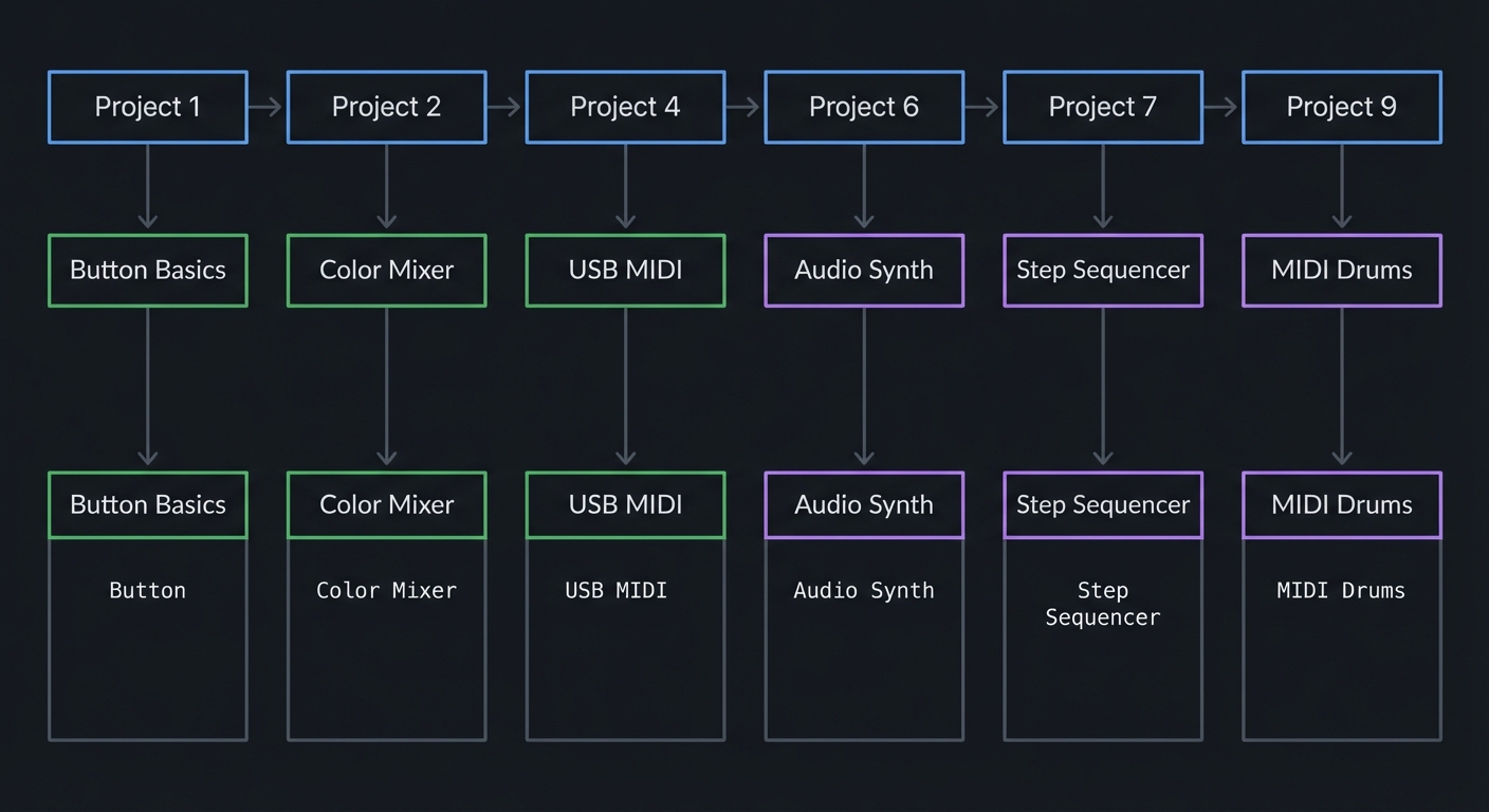
| Time: 3-4 weeks | Focus: Musical applications |
Path B: Embedded Systems Deep-Dive
Project 1 → Project 3 → Project 5 → Project 11 → Project 12 → Project 14
   │           │           │            │            │            │
   ▼           ▼           ▼            ▼            ▼            ▼
 Basics     Accel.      Timer        Bare-Metal   GPIO         DMA
            I2C         Precision    Blink        Registers    Audio
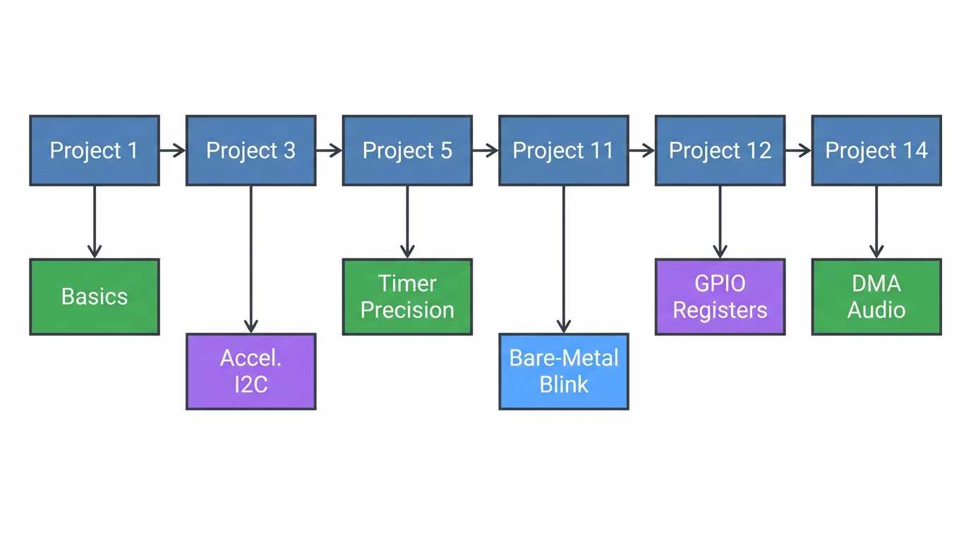
| Time: 6-8 weeks | Focus: Low-level understanding |
Path C: Complete Mastery (All Projects)
Complete in order: 1 → 2 → 3 → 4 → 5 → 6 → 7 → 8 → 9 → 10 → 11 → 12 → 13 → 14 → 15 → 16 → 17 → 18
| Time: 3-4 months | Focus: Full stack embedded expertise |
Project Validation & Performance Targets (Suggested)
These targets turn “it works” into “it feels pro.” Treat them as goals, not strict requirements.
| Project | Target Behavior | Quick Validation |
|---|---|---|
| 1. Button-LED Matrix | <10 ms response time per press | Tap rapidly; no missed events |
| 2. RGB Color Mixer | Smooth gradients, no color banding | Sweep sliders → smooth fade |
| 3. Accelerometer Light Show | Stable updates at 50–100 Hz | Tilt board → smooth motion |
| 4. USB MIDI Controller | <10 ms perceived latency | Tap pads → DAW responds instantly |
| 5. Metronome | <1 ms jitter at 120 BPM | Compare to DAW metronome |
| 6. Poly Synth | 6–8 voices at 44.1 kHz without glitches | Hold chords; no crackles |
| 7. Drum Sequencer | <2 ms step jitter | Run 16-step loop → tight timing |
| 8. FFT Visualizer | ~60 FPS display update | Play music → stable bars |
| 9. Sample Player | <20 ms trigger latency | Rapid retrigger test |
| 10. Theremin | Stable pitch with slow hand motion | Move hand slowly; no stepping |
| 11. Bare-Metal Blink | Deterministic timing via registers | Scope GPIO → stable period |
| 12. NeoPixel Driver | Clean 800 kHz waveforms | Logic analyzer on data pin |
| 13. UART Console | Error-free at target baud | Send 1,000 chars, no loss |
| 14. DAC Audio | Clean sine at 1 kHz | Audio out → no DC offset |
| 15. I2C Driver | No NACKs in normal operation | Read 1,000 samples cleanly |
| 16. DAW Controller | Stable mapping, no stuck notes | Session stress test |
| 17. Audio Visualizer | Stable frame rate + audio pipeline | Long run without drift |
| 18. Bootloader | Safe update + recovery path | Flash, reboot, fallback works |
Success Metrics: Knowing You’ve Mastered It
These metrics transform “I finished the projects” into “I genuinely understand embedded systems.” Use them to assess your mastery and identify gaps.
Conceptual Mastery Indicators
You’ve achieved conceptual mastery when you can answer these questions without looking them up:
| Concept Area | Mastery Indicator |
|---|---|
| ARM Cortex-M4 | You can explain the complete boot sequence from power-on to main(). You know what the vector table is, where it lives (0x00000000), and what happens when an interrupt fires. You can sketch the memory map from Flash to peripheral registers. |
| NeoPixel Protocol | You can calculate the exact timing for a ‘1’ bit (800 ns HIGH, 450 ns LOW) and explain why ±150 ns tolerance exists. You understand why you can’t bit-bang NeoPixels from Python. You know the reset time (>50 μs) and can debug color-order issues (GRB vs RGB). |
| I2C Communication | You can draw the complete transaction for reading a register: START → Address+W → Register → Repeated START → Address+R → Data → NACK → STOP. You understand clock stretching, multi-master arbitration, and why pull-ups are required. |
| Digital Audio | You can derive the Nyquist theorem (fs ≥ 2·fmax) and explain aliasing with a concrete example. You know why 44.1 kHz became the standard (NTSC video frame rate math). You can calculate buffer sizes for a given latency target. |
| USB MIDI | You can explain the complete USB enumeration sequence (RESET → SETUP → GET_DESCRIPTOR → SET_ADDRESS → SET_CONFIGURATION). You know the MIDI message format (status byte + 0-2 data bytes) and can decode a Note On message in hex. |
| Memory Mapping | You can explain why peripherals appear at specific addresses (0x40000000 range) and how the CPU doesn’t distinguish between RAM and memory-mapped registers. You understand volatile and why it’s critical for hardware access. |
| DMA | You can describe a complete DMA transfer: CPU sets up descriptor (source, destination, count) → Trigger fires → DMAC moves data without CPU → Interrupt on completion. You know the difference between beat/burst/block transfers and when to use circular buffers. |
| Button Matrix | You can calculate the scan rate for a 4×8 matrix (8 columns × debounce time) and explain why diodes prevent ghosting. You understand N-key rollover and can identify anti-ghosting patterns in a schematic. |
Practical Skills Assessment
Level 1: Beginner (CircuitPython Projects 1-5 Complete)
- You can write CircuitPython code that responds to button presses within 50 ms
- You understand how to use libraries (
import neopixel,import board) but know what’s happening underneath - You can read I2C sensor data (ADXL343) and interpret the raw values
- You can send USB MIDI messages and see them in a DAW
- You can troubleshoot basic issues (library imports, pin assignments, timing delays)
Level 2: Intermediate (Arduino Projects 6-10 Complete)
- You can synthesize audio at 44.1 kHz without glitches using the Audio library
- You understand interrupt-driven programming and can write an ISR that doesn’t block
- You can design a state machine for a step sequencer with proper timing
- You can use FFT to analyze audio in real-time and visualize it on LEDs
- You can debug timing issues with Serial.print() and understand interrupt priorities
Level 3: Advanced (Bare-Metal Projects 11-15 Complete)
- You can configure GPIO pins by writing to registers (PORT, DIRSET, OUTSET) without libraries
- You can bit-bang the NeoPixel protocol with precise timing using inline assembly or compiler intrinsics
- You can implement a UART driver from scratch (configure SERCOM, handle interrupts, manage buffers)
- You can configure the DAC to generate audio (set reference, enable, write samples at 44.1 kHz)
- You can write an I2C master driver that handles ACK/NACK, START/STOP, and multi-byte transfers
- You read datasheets fluently (SAMD51 datasheet, WS2812B timing, ADXL343 register map)
Level 4: Expert (Integration Projects 16-18 Complete)
- You can design a multi-peripheral system (LEDs + Audio + MIDI + I2C) without resource conflicts
- You understand DMA channel priorities and can configure descriptor chains for audio
- You can implement a USB bootloader that safely updates firmware and recovers from bad flashes
- You can profile code execution (instruction cycles, memory bandwidth) and optimize hot paths
- You can use a logic analyzer to debug protocol issues (I2C clock stretching, SPI mode mismatches)
Portfolio Readiness Criteria
Your portfolio is interview-ready when it includes:
- GitHub Repository with 3-5 Best Projects
- Clean, well-commented code (not just “it works” dumps)
- README with demo videos/GIFs showing real hardware operation
- Schematic or wiring diagram (Fritzing, KiCad, or hand-drawn)
- Build instructions that someone else can follow
- Recommended projects to showcase: Project 6 (Synth), Project 8 (FFT), Project 12 (Bare-Metal NeoPixel), Project 16 (DAW Controller)
- Technical Blog Posts or Documentation (2-3 writeups)
- “How I Implemented Real-Time Audio Synthesis on a Cortex-M4”
- “Bare-Metal NeoPixel Driver: Bit-Banging 800 kHz with Inline Assembly”
- “Building a USB MIDI Controller: From CircuitPython to Bare-Metal”
- Include scope captures, logic analyzer traces, performance metrics
- Explain problems you hit and how you debugged them
- Demo Video (2-4 minutes)
- Show the hardware working in real-time (button presses, LED animations, audio output)
- Narrate what’s happening at the hardware/software level
- Point out interesting implementation details (DMA setup, interrupt handling, timing)
- Upload to YouTube/Vimeo with timestamps in description
- Code Quality Indicators
- No
delay()or blocking loops in interrupt handlers - Proper use of
volatilefor hardware registers - Consistent naming (SCREAMING_SNAKE_CASE for defines, camelCase for variables)
- Hardware abstraction layers (HAL) for reusable peripherals
- Error handling (check return values, validate input ranges)
- No
Interview Preparation Targets
You’re ready for embedded systems interviews when you can confidently answer:
Cortex-M Architecture:
- “Walk me through what happens from power-on reset to the first instruction in
main().” - “Explain the difference between the MSP and PSP stack pointers.”
- “How does the NVIC prioritize interrupts, and what happens if two fire simultaneously?”
- “What’s the purpose of the SysTick timer, and how is it typically used?”
Peripheral Programming:
- “How would you bit-bang I2C on two GPIO pins? What’s the signaling sequence?”
- “Explain how DMA works. When would you use it vs polling vs interrupts?”
- “Why do we need pull-up resistors on I2C lines?”
- “What’s the difference between memory-mapped I/O and port-mapped I/O?”
Real-Time Constraints:
- “You’re generating audio at 44.1 kHz. How long do you have per sample? What’s your budget for processing?”
- “How do you ensure a task meets a hard real-time deadline?”
- “What causes jitter in embedded systems, and how do you measure it?”
Debugging & Tools:
- “How would you debug a system that crashes only after running for 2 hours?”
- “What tools would you use to verify the timing of an I2C transaction?”
- “How do you determine if your system is CPU-bound, memory-bound, or I/O-bound?”
Code Review Scenarios (they show you broken code):
- Identify race conditions (shared variables accessed from ISR and main loop without protection)
- Spot missing
volatilequalifiers on hardware registers - Recognize stack overflows (large local arrays, deep recursion)
- Find timing bugs (blocking operations in ISRs, tight polling loops)
Real-World Application Readiness
You can work professionally on embedded systems when:
| Capability | Evidence |
|---|---|
| Read Datasheets | You can parse a 1000-page datasheet (SAMD51), find the register you need, configure it correctly from the bit-field descriptions, and debug when it doesn’t work the first time. |
| Use Professional Tools | You’re comfortable with oscilloscopes, logic analyzers, JTAG debuggers (Segger J-Link, Black Magic Probe), and version control (Git branching/merging for firmware releases). |
| Estimate Project Timelines | You can scope a project (“8-channel MIDI drum pad controller with velocity sensing”) and give a realistic estimate (2-3 weeks for prototype, 6-8 weeks for production-ready). |
| Debug Hardware/Software Co-Issues | When a sensor “doesn’t work,” you can systematically isolate: Is power stable? Are pull-ups correct? Is the I2C address right? Is the timing valid? Is the code reading the right register? |
| Optimize for Constraints | You know when to optimize (audio inner loop, interrupt latency) and when not to (one-time init code). You can calculate memory usage before running out of RAM. You profile before guessing. |
| Ship Reliable Products | You write defensive code (check malloc return, validate input ranges, handle error cases). You test edge cases. You version firmware. You document errata and workarounds. |
Capstone Mastery Challenge
The ultimate test: Can you build this from scratch in 40 hours?
Project: USB MIDI DAW Controller with Audio Feedback
Requirements:
- 32 velocity-sensitive pads (ADC + button matrix)
- USB MIDI output (Note On/Off + CC messages)
- RGB LED feedback (color = note velocity, animations on transport controls)
- Audio click track output (44.1 kHz DAC, metronome at 40-240 BPM)
- I2C OLED display showing tempo, mode, and MIDI channel
- Firmware updateable via USB bootloader (no external programmer)
Skills Required:
- DMA for audio (no CPU overhead)
- Interrupt-driven ADC for velocity sensing
- Efficient button matrix scanning (8 columns, 4 rows)
- USB MIDI enumeration and message formatting
- NeoPixel DMA for smooth animations
- I2C display driver (SSD1306 protocol)
- Bootloader with safe flash updates
Success Criteria:
- <10 ms latency from pad hit to MIDI out
- Stable 44.1 kHz audio with <0.1% jitter
- No stuck notes or missed events under rapid play
- Survives 24-hour stress test without crashes
- Firmware updates without bricking
If you can build this, you’ve mastered the NeoTrellis M4 platform and are ready for professional embedded systems work.
Project List
Projects are ordered from foundational CircuitPython through Arduino audio to bare-metal C programming.
Project 1: Interactive Button-LED Matrix (CircuitPython)
- File: LEARN_NEOTRELLIS_M4_DEEP_DIVE.md
- Main Programming Language: CircuitPython (Python)
- Alternative Programming Languages: MicroPython, Arduino C++
- Coolness Level: Level 2: Practical but Forgettable
- Business Potential: 1. The “Resume Gold”
- Difficulty: Level 1: Beginner
- Knowledge Area: GPIO, Event Handling, Color Theory
- Software or Tool: NeoTrellis M4, Mu Editor
- Main Book: “CircuitPython Essentials” by Adafruit (online guide)
What you’ll build: A fully interactive 4x8 button grid where each button press triggers a unique LED color, with animations like ripples, fades, and rainbow waves responding to your touch.
Why it teaches NeoTrellis fundamentals: This forces you to understand the relationship between the button matrix scanning and NeoPixel addressing. You’ll learn how the 32 buttons map to the 32 LEDs, how event callbacks work in CircuitPython, and the basics of HSV vs RGB color spaces.
Core challenges you’ll face:
- Mapping buttons to LEDs → Understanding the matrix coordinate system (row, column)
- Handling simultaneous button presses → Learning event-driven programming with callbacks
- Creating smooth animations → Managing timing without blocking the main loop
- Color mathematics → Converting between RGB, HSV, and understanding gamma correction
Key Concepts:
- Event-driven programming: NeoTrellis M4 Overview - Adafruit
- NeoPixel control: “Adafruit NeoPixel Überguide” — LED addressing and timing
- HSV color space: “Computer Graphics from Scratch” by Gabriel Gambetta — Ch. 2
Difficulty: Beginner Time estimate: Weekend (4-8 hours) Prerequisites: Basic Python (variables, functions, loops), USB drive navigation
Real World Outcome
You’ll have a responsive light-up button pad that reacts instantly to touch. When you press any button, it lights up in a unique color. Press multiple buttons and they all respond independently. Release and watch fade animations. Tilt the board and watch colors shift.
Example Interaction:
Press button (0,0) → LED turns bright red
Press button (1,0) → LED turns orange (while red still lit)
Press button (2,0) → LED turns yellow
Release button (0,0) → Red LED fades out over 200ms
Press all buttons in row 0 → Rainbow gradient appears across row
Hold button (3,7) → LED pulses/breathes white

Serial output:
Button pressed: x=0, y=0, index=0
Setting LED 0 to RGB(255, 0, 0)
Button pressed: x=1, y=0, index=1
Setting LED 1 to RGB(255, 127, 0)
Button released: x=0, y=0, index=0
Fading LED 0...
When running the rainbow animation mode:
                    Visual Result (4x8 grid)
    ┌────┬────┬────┬────┬────┬────┬────┬────┐
Row0│ 🔴 │ 🟠 │ 🟡 │ 🟢 │ 🔵 │ 🟣 │ 💗 │ 🔴 │ ← Colors shift →
    ├────┼────┼────┼────┼────┼────┼────┼────┤
Row1│ 🟠 │ 🟡 │ 🟢 │ 🔵 │ 🟣 │ 💗 │ 🔴 │ 🟠 │
    ├────┼────┼────┼────┼────┼────┼────┼────┤
Row2│ 🟡 │ 🟢 │ 🔵 │ 🟣 │ 💗 │ 🔴 │ 🟠 │ 🟡 │
    ├────┼────┼────┼────┼────┼────┼────┼────┤
Row3│ 🟢 │ 🔵 │ 🟣 │ 💗 │ 🔴 │ 🟠 │ 🟡 │ 🟢 │
    └────┴────┴────┴────┴────┴────┴────┴────┘
    Animation flows diagonally at 60 FPS

Observable Behavior & Validation
- Button press → LED response should feel instant (<10 ms). Press two pads at once and both must light.
- Serial debug view (optional) confirms row/column mapping and debouncing.
Example serial output:
[BTN] row=2 col=5 index=21 state=DOWN
[LED] idx=21 rgb=(255,64,0) hsv=(18°,1.00,1.00)
The Core Question You’re Answering
“How does a microcontroller know when a physical button is pressed, and how does it control individual LEDs in a matrix?”
Before writing any code, understand this: The 32 buttons aren’t connected to 32 separate pins—that would require too many GPIO pins. Instead, they’re wired as a 4×8 matrix, scanned rapidly to detect which intersection is pressed. Similarly, the 32 NeoPixels are daisy-chained on a single data wire, receiving 24 bits each in sequence.
Concepts You Must Understand First
Stop and research these before coding:
- Matrix Scanning
- How can 32 buttons be read with fewer than 32 pins?
- What is “ghosting” in button matrices and how do diodes prevent it?
- Why does the scan happen faster than human perception?
- Book Reference: “Making Embedded Systems” Ch. 7 - Elecia White
- NeoPixel Addressing
- Why does the first LED in a chain get the first 24 bits?
- What’s the difference between physical position and logical index?
- Why does color order matter (GRB vs RGB)?
- Book Reference: “Adafruit NeoPixel Überguide” — Adafruit Learning System
- Event Callbacks
- What’s the difference between polling and event-driven design?
- Why are callbacks more efficient than checking state in a loop?
- How does the NeoTrellis library manage button state internally?
Questions to Guide Your Design
Before implementing, think through these:
- Data Organization
- How will you map button coordinates (x, y) to LED index?
- Will you store current LED colors in an array for animation?
- How will you track which buttons are currently held?
- Animation Architecture
- How will you fade LEDs without blocking button detection?
- What’s the relationship between main loop timing and animation smoothness?
- Should color calculations happen per-frame or be pre-computed?
- User Experience
- What should happen if the user presses faster than your animation cycle?
- How will you distinguish between tap, hold, and double-tap?
Thinking Exercise
Trace the Event Flow
Before coding, trace what happens when button (2, 3) is pressed:
1. Hardware level:
   - Matrix scanner activates row 2
   - Column 3 reads as connected
   - Interrupt generated (or polled state changes)

2. Library level:
   - NeoTrellis library detects state change
   - Callback function invoked with (x=2, y=3, edge=PRESSED)

3. Your code:
   - Calculate LED index: index = y * 8 + x = 3 * 8 + 2 = 26
   - Calculate color based on position
   - Set trellis.pixels[26] = (r, g, b)

4. NeoPixel level:
   - Library sends 32 × 24 = 768 bits to LED chain
   - LED 26 captures bits 625-648
Questions while tracing:
- Why is the index formula
y * 8 + xand notx * 4 + y? - What happens if you set the color before the library finishes scanning?
- How many microseconds does updating all 32 LEDs take?
The Interview Questions They’ll Ask
Prepare to answer these:
-
“Explain the difference between polling and interrupt-driven I/O. Which would you use for button detection and why?”
-
“Your LED animation is stuttering. What are the likely causes and how would you debug it?”
-
“If you needed to detect a button being held for 2 seconds, how would you implement that without blocking?”
-
“Why do NeoPixels use GRB color order instead of RGB? What problems can wrong color order cause?”
-
“A user reports that pressing certain button combinations causes wrong LEDs to light. What’s your first hypothesis?”
Hints in Layers
Hint 1: Starting Point
Begin with the Adafruit NeoTrellis example code. Understand the callback registration pattern: trellis.activate_key(x, y, NeoTrellis.EDGE_RISING).
Hint 2: Color Mapping Strategy Use HSV (Hue, Saturation, Value) for position-based colors. Hue from 0-255 maps to rainbow. Position (0,0) = Hue 0, position (3,7) = Hue 255.
Hint 3: Animation Without Blocking Store target colors and current colors separately. Each main loop iteration, move current colors slightly toward target. This is called “interpolation” or “tweening.”
Hint 4: Debugging Tools
Use print() statements to serial monitor. Print button coordinates and calculated indices. If LEDs light wrong positions, your index formula is incorrect.
Books That Will Help
| Topic | Book | Chapter |
|---|---|---|
| Event-driven design | “Making Embedded Systems” by Elecia White | Ch. 5 |
| Color theory for LEDs | “Programming Graphics” (online) | Color spaces |
| Python patterns | “Fluent Python” by Luciano Ramalho | Ch. 7 (functions) |
Common Pitfalls & Debugging
| Problem | Cause | Fix | Verification |
|---|---|---|---|
| LEDs don’t light | Brightness set to 0 | Set trellis.pixels.brightness = 0.2 |
Print brightness value |
| Wrong LED lights | Index formula wrong | Check index = y * width + x |
Print index, verify visually |
| Colors look wrong | GRB vs RGB mismatch | CircuitPython NeoPixel handles this | Test with (255,0,0) = red |
| Buttons unresponsive | Callbacks not registered | Call activate_key() for each button |
Print in callback to verify |
| Animation jerky | Blocking code in loop | Remove time.sleep(), use time delta |
Measure loop time |
Advanced Pitfalls
- Matrix ghosting if you disable the diode-aware scanning mode.
- Color mismatch if your color order is RGB vs GRB.
Learning Milestones
- Single button works → You understand the callback pattern and LED addressing
- All 32 buttons respond correctly → You’ve mastered the coordinate-to-index mapping
- Smooth animations running → You understand non-blocking timing and state management
Project 2: RGB Color Mixer Instrument (CircuitPython)
- File: LEARN_NEOTRELLIS_M4_DEEP_DIVE.md
- Main Programming Language: CircuitPython (Python)
- Alternative Programming Languages: Arduino C++, MicroPython
- Coolness Level: Level 3: Genuinely Clever
- Business Potential: 2. The “Micro-SaaS / Pro Tool”
- Difficulty: Level 1: Beginner
- Knowledge Area: Color Theory, State Machines, UI/UX Design
- Software or Tool: NeoTrellis M4, Mu Editor
- Main Book: “Interaction Design” by Preece, Rogers, Sharp
What you’ll build: A tactile color mixing interface where dedicated rows control Red, Green, Blue, and brightness. Pressing multiple buttons blends colors in real-time, with a preview area showing the result. Export the color as hex code via serial.
Why it teaches UI state management: This project forces you to think about multi-input state—what happens when the user changes red while green is still held? You’ll implement a state machine that tracks multiple simultaneous inputs and computes derived values.
Core challenges you’ll face:
- Multi-input tracking → Maintaining state for 32 possible simultaneous button states
- Value scaling → Mapping 8 buttons to 256 brightness levels
- Live preview → Updating display while user is still adjusting
- State persistence → Remembering the last color when buttons are released
Key Concepts:
- State machines: “Making Embedded Systems” Ch. 5 - Elecia White
- Color models: “Computer Graphics from Scratch” Ch. 2 - Gabriel Gambetta
- Human-computer interaction: “The Design of Everyday Things” - Don Norman
Difficulty: Beginner Time estimate: Weekend (6-10 hours) Prerequisites: Project 1 completed, understanding of RGB color model
Real World Outcome
Your NeoTrellis becomes a physical color picker. The grid is divided into functional zones:
                    Color Mixer Layout
    ┌────┬────┬────┬────┬────┬────┬────┬────┐
Row0│ R0 │ R1 │ R2 │ R3 │ R4 │ R5 │ R6 │ R7 │ ← Red (0-255)
    ├────┼────┼────┼────┼────┼────┼────┼────┤   Press R3 = Red 109
Row1│ G0 │ G1 │ G2 │ G3 │ G4 │ G5 │ G6 │ G7 │ ← Green (0-255)
    ├────┼────┼────┼────┼────┼────┼────┼────┤
Row2│ B0 │ B1 │ B2 │ B3 │ B4 │ B5 │ B6 │ B7 │ ← Blue (0-255)
    ├────┼────┼────┼────┼────┼────┼────┼────┤
Row3│ ▓▓ │ ▓▓ │ ▓▓ │ ▓▓ │ ▓▓ │ ▓▓ │ SAV│ CPY│ ← Preview + Actions
    └────┴────┴────┴────┴────┴────┴────┴────┘
                                   │     │
                              Save slot   Copy hex
                                         to serial

**Example Interaction:**
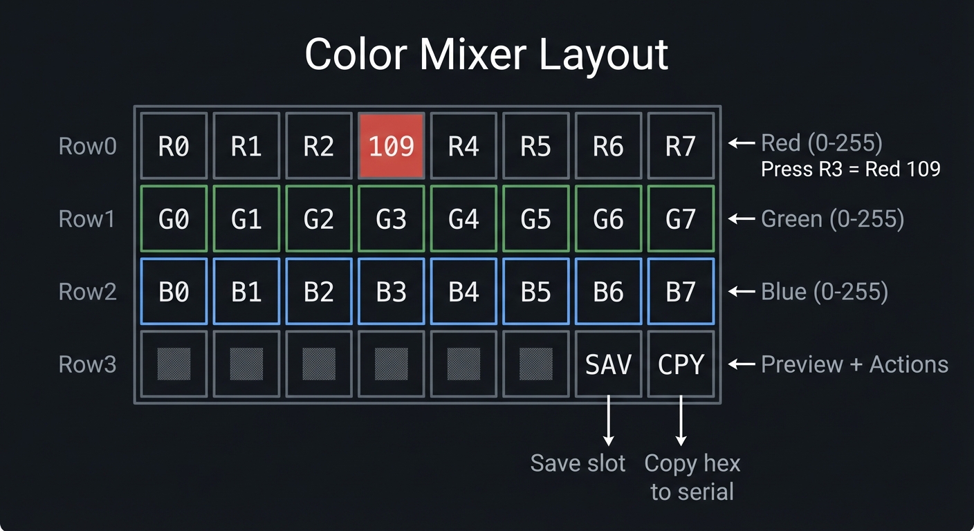 Press R4 → Red channel lights up (buttons 0-4 lit indicating value)
Red = (4/7) * 255 = 145
Press R4 → Red channel lights up (buttons 0-4 lit indicating value)
Red = (4/7) * 255 = 145
Press G2 → Green channel shows value Green = (2/7) * 255 = 73
Press B6 → Blue channel shows value Blue = (6/7) * 255 = 218
Row 3 preview → Shows mixed color: RGB(145, 73, 218) = purple
Press CPY button → Serial output: “Color: #9149DA RGB(145, 73, 218)”
---

##### Observable Behavior & Validation

- **Top row controls Red**, middle row Green, bottom row Blue (or your chosen mapping).
- **Smooth gradients** when you slide across pads — no banding or stepping.

Example serial output:

```text
[MIX] R=192 G=64 B=16  -> HEX #C04010
The Core Question You’re Answering
“How do you design a physical interface that allows continuous adjustment of multiple parameters simultaneously, while giving clear feedback?”
This is the fundamental challenge of instrument design. A piano doesn’t wait for you to release middle C before you can play G—it handles simultaneous input. Your color mixer must similarly track independent channel states.
Concepts You Must Understand First
Stop and research these before coding:
- State Machines
- What states can each color channel be in? (Idle, Adjusting, Locked)
- How do state transitions trigger actions?
- Why is explicit state management better than implicit boolean flags?
- Book Reference: “Making Embedded Systems” Ch. 5 - Elecia White
- Color Channel Independence
- Why are RGB channels orthogonal?
- How does 8-bit per channel create 16.7 million colors?
- What’s the perceptual difference between R:128 and R:255?
- Input Latching
- Should color persist after button release?
- How do you distinguish “user is adjusting” from “user is done”?
Questions to Guide Your Design
Before implementing, think through these:
- Value Representation
- 8 buttons for 256 values—how do you map this?
- Linear mapping (each button = 32) or logarithmic?
- How do you show the current value visually?
- Interaction Model
- Does pressing a new red button change red, or do you need to release first?
- What if user presses R3 then R5 without releasing R3?
- Should there be an “undo” button?
- Feedback Design
- How does the user know what value they’ve selected?
- Should unselected buttons be dimmed or off?
- How bright should the preview row be?
Thinking Exercise
Design the State Machine
Before coding, sketch the state machine for one color channel:
                    Red Channel State Machine

    ┌─────────────────────────────────────────────────┐
    │                                                 │
    │              ┌──────────┐                       │
    │   ┌──────────│   IDLE   │──────────┐            │
    │   │          │ value=0  │          │            │
    │   │          └────┬─────┘          │            │
    │   │ R(n)          │          R(n)  │            │
    │   │ pressed       │          pressed            │
    │   │               │                │            │
    │   ▼               │                ▼            │
    │ ┌─────────────────┴─────────────────────┐       │
    │ │              ACTIVE                   │       │
    │ │   value = n * (255/7)                │       │
    │ │   LEDs 0..n lit                      │       │
    │ └───────────────────────────────────────┘       │
    │   │                                             │
    │   │ Another R(m) pressed                        │
    │   │                                             │
    │   ▼                                             │
    │   Update value = m * (255/7)                    │
    │   Keep state ACTIVE                             │
    │                                                 │
    └─────────────────────────────────────────────────┘
Questions:
- When does value persist vs reset?
- What happens to the state machine when switching between colors?
- How do three independent state machines interact?
The Interview Questions They’ll Ask
-
“Describe the state machine for your color mixer. How did you handle simultaneous input from multiple channels?”
-
“Why did you choose the mapping between button position and color value? What alternatives did you consider?”
-
“Your user testing shows people expect the leftmost button to mean ‘off’ but your code treats it as the lowest non-zero value. How do you resolve this?”
-
“How would you extend this to support HSV or HSL color models?”
-
“The preview updates feel ‘laggy’. Walk me through how you’d profile and optimize the update path.”
Hints in Layers
Hint 1: Starting Point
Create three arrays: red_value, green_value, blue_value. Each starts at 0. Button presses in rows 0-2 update the corresponding array.
Hint 2: Value Mapping
Use integer division: value = (button_x * 255) // 7. Button 0 = 0, Button 7 = 255. The // is integer division in Python.
Hint 3: Visual Feedback For the red row, light buttons 0 through the selected one in red. Dim red (64,0,0) for unselected, bright red (255,0,0) for selected.
Hint 4: Preview Row
The preview row shows the mixed color. Update all 6 preview LEDs (indices 24-29) to (red_value, green_value, blue_value) whenever any channel changes.
Books That Will Help
| Topic | Book | Chapter |
|---|---|---|
| State machines | “Making Embedded Systems” by Elecia White | Ch. 5 |
| Color perception | “Interaction Design” by Preece et al. | Ch. 6 |
| Interface design | “The Design of Everyday Things” by Don Norman | Ch. 1-2 |
Common Pitfalls & Debugging
| Problem | Cause | Fix | Verification |
|---|---|---|---|
| Colors don’t match expectations | RGB order wrong | Verify with pure red (255,0,0) | Check single channel |
| Value jumps unexpectedly | Multiple button detection | Use edge detection, not level | Add debounce delay |
| Preview lags behind input | Update not called | Call preview update after any change | Add print statements |
| Can’t get pure white | Brightness too low | Increase pixels.brightness |
Test with (255,255,255) |
Advanced Pitfalls
- Gamma correction: raw linear RGB often looks “wrong” to the human eye.
- Palette banding when you only use a few discrete values.
Learning Milestones
- Single channel adjustable → You understand value mapping and LED feedback
- All three channels work independently → You’ve implemented parallel state tracking
- Smooth, responsive preview → You’ve optimized the update path
Project 3: Accelerometer-Controlled Light Show (CircuitPython)
- File: LEARN_NEOTRELLIS_M4_DEEP_DIVE.md
- Main Programming Language: CircuitPython (Python)
- Alternative Programming Languages: Arduino C++, MicroPython
- Coolness Level: Level 4: Hardcore Tech Flex
- Business Potential: 2. The “Micro-SaaS / Pro Tool”
- Difficulty: Level 2: Intermediate
- Knowledge Area: Sensors, I2C Protocol, Physics, Signal Processing
- Software or Tool: NeoTrellis M4, ADXL343 Accelerometer
- Main Book: “Making Embedded Systems” by Elecia White
What you’ll build: A motion-reactive light display where tilting the board shifts colors like liquid, shaking triggers sparkle effects, and tap detection changes modes. The LEDs respond to real physics—gravity pulls colors “down” to whichever edge is lowest.
Why it teaches sensor integration: This project forces you to understand the ADXL343 accelerometer’s I2C interface, interpret signed acceleration values, and convert raw sensor data into meaningful visualizations. You’ll learn sensor fusion basics and real-time signal processing.
Core challenges you’ll face:
- I2C communication → Reading from the ADXL343 at its 0x1D address
- Signed data interpretation → Understanding two’s complement for negative acceleration
- Coordinate transformation → Mapping 3D acceleration to 2D LED grid
- Tap detection → Configuring the accelerometer’s built-in tap detection registers
- Noise filtering → Smoothing sensor data without introducing lag
Key Concepts:
- I2C Protocol: “Making Embedded Systems” Ch. 7 - Elecia White
- Accelerometer physics: ADXL343 Datasheet - Analog Devices
- Signal filtering: “Digital Signal Processing” Ch. 1-2 - Smith
Difficulty: Intermediate Time estimate: 1 week (10-15 hours) Prerequisites: Project 1 completed, basic understanding of physics (acceleration, gravity)
Real World Outcome
Your NeoTrellis becomes a motion-sensitive light sculpture:
                    Tilt Response Visualization

    Board Flat:              Tilted Right:           Tilted Forward:
    ┌─────────────────┐      ┌─────────────────┐     ┌─────────────────┐
    │ ░ ░ ░ ░ ░ ░ ░ ░ │      │ ░ ░ ░ ░ ░ ░ ▓ █ │     │ ░ ░ ░ ░ ░ ░ ░ ░ │
    │ ░ ▓ ▓ ▓ ▓ ▓ ░ ░ │      │ ░ ░ ░ ░ ░ ░ ▓ █ │     │ ░ ░ ░ ░ ░ ░ ░ ░ │
    │ ░ ▓ ▓ ▓ ▓ ▓ ░ ░ │  →   │ ░ ░ ░ ░ ░ ░ ▓ █ │     │ ░ ░ ░ ░ ░ ░ ░ ░ │
    │ ░ ░ ░ ░ ░ ░ ░ ░ │      │ ░ ░ ░ ░ ░ ░ ▓ █ │     │ █ █ █ █ █ █ █ █ │
    └─────────────────┘      └─────────────────┘     └─────────────────┘
    "Blob" centered          Blob "flows" right      Blob "flows" forward
    X≈0, Y≈0                 X>0, Y≈0                X≈0, Y>0

**Serial Output:**
Acceleration: X=-0.05g Y=0.02g Z=1.00g (Board flat) Acceleration: X=0.42g Y=-0.03g Z=0.91g (Tilted right ~25°) Acceleration: X=0.71g Y=0.00g Z=0.71g (Tilted right ~45°) TAP DETECTED! Single tap Switching to mode: SPARKLE Acceleration: X=0.12g Y=0.89g Z=0.43g (Tilted forward ~60°) SHAKE DETECTED! Magnitude: 2.3g Triggering explosion effect!
**Tap → Changes display mode (liquid, sparkle, pulse)**
**Shake → Triggers special effect (explosion, reset)**
**Tilt → Continuously shifts color position**

---

##### Observable Behavior & Validation

- **Tilt left/right** should smoothly shift the color gradient across the grid.
- **Shake gesture** triggers a burst or sparkle mode.

Example serial output:

```text
[ACCEL] x=+0.12g y=-0.48g z=+0.97g
[MAP]   hue=210 sat=0.8 brightness=0.6
The Core Question You’re Answering
“How do you read physical sensor data over I2C and transform it into meaningful application behavior?”
The accelerometer outputs numbers in milligravities (thousandths of g). At rest, it reads approximately (0, 0, 1000) for X, Y, Z because gravity pulls down. Tilting changes these values. You must interpret these numbers as physical orientation.
Concepts You Must Understand First
Stop and research these before coding:
- I2C Protocol
- What are SDA and SCL? Why two wires?
- What is a 7-bit address? Why is ADXL343 at 0x1D?
- How do you read a 16-bit value from two 8-bit registers?
- Book Reference: “Making Embedded Systems” Ch. 7 - Elecia White
- Accelerometer Physics
- What does “1g” mean? What about “-1g”?
- When the board is flat, why is Z ≈ 1g?
- How does tilting change the X and Y values?
- Book Reference: ADXL343 Datasheet - Application Notes section
- Two’s Complement
- How are negative numbers represented in binary?
- Why is 0xFF not 255 but -1 in signed representation?
- How do you convert raw register bytes to signed integers?
- Tap Detection
- What physical motion constitutes a “tap”?
- How does the ADXL343 detect taps internally?
- What’s the difference between single and double tap?
Spec Anchor: ADXL343 is a 3-axis accelerometer with selectable ±2/±4/±8/±16g ranges and up to 13-bit resolution; data is accessible over I2C or SPI as 16-bit two’s complement. Source: https://www.analog.com/en/products/adxl343.html
Questions to Guide Your Design
Before implementing, think through these:
- Coordinate Mapping
- The accelerometer X axis vs the LED grid X axis—are they aligned?
- If you tilt “right,” which accelerometer axis increases?
- How will you map (-1g, +1g) range to (0, 7) LED columns?
- Response Characteristics
- Should small tilts be ignored (dead zone)?
- Should extreme tilts saturate at the edge?
- How fast should the visual update when tilting?
- Mode Switching
- How many display modes will you implement?
- How will the user know which mode is active?
- Should mode state persist after tap or cycle through?
Thinking Exercise
Map the Physics to Visual
Before coding, work out the math:
Scenario: Board tilted 30° to the right

Physics:
- Gravity vector g = (0, 0, -9.8) m/s² in world frame
- Board tilted 30° around Y axis
- Accelerometer reads in board frame

Calculation:
- X_accel = g × sin(30°) = 9.8 × 0.5 = 4.9 m/s² ≈ 0.5g
- Z_accel = g × cos(30°) = 9.8 × 0.866 = 8.5 m/s² ≈ 0.87g

What ADXL343 reports (in ±2g mode, 10-bit):
- X = 0.5g × 256 = 128 (scaled value)
- Z = 0.87g × 256 = 223

LED mapping:
- X range: -1g to +1g → LED columns 0 to 7
- X = 0.5g → column = (0.5 + 1) / 2 × 7 = 5.25 → column 5

Visual:
The "blob" should be in column 5-6 (right side of grid)
Questions:
- What happens at exactly 90° tilt? (X = 1g, Z = 0)
- How do you handle tilts beyond ±45°?
- What if the user rotates the board (changes which edge is “forward”)?
The Interview Questions They’ll Ask
-
“Explain the I2C read sequence for getting the X-axis acceleration. What bytes are sent and received?”
-
“The accelerometer outputs signed integers. How did you convert the raw bytes to a floating-point g value?”
-
“Your tap detection is either too sensitive or not sensitive enough. How would you tune it?”
-
“The LED response feels ‘jittery’ with sensor noise. What filtering approach did you use?”
-
“How would you add orientation detection (portrait vs landscape) to your design?”
Hints in Layers
Hint 1: Starting Point
Use the Adafruit_ADXL343 library. Initialize with accelerometer = adafruit_adxl34x.ADXL343(i2c). Read with x, y, z = accelerometer.acceleration.
Hint 2: Coordinate Alignment Print raw values while physically tilting the board. Note which axis increases when tilting right/left/forward/back. The axes may not match the LED grid intuition.
Hint 3: Simple Mapping
# Map acceleration (-10 to +10 m/s²) to column (0-7)
column = int((x + 10) / 20 * 8)
column = max(0, min(7, column))  # Clamp to valid range
Hint 4: Noise Reduction Use exponential moving average:
smoothed_x = 0.9 * smoothed_x + 0.1 * raw_x
The 0.9/0.1 ratio trades responsiveness for smoothness.
Books That Will Help
| Topic | Book | Chapter |
|---|---|---|
| I2C fundamentals | “Making Embedded Systems” by Elecia White | Ch. 7 |
| Accelerometer applications | ADXL343 Datasheet | Application Notes |
| Signal filtering | “DSP First” by McClellan et al. | Ch. 4 |
| Embedded sensors | “Sensors and Signal Conditioning” | Ch. 3 |
Common Pitfalls & Debugging
| Problem | Cause | Fix | Verification |
|---|---|---|---|
| I2C error on init | Wrong address or wiring | Check address 0x1D, verify SDA/SCL | Use I2C scanner |
| Values always near zero | Wrong scale factor | Check library returns m/s² not raw | Print raw values |
| Axes seem swapped | Board orientation mismatch | Print X/Y/Z while tilting physically | Map experimentally |
| Jittery display | Sensor noise | Add low-pass filter | Print filtered vs raw |
| Tap never triggers | Threshold too high | Lower THRESH_TAP register | Test sensitivity |
Advanced Pitfalls
- Noisy accelerometer without filtering (use simple IIR / moving average).
- Wrong axis orientation if you mounted the board rotated.
Learning Milestones
- Raw values printed correctly → You understand I2C communication and data format
- LEDs respond to tilt → You’ve correctly mapped sensor coordinates to display
- Smooth, responsive animations → You’ve mastered filtering and real-time updates
- Tap detection working → You understand interrupt-driven sensor events
Project 4: USB MIDI Controller (CircuitPython)
- File: LEARN_NEOTRELLIS_M4_DEEP_DIVE.md
- Main Programming Language: CircuitPython (Python)
- Alternative Programming Languages: Arduino C++
- Coolness Level: Level 4: Hardcore Tech Flex
- Business Potential: 3. The “Service & Support” Model
- Difficulty: Level 2: Intermediate
- Knowledge Area: USB Protocol, MIDI, Music Technology
- Software or Tool: NeoTrellis M4, DAW (Ableton/GarageBand/REAPER)
- Main Book: “MIDI: A Comprehensive Introduction” by Joseph Rothstein
What you’ll build: A class-compliant USB MIDI controller that appears as a MIDI input device on any computer. Buttons send note-on/off messages with velocity, the accelerometer maps to control change (CC) messages, and visual feedback shows what’s being transmitted.
Why it teaches USB protocols: This project demystifies how USB devices work. The NeoTrellis appears as a “Human Interface Device” variant—no drivers needed because it follows the USB MIDI class specification. You’ll understand enumeration, endpoints, and protocol compliance.
Core challenges you’ll face:
- USB enumeration → Understanding how the device identifies itself to the host
- MIDI message format → Constructing valid note-on, note-off, and CC messages
- Velocity mapping → Converting button press speed/force to MIDI velocity
- Latency management → Ensuring messages are sent within acceptable musical timing
- Visual feedback → Showing transmitted notes without interfering with timing
Key Concepts:
- USB MIDI specification: USB Device Class Definition for MIDI Devices
- MIDI protocol: “MIDI: A Comprehensive Introduction” Ch. 3-5 - Rothstein
- Real-time requirements: “Making Embedded Systems” Ch. 8 - White
Difficulty: Intermediate Time estimate: 1 week (10-15 hours) Prerequisites: Project 1 completed, basic understanding of musical notes
Real World Outcome
Your NeoTrellis becomes a professional MIDI controller:
                    MIDI Controller Layout

    ┌────┬────┬────┬────┬────┬────┬────┬────┐
Row0│ C3 │ C#3│ D3 │ D#3│ E3 │ F3 │ F#3│ G3 │  Channel 1
    ├────┼────┼────┼────┼────┼────┼────┼────┤  Notes 48-55
Row1│ G#3│ A3 │ A#3│ B3 │ C4 │ C#4│ D4 │ D#4│  Notes 56-63
    ├────┼────┼────┼────┼────┼────┼────┼────┤
Row2│ E4 │ F4 │ F#4│ G4 │ G#4│ A4 │ A#4│ B4 │  Notes 64-71
    ├────┼────┼────┼────┼────┼────┼────┼────┤
Row3│CC1 │CC2 │CC3 │CC4 │ Oct↓│Oct↑│Ch- │Ch+ │  Controls
    └────┴────┴────┴────┴────┴────┴────┴────┘
          ↑              ↑
    Mod/Express    Octave shift

**When connected to a DAW:**
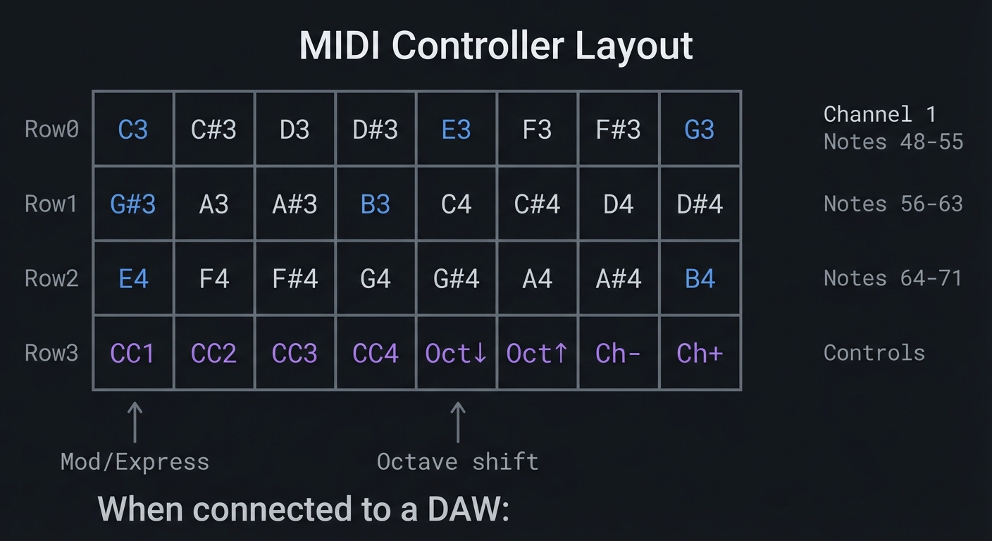 $ dmesg (Linux) or System Report (Mac):
USB MIDI Device: “NeoTrellis M4 MIDI”
Manufacturer: Adafruit
Ports: 1 In, 1 Out
$ dmesg (Linux) or System Report (Mac):
USB MIDI Device: “NeoTrellis M4 MIDI”
Manufacturer: Adafruit
Ports: 1 In, 1 Out
In DAW MIDI Monitor: 10:23:45.123 Note On Ch1 C4 Vel:100 10:23:45.234 Note On Ch1 E4 Vel: 87 10:23:45.345 Note On Ch1 G4 Vel: 92 10:23:45.456 Note Off Ch1 C4 Vel: 0 10:23:45.567 CC Ch1 CC1 Val: 64 (tilt-controlled) 10:23:45.678 Note Off Ch1 E4 Vel: 0 10:23:45.789 Note Off Ch1 G4 Vel: 0
Visual Feedback:
- Button pressed: LED turns white (sending note)
- Button held: LED pulses (sustaining)
- Velocity shown: Brighter = higher velocity
- CC active: Row 3 buttons glow proportionally ```
Observable Behavior & Validation
- Each pad sends Note On and Note Off (or CC) to a MIDI monitor/DAW.
- Velocity (if implemented) should correlate with press duration or pressure proxy.
Example MIDI monitor log:
Note On  ch=1 note=60 vel=100
Note Off ch=1 note=60 vel=0
The Core Question You’re Answering
“How does a USB device communicate with a computer without custom drivers, and what makes MIDI ‘class-compliant’?”
USB class compliance means the device follows a published specification. When the NeoTrellis says “I am a USB MIDI device,” the operating system already knows how to talk to it. No drivers needed. This is why you can plug any class-compliant MIDI controller into any computer.
Concepts You Must Understand First
Stop and research these before coding:
- USB Enumeration
- What happens in the first 100ms when you plug in a USB device?
- What are descriptors and why does the device send them?
- What’s the difference between high-speed and full-speed USB?
- Book Reference: “USB Complete” by Jan Axelson Ch. 4
- MIDI Protocol
- What are the three bytes in a Note On message?
- What’s the difference between a Channel Message and a System Message?
- Why does velocity 0 sometimes act as Note Off?
- Book Reference: “MIDI: A Comprehensive Introduction” Ch. 3
- Note Numbers
- What MIDI note number is Middle C? (Hint: there’s controversy—60 or 48 depending on convention)
- How do octaves map to note numbers?
- What’s the valid range of note numbers?
- Control Change Messages
- What is CC1 (Mod Wheel) vs CC7 (Volume)?
- Which CC numbers are “standard” vs “undefined”?
- Can CC messages be sent simultaneously with notes?
Spec Anchor: NeoTrellis M4 supports native USB MIDI in Arduino (class-compliant device behavior); design around that capability and test with a MIDI monitor. Source: https://learn.adafruit.com/adafruit-neotrellis-m4/overview
Questions to Guide Your Design
Before implementing, think through these:
- Note Mapping
- How will you map the 4×8 grid to musical notes?
- Chromatic scale? Specific scale (major, minor)?
- Should the layout be piano-like or grid-optimized?
- Velocity Generation
- The buttons are on/off—no pressure sensitivity. How will you determine velocity?
- Time between press start and full press? Random? Fixed?
- What’s a musically useful velocity range?
- Visual Latency
- Updating LEDs takes time (~1ms for 32 pixels). When do you update?
- Before MIDI send (visual before sound) or after?
- Does visual update affect MIDI timing?
Thinking Exercise
Construct a MIDI Message
Before coding, construct the bytes manually:
Goal: Send Note On for Middle C (note 60) on Channel 1 at velocity 100

MIDI Note On format:
┌────────────────┬────────────────┬────────────────┐
│   Status Byte  │   Data Byte 1  │   Data Byte 2  │
│   1001 nnnn    │   0nnn nnnn    │   0vvv vvvv    │
│   └──┬──┘└─┬─┘ │   └────┬────┘  │   └────┬────┘  │
│   Note  Channel│      Note #    │    Velocity    │
│   On   (0-15)  │    (0-127)     │    (0-127)     │
└────────────────┴────────────────┴────────────────┘

For Channel 1 (0 in zero-indexed), Note 60, Velocity 100:
- Status: 1001 0000 = 0x90
- Note:   0011 1100 = 0x3C = 60
- Velocity: 0110 0100 = 0x64 = 100

Message: [0x90, 0x3C, 0x64]

Verify:
- 0x90: Note On, Channel 1 ✓
- 0x3C = 60: Middle C ✓
- 0x64 = 100: Strong velocity ✓
Questions:
- What would the message be for Note Off?
- How would you change the channel to Channel 10 (drums)?
- What happens if you send velocity 0 with Note On?
The Interview Questions They’ll Ask
-
“Explain the structure of a MIDI Note On message. How did you construct and send it via USB?”
-
“Your controller has noticeable latency compared to commercial products. Where is the delay coming from?”
-
“How would you implement running status to reduce bandwidth for rapid note sequences?”
-
“The user wants to control both note velocity and aftertouch. How would you map this to buttons without pressure sensitivity?”
-
“Describe how USB enumeration works. What happens when the NeoTrellis is plugged in?”
Hints in Layers
Hint 1: Starting Point
Use adafruit_midi library. Initialize with midi = adafruit_midi.MIDI(midi_out=usb_midi.ports[1]). Send notes with midi.send(NoteOn(60, 100)).
Hint 2: Button to Note Mapping Simple chromatic starting at C3:
base_note = 48  # C3
note = base_note + (row * 8) + col
Hint 3: Simulated Velocity Without pressure, use timing. Start a timer on button edge, send Note On when stable (after debounce). Velocity = f(debounce_time). Faster press = higher velocity.
Hint 4: LED Feedback
Color by note: Use hue = (note % 12) * (255/12) to make each pitch class a distinct color. C = red, D = orange, etc.
Books That Will Help
| Topic | Book | Chapter |
|---|---|---|
| MIDI protocol | “MIDI: A Comprehensive Introduction” by Rothstein | Ch. 3-5 |
| USB fundamentals | “USB Complete” by Jan Axelson | Ch. 1-4, 11 |
| Real-time constraints | “Making Embedded Systems” by Elecia White | Ch. 8 |
Common Pitfalls & Debugging
| Problem | Cause | Fix | Verification |
|---|---|---|---|
| Device not recognized | USB descriptor issue | Reflash CircuitPython | Check dmesg/System Report |
| No MIDI output | Wrong USB port index | Try port[0] or port[1] | Print port names |
| Stuck notes | Note Off not sent | Always pair On with Off | Monitor in DAW |
| High latency | Visual update before MIDI | Send MIDI first, then update LED | Time with stopwatch app |
| Wrong notes | Off-by-one in mapping | Print note numbers | Use MIDI monitor |
Advanced Pitfalls
- Stuck notes if you miss Note Off or lose USB connection.
- Channel mismatch when DAW is listening on a different MIDI channel.
Learning Milestones
- Device appears in DAW → You understand USB enumeration and class compliance
- Notes trigger sounds → You’ve correctly constructed MIDI messages
- All 32 buttons work → You’ve mastered the button-to-note mapping
- Visual feedback matches output → You’ve synchronized display with transmission
Project 5: Precision Timer and Metronome (CircuitPython + Low-Level)
- File: LEARN_NEOTRELLIS_M4_DEEP_DIVE.md
- Main Programming Language: CircuitPython with low-level access
- Alternative Programming Languages: Arduino C++, Bare-metal C
- Coolness Level: Level 3: Genuinely Clever
- Business Potential: 2. The “Micro-SaaS / Pro Tool”
- Difficulty: Level 2: Intermediate
- Knowledge Area: Timer Peripherals, Real-Time Systems, Audio Timing
- Software or Tool: NeoTrellis M4
- Main Book: “Making Embedded Systems” by Elecia White
What you’ll build: A rock-solid BPM (beats per minute) metronome that uses hardware timers for precise timing, outputs audio clicks through the DAC, visual beats on LEDs, and can sync to external MIDI clock. Accuracy must be within 0.1% of target BPM.
Why it teaches timer fundamentals: This project forces you to understand the difference between software timing (time.sleep()) and hardware timer peripherals. You’ll learn why time.sleep(0.5) doesn’t give you exactly 500ms, and how to achieve microsecond-accurate timing.
Core challenges you’ll face:
- Timer drift → Understanding why software loops accumulate timing errors
- Hardware timer configuration → Setting prescaler and period for exact frequencies
- Interrupt-driven design → Moving timing-critical code to interrupt context
- DAC audio output → Generating click sounds without CPU involvement
- Multi-rate synchronization → LED update rate vs audio sample rate vs BPM
Key Concepts:
- Timer peripherals: SAMD51 Datasheet TC/TCC sections
- Interrupt latency: “Making Embedded Systems” Ch. 8 - White
- Real-time systems: “Real-Time Systems” by Liu - Ch. 1-3
Difficulty: Intermediate Time estimate: 1-2 weeks (15-20 hours) Prerequisites: Projects 1-4 completed, understanding of frequency/period relationship
Real World Outcome
Your NeoTrellis becomes a professional-grade metronome:
                    Metronome Display

    ┌────┬────┬────┬────┬────┬────┬────┬────┐
Row0│ ▓▓ │ ░░ │ ░░ │ ░░ │ ▓▓ │ ░░ │ ░░ │ ░░ │  Beat visualization
    ├────┼────┼────┼────┼────┼────┼────┼────┤  (4/4 time signature)
Row1│1 2 0│    │    │    │    │    │    │    │  BPM Display
    ├────┼────┼────┼────┼────┼────┼────┼────┤  (7-segment style)
Row2│ << │ <  │ ▶  │ >  │ >> │    │ TAP│SYNC│  Controls
    ├────┼────┼────┼────┼────┼────┼────┼────┤
Row3│ 4/4│ 3/4│ 6/8│7/8 │BEAT│SUBD│TRIP│    │  Time signatures
    └────┴────┴────┴────┴────┴────┴────┴────┘

Controls:
- << / >> : BPM ± 10
- < / >   : BPM ± 1
- ▶       : Start/Stop
- TAP     : Tap tempo (average of last 4 taps)
- SYNC    : Sync to incoming MIDI clock

**Serial Output:**
Metronome initialized Hardware Timer TC3 configured: Prescaler: 1024 Period: 58593 (for 120 BPM) Actual frequency: 2.0000 Hz Error: 0.0001%
Running at 120 BPM (4/4) Beat 1 | ████░░░░░░░░ | +0.023ms drift Beat 2 | ░░░░████░░░░ | +0.018ms drift Beat 3 | ░░░░░░░░████ | +0.025ms drift Beat 4 | ░░░░░░░░████ | +0.021ms drift
Tap tempo: 4 taps detected Intervals: 502ms, 498ms, 501ms Average: 500.33ms Calculated BPM: 119.92
MIDI Clock received: syncing… External tempo: 125.0 BPM (locked)
**Audio output**: Clean click sound through headphone jack, precisely on each beat.

---

##### Observable Behavior & Validation

- **LED pulse + audio click** should be perfectly aligned.
- **Tempo drift** should be imperceptible over 1–2 minutes.

Example serial output:

```text
[TICK] bpm=120 interval_us=500000 drift_us=+12
The Core Question You’re Answering
“Why does
time.sleep()accumulate timing errors, and how do hardware timers achieve precise, drift-free timing?”
Software timing is fundamentally flawed for precision work. Consider:
while True:
    do_beat()      # Takes 5ms (variable!)
    time.sleep(0.5)  # Sleep 500ms
    # Total: 505ms, not 500ms
    # After 100 beats: 500ms accumulated error!
Hardware timers run independently of software execution time. They count clock cycles directly, guaranteeing precision.
Concepts You Must Understand First
Stop and research these before coding:
- Timer Architecture
- What’s the relationship between CPU clock, prescaler, and timer frequency?
- What’s a timer period/compare register?
- How does a timer generate interrupts?
- Book Reference: SAMD51 Datasheet, TC chapter
- Prescaler Mathematics
- If CPU clock is 120MHz and prescaler is 1024, what’s the timer input frequency?
- For 120 BPM (2 beats/sec), what period value do you need?
- What’s the maximum period length with different prescaler values?
- Interrupt Context
- What code runs in “interrupt context” vs “main context”?
- Why must interrupt handlers be fast?
- What’s “interrupt latency” and why does it matter?
- Book Reference: “Making Embedded Systems” Ch. 8
- DAC Timing
- How do you generate audio samples at a fixed rate?
- What’s the relationship between sample rate and audio quality?
- How do DMA transfers help with timing?
Questions to Guide Your Design
Before implementing, think through these:
- Timer Selection
- The SAMD51 has multiple timer types (TC, TCC). Which one for BPM timing?
- What resolution do you need for 30-300 BPM range?
- How will you handle BPM changes without stopping the timer?
- Audio Click Generation
- What waveform makes a good “click”? (Sine burst, noise burst, frequency sweep?)
- How many samples for a 10ms click at 44.1kHz?
- Should click generation be in interrupt context or pre-computed?
- Visual Synchronization
- The LED update takes ~1ms. When do you trigger it relative to the audio?
- Should LEDs update in the timer interrupt or main loop?
Thinking Exercise
Calculate Timer Values
Before coding, work out the math for 120 BPM:
Given:
- CPU Clock: 120 MHz = 120,000,000 Hz
- Desired BPM: 120 (= 2 beats per second)
- Beat period: 1/2 = 0.5 seconds = 500,000 μs

Timer calculation:
- Prescaler options: 1, 2, 4, 8, 16, 64, 256, 1024
- Timer input frequency = CPU Clock / Prescaler

With Prescaler = 1024:
- Timer frequency = 120,000,000 / 1024 = 117,187.5 Hz
- Ticks per beat = 117,187.5 × 0.5 = 58,593.75

Since period must be integer, use 58594:
- Actual beat period = 58594 / 117187.5 = 0.50000426 seconds
- Actual BPM = 60 / 0.50000426 = 119.999 BPM
- Error = 0.0008%

16-bit timer max = 65535
With Prescaler 1024, max period = 65535 / 117187.5 = 0.559 seconds
Min BPM = 60 / 0.559 = 107 BPM

For slower tempos (< 107 BPM), use 32-bit timer or different prescaler.
Questions:
- What prescaler gives the best resolution for tempo fine-tuning?
- How would you implement fractional BPM (e.g., 120.5)?
- What’s the jitter if you update the period while the timer is running?
The Interview Questions They’ll Ask
-
“Explain why
time.sleep()causes timing drift and how hardware timers solve this.” -
“Calculate the prescaler and period values needed for a 90 BPM metronome with < 0.01% error.”
-
“Your interrupt handler takes 50μs but you’re getting timing errors. What’s happening?”
-
“How would you implement tap tempo? What statistical method handles outliers?”
-
“The user wants to sync to external MIDI clock. How does MIDI clock work and how do you lock to it?”
Hints in Layers
Hint 1: Starting Point
In CircuitPython, you can access hardware timers, but it’s limited. Consider using the pulseio or audiopwmio for timing. For true hardware timer access, you may need Arduino.
Hint 2: Tap Tempo Algorithm Store the last N tap timestamps. Calculate intervals between consecutive taps. Throw out outliers (> 2× average). Average remaining intervals. BPM = 60000 / average_interval_ms.
Hint 3: Click Sound Generation A simple click: exponentially decaying sine wave.
for i in range(441):  # 10ms at 44.1kHz
    envelope = exp(-i/100)
    sample = sin(2*pi*1000*i/44100) * envelope
    buffer[i] = int(sample * 2047 + 2048)
Hint 4: Visual Sync Trigger LED update from the same timer interrupt that plays the click. Set a flag in interrupt, process in main loop. This ensures visual and audio stay synchronized.
Books That Will Help
| Topic | Book | Chapter |
|---|---|---|
| Timer peripherals | SAMD51 Datasheet | TC/TCC chapters |
| Interrupt handling | “Making Embedded Systems” by Elecia White | Ch. 8 |
| Real-time systems | “Real-Time Systems” by Jane Liu | Ch. 1-3 |
| Audio timing | “Real-Time DSP” by Kuo & Gan | Ch. 2 |
Common Pitfalls & Debugging
| Problem | Cause | Fix | Verification |
|---|---|---|---|
| Tempo drifts over time | Using time.sleep() |
Use hardware timer | Measure 100 beats, calculate actual BPM |
| Audio clicks have pops | Buffer underrun | Use double buffering | Listen for glitches |
| Visual lags behind audio | LED update in main loop | Set flag in ISR, update immediately | Record with phone, check sync |
| Can’t get slow tempos | Timer period overflow | Use larger prescaler or 32-bit timer | Calculate max period |
| Tap tempo erratic | No outlier rejection | Filter extreme intervals | Print all intervals |
Advanced Pitfalls
- Timer drift if you compute intervals with milliseconds instead of microseconds.
- Blocking delays that add jitter to the click.
Learning Milestones
- Software metronome works → You understand the basic timing requirement
- Hardware timer configured → You’ve mastered prescaler/period calculations
- Audio clicks are precise → You’ve integrated DAC output with timer
- Tap tempo accurate → You’ve implemented statistical tempo detection
- Visual perfectly synced → You’ve coordinated multiple output systems
Project 6: Polyphonic Synthesizer (Arduino + PJRC Audio)
- File: LEARN_NEOTRELLIS_M4_DEEP_DIVE.md
- Main Programming Language: Arduino C++
- Alternative Programming Languages: Bare-metal C, Rust (embedded)
- Coolness Level: Level 5: Pure Magic (Super Cool)
- Business Potential: 4. The “Open Core” Infrastructure
- Difficulty: Level 3: Advanced
- Knowledge Area: Digital Audio Synthesis, DSP, Real-Time Systems
- Software or Tool: Arduino IDE, PJRC Audio Library (Adafruit fork)
- Main Book: “The Audio Programming Book” by Richard Boulanger
What you’ll build: A 4-voice polyphonic synthesizer with multiple waveforms (sine, saw, square, triangle), ADSR envelopes, low-pass filter with resonance, and LFO modulation. Each button plays a note, multiple buttons create chords, and the accelerometer controls filter cutoff.
Why it teaches audio DSP: This project takes you inside audio synthesis. You’ll understand how digital waveforms are generated sample-by-sample, how envelopes shape sounds, and how filters modify frequency content—all in real-time at 44.1kHz.
Core challenges you’ll face:
- Voice allocation → Managing which oscillator plays which note when only 4 voices are available
- ADSR envelope → Understanding Attack-Decay-Sustain-Release for musical shaping
- Filter implementation → Understanding how low-pass filters work mathematically
- Real-time constraints → Computing audio samples fast enough (< 22.6μs per sample)
- Audio library architecture → Understanding the node-graph model of audio processing
Key Concepts:
- Digital oscillators: “The Audio Programming Book” Ch. 1-2 - Boulanger
- Envelope generators: “Designing Sound” Ch. 9 - Farnell
- Filter theory: “Introduction to Digital Filters” by Julius O. Smith III (online)
- PJRC Audio: Audio System Design Tool documentation
Difficulty: Advanced Time estimate: 2-3 weeks (20-30 hours) Prerequisites: Projects 1-5 completed, basic understanding of sound waves and frequency
Real World Outcome
Your NeoTrellis becomes a real musical instrument:
                    Synthesizer Architecture

    ┌──────────────────────────────────────────────────────────────────┐
    │                         Audio Graph                              │
    │                                                                  │
    │  ┌──────────┐   ┌──────────┐   ┌──────────┐   ┌──────────┐      │
    │  │ Voice 1  │   │ Voice 2  │   │ Voice 3  │   │ Voice 4  │      │
    │  │┌────────┐│   │┌────────┐│   │┌────────┐│   │┌────────┐│      │
    │  ││  OSC   ││   ││  OSC   ││   ││  OSC   ││   ││  OSC   ││      │
    │  │└───┬────┘│   │└───┬────┘│   │└───┬────┘│   │└───┬────┘│      │
    │  │    │     │   │    │     │   │    │     │   │    │     │      │
    │  │┌───▼────┐│   │┌───▼────┐│   │┌───▼────┐│   │┌───▼────┐│      │
    │  ││  ENV   ││   ││  ENV   ││   ││  ENV   ││   ││  ENV   ││      │
    │  │└───┬────┘│   │└───┬────┘│   │└───┬────┘│   │└───┬────┘│      │
    │  └────┼─────┘   └────┼─────┘   └────┼─────┘   └────┼─────┘      │
    │       │              │              │              │             │
    │       └──────────────┴──────┬───────┴──────────────┘             │
    │                             │                                    │
    │                      ┌──────▼──────┐                             │
    │                      │    MIXER    │                             │
    │                      └──────┬──────┘                             │
    │                             │                                    │
    │     ┌────────────┐   ┌──────▼──────┐                             │
    │     │    LFO     │──▶│   FILTER    │◀── Accelerometer            │
    │     └────────────┘   └──────┬──────┘                             │
    │                             │                                    │
    │                      ┌──────▼──────┐                             │
    │                      │   OUTPUT    │──▶ Headphone Jack           │
    │                      │   (DAC)     │                             │
    │                      └─────────────┘                             │
    └──────────────────────────────────────────────────────────────────┘

**Button Layout:**
    ┌────┬────┬────┬────┬────┬────┬────┬────┐
Row0│ C3 │ C#3│ D3 │ D#3│ E3 │ F3 │ F#3│ G3 │ ← Note triggers
    ├────┼────┼────┼────┼────┼────┼────┼────┤    (24 notes)
Row1│ G#3│ A3 │ A#3│ B3 │ C4 │ C#4│ D4 │ D#4│
    ├────┼────┼────┼────┼────┼────┼────┼────┤
Row2│ E4 │ F4 │ F#4│ G4 │ G#4│ A4 │ A#4│ B4 │
    ├────┼────┼────┼────┼────┼────┼────┼────┤
Row3│WAVE│ A  │ D  │ S  │ R  │FILT│ LFO│ OCT│ ← Controls
    └────┴────┴────┴────┴────┴────┴────┴────┘

**Serial Output:**
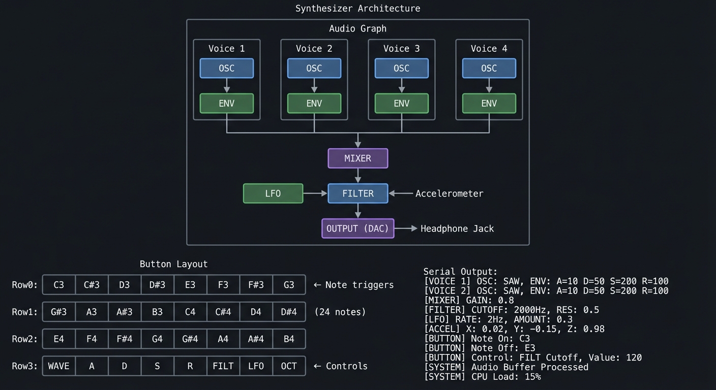 Audio System Design Tool Export:
4x AudioSynthWaveform (oscillators)
4x AudioEffectEnvelope (ADSR)
1x AudioMixer4 (voice mix)
1x AudioFilterStateVariable (filter)
1x AudioOutputAnalogStereo (DAC)
Audio System Design Tool Export:
4x AudioSynthWaveform (oscillators)
4x AudioEffectEnvelope (ADSR)
1x AudioMixer4 (voice mix)
1x AudioFilterStateVariable (filter)
1x AudioOutputAnalogStereo (DAC)
CPU Usage: 12.4% (at 4-voice polyphony) Memory: 8 audio blocks allocated
Note C4 (261.63 Hz) triggered → Voice 0 Envelope: Attack=50ms, Decay=100ms, Sustain=0.7, Release=300ms Note E4 (329.63 Hz) triggered → Voice 1 Note G4 (392.00 Hz) triggered → Voice 2 Playing C Major chord
Filter cutoff: 2000 Hz (tilt X = 0.3g) Filter resonance: 2.5 LFO → Filter: depth=500Hz, rate=2Hz
Note C4 released → Voice 0 entering release phase
**Audio Output**: Rich, musical tones through the headphone jack. Chords sound simultaneously.

---

##### Observable Behavior & Validation

- **Chord playback** should sustain 6–8 voices without crackle.
- **Filter sweeps** should feel smooth with no zipper noise.

Example serial output:

```text
[AUDIO] voices=6 cpu=32% mem_blocks=20/60
The Core Question You’re Answering
“How do computers generate sound, and how can you shape raw waveforms into musical tones?”
Every sound you hear from a computer starts as numbers—samples output 44,100 times per second. A sine wave at 440 Hz (note A4) is generated by computing sin(2π × 440 × t) for each sample. The PJRC Audio Library abstracts this into a node graph, but understanding what happens inside those nodes is essential.
Concepts You Must Understand First
Stop and research these before coding:
- Digital Audio Fundamentals
- What is a sample? What is sample rate?
- Why 44.1kHz? Why 16-bit? (Nyquist theorem, dynamic range)
- What’s the relationship between frequency and pitch?
- Book Reference: “The Audio Programming Book” Ch. 1
- Waveform Generation
- How do you compute a sine wave sample-by-sample?
- What’s a wavetable and why use it instead of calculating?
- How do sawtooth, square, and triangle waves differ harmonically?
- Book Reference: “Designing Sound” Ch. 3-5
- ADSR Envelopes
- What happens during Attack, Decay, Sustain, Release phases?
- How do envelope times affect musicality?
- What’s the difference between linear and exponential curves?
- Book Reference: “Designing Sound” Ch. 9
- Filters
- What does a low-pass filter do to a waveform?
- What is cutoff frequency? What is resonance (Q)?
- How do filters create “analog synth” sounds?
- Book Reference: “Introduction to Digital Filters” by Smith (online)
- Polyphony and Voice Allocation
- With N voices but M pressed keys (M > N), how do you decide what to play?
- What’s “voice stealing”? What strategies exist?
Spec Anchor: The PJRC Audio library streams CD‑quality audio (16‑bit, 44.1 kHz) and provides a visual design tool for patching audio graphs. Source: https://www.pjrc.com/teensy/td_libs_Audio.html
Questions to Guide Your Design
Before implementing, think through these:
- Audio Graph Architecture
- What objects do you need? (Oscillators, envelopes, mixers, filters)
- How do they connect? (Output of osc → input of envelope → mixer)
- The PJRC Audio Design Tool generates code—do you understand what it generates?
- Voice Management
- How will you track which voice is playing which note?
- When a note is released, when does the voice become available? (After release phase!)
- What happens if all 4 voices are active and a 5th note is pressed?
- Control Mapping
- How will buttons in row 3 control parameters?
- Should parameters change immediately or smoothly interpolate?
- How will the accelerometer map to filter cutoff?
Thinking Exercise
Trace Audio Sample Generation
Before coding, trace what happens for ONE sample:
Time t = 0.001 seconds (sample #44 at 44.1kHz)
Voice 0 playing A4 (440 Hz)

1. Oscillator computes:
   phase = (440 / 44100) * 2π * 44 = 2.7646 radians
   For sine: sample = sin(2.7646) = 0.371

2. Envelope applies:
   We're at t=1ms, in Attack phase (50ms total)
   envelope_level = t / attack_time = 0.001 / 0.050 = 0.02
   sample = 0.371 * 0.02 = 0.00742

3. Voice 0 output: 0.00742

4. Mixer combines all 4 voices:
   output = (voice0 + voice1 + voice2 + voice3) / 4
   If only voice 0 active: output = 0.00742 / 4 = 0.00186

5. Filter processes:
   (Complex IIR calculation—for now, assume passthrough)
   output = 0.00186

6. Convert to DAC value:
   dac_value = (output * 2047) + 2048 = 2052

7. DAC outputs 2052, which becomes ~1.65V (halfway between 0V and 3.3V)
Questions:
- Why divide by 4 in the mixer? (Prevent clipping when all voices are at full volume)
- Why does the envelope ramp up slowly? (Prevents clicks/pops)
- What happens if you skip the envelope? (Instantaneous starts sound unnatural)
The Interview Questions They’ll Ask
-
“Explain how you generate a 440 Hz sine wave at 44.1kHz sample rate. Show the math.”
-
“Your synth has 4 voices and 5 notes are pressed. Describe your voice allocation algorithm.”
-
“What’s the difference between a low-pass and high-pass filter? How does resonance create that ‘synth’ sound?”
-
“Your audio is ‘clicking’ at note starts. What’s causing this and how do you fix it?”
-
“The CPU usage jumps to 80% with complex waveforms. How would you optimize?”
Hints in Layers
Hint 1: Starting Point Use the PJRC Audio System Design Tool at https://www.pjrc.com/teensy/gui/. Create your audio graph visually, then export the code. The Adafruit NeoTrellis M4 examples include a basic synth.
Hint 2: Voice Structure Create a struct for each voice:
struct Voice {
  AudioSynthWaveform* osc;
  AudioEffectEnvelope* env;
  int8_t note;      // -1 if free
  uint32_t startTime;
};
Hint 3: Voice Allocation Simple algorithm: find first voice where note == -1. If none free, steal the oldest voice (smallest startTime).
Hint 4: Frequency Calculation
MIDI note to frequency: freq = 440.0 * pow(2.0, (note - 69) / 12.0)
Books That Will Help
| Topic | Book | Chapter |
|---|---|---|
| Audio synthesis | “The Audio Programming Book” by Boulanger | Ch. 1-4 |
| Sound design | “Designing Sound” by Andy Farnell | Ch. 3-9 |
| Digital filters | “Introduction to Digital Filters” by Smith | Online, Ch. 1-4 |
| Synth architecture | “Welsh’s Synthesizer Cookbook” | Ch. 1-5 |
Common Pitfalls & Debugging
| Problem | Cause | Fix | Verification |
|---|---|---|---|
| No sound | Audio objects not connected | Check AudioConnection |
Use Serial to print CPU% |
| Clicking at note start | No envelope attack | Ensure Attack > 0 | Slow attack to 100ms, listen |
| Distorted audio | Clipping (volume > 1.0) | Reduce mixer levels | Watch for flat-topped waveforms |
| Only one note plays | Voice allocation bug | Check voice state | Print voice note assignments |
| Filter doesn’t change | Wrong frequency units | Frequency in Hz, not normalized | Print cutoff value |
Advanced Pitfalls
- AudioMemory underruns cause crackles (increase blocks).
- Gain staging too hot leads to clipping at the DAC.
Learning Milestones
- Single oscillator makes sound → You understand the audio graph
- ADSR shapes the tone → You understand envelope generators
- 4-voice polyphony works → You’ve mastered voice allocation
- Filter responds to accelerometer → You’ve integrated sensor control
- Sounds musical and playable → You’ve tuned the synthesis parameters
Project 7: 8-Step Drum Machine Sequencer (Arduino)
- File: LEARN_NEOTRELLIS_M4_DEEP_DIVE.md
- Main Programming Language: Arduino C++
- Alternative Programming Languages: CircuitPython
- Coolness Level: Level 4: Hardcore Tech Flex
- Business Potential: 3. The “Service & Support” Model
- Difficulty: Level 3: Advanced
- Knowledge Area: Sequencing, Sample Playback, Rhythm Programming
- Software or Tool: Arduino IDE, PJRC Audio Library
- Main Book: “The Audio Programming Book” by Richard Boulanger
What you’ll build: An 8-step, 4-track drum sequencer where rows represent different drum sounds (kick, snare, hi-hat, clap) and columns represent beats. LEDs show current playback position, buttons toggle steps on/off. Tempo is adjustable, and patterns are saveable to flash.
Why it teaches sequencer architecture: Drum machines are fundamentally about timing and state management. You’ll understand how professional sequencers work—maintaining pattern state, triggering samples precisely on time, and managing the relationship between user interaction and audio playback.
Core challenges you’ll face:
- Step state management → Maintaining a 4×8 grid of on/off states
- Precise timing → Triggering samples exactly on beat, regardless of loop timing
- Sample playback → Loading and playing drum samples from flash
- Visual synchronization → LED playhead shows current step in sync with audio
- Pattern storage → Saving/loading patterns to non-volatile memory
Key Concepts:
- Step sequencing: Electronic music production fundamentals
- Sample playback: “The Audio Programming Book” Ch. 5
- Pattern storage: QSPI flash access on SAMD51
- Real-time scheduling: “Making Embedded Systems” Ch. 8
Difficulty: Advanced Time estimate: 2-3 weeks (20-30 hours) Prerequisites: Project 6 completed, understanding of BPM and rhythm
Real World Outcome
Your NeoTrellis becomes a classic drum machine:
                    Drum Machine Layout

    Step:  1    2    3    4    5    6    7    8
    ┌────┬────┬────┬────┬────┬────┬────┬────┐
Row0│ ██ │    │    │    │ ██ │    │    │    │ ← Kick   🔴
    ├────┼────┼────┼────┼────┼────┼────┼────┤         Red when active
Row1│    │    │ ██ │    │    │    │ ██ │    │ ← Snare  🔵
    ├────┼────┼────┼────┼────┼────┼────┼────┤
Row2│ ██ │ ██ │ ██ │ ██ │ ██ │ ██ │ ██ │ ██ │ ← Hi-Hat 🟡
    ├────┼────┼────┼────┼────┼────┼────┼────┤
Row3│    │    │    │ ██ │    │    │    │ ██ │ ← Clap   🟢
    └────┴────┴────┴────┴────┴────┴────┴────┘
         ↑
         Playhead (bright white column)

**Visual Feedback:**
- Step programmed: Track color (dim)
- Current step playing: White column overlay
- Step programmed + playing: Bright track color

**Serial Output:**
Drum Machine initialized Loaded 4 samples from QSPI flash: kick.wav: 4410 samples (100ms) snare.wav: 6615 samples (150ms) hihat.wav: 2205 samples (50ms) clap.wav: 3307 samples (75ms)
Pattern 1 loaded: Kick: [X . . . X . . .] Snare: [. . X . . . X .] Hi-Hat: [X X X X X X X X] Clap: [. . . X . . . X]
Playing at 120 BPM (step = 125ms) Step 1: KICK HIHAT Step 2: HIHAT Step 3: SNARE HIHAT Step 4: HIHAT CLAP Step 5: KICK HIHAT Step 6: HIHAT Step 7: SNARE HIHAT Step 8: HIHAT CLAP [Loop]
---

##### Observable Behavior & Validation

- **Playhead LED** advances at the exact tempo and loops seamlessly.
- **Accent steps** are visually brighter or audibly louder.

Example serial output:

```text
[SEQ] step=5 trig=KICK vel=120
The Core Question You’re Answering
“How do professional drum machines maintain precise timing while allowing real-time user interaction with the pattern?”
The challenge is that user input (button presses) is asynchronous, but drum triggers must be precisely timed to the beat. You can’t delay the beat to wait for a button handler. The solution involves separating the “pattern editing” system from the “playback engine” with clear interfaces between them.
Concepts You Must Understand First
Stop and research these before coding:
- Step Sequencing Fundamentals
- What’s the relationship between BPM, step length, and step resolution?
- At 120 BPM with 16th notes, how many milliseconds per step?
- What’s “swing” and how does it affect step timing?
- Sample Playback
- What’s a WAV file structure?
- How do you play a sample once (one-shot) vs looping?
- What happens when samples overlap (same drum hit before previous ends)?
- Book Reference: “The Audio Programming Book” Ch. 5
- Pattern State Management
- How do you represent a pattern? (2D array? Bitmask?)
- How do you modify the pattern while it’s playing?
- What’s the difference between “live record” and “step edit”?
- Flash Storage
- How does the 8MB QSPI flash work?
- What filesystem is used? (LittleFS, FatFS, raw?)
- How do you load samples at startup?
Questions to Guide Your Design
Before implementing, think through these:
- Data Structures
- How will you represent the pattern?
bool pattern[4][8]? Bitmask? - Where are samples stored during playback? (Memory? Stream from flash?)
- How do you handle multiple patterns?
- How will you represent the pattern?
- Timing Architecture
- What triggers the next step? (Timer interrupt? Main loop check?)
- How do you prevent audio glitches when editing the pattern?
- What’s the latency from button press to pattern update?
- User Experience
- How does the user know which step is currently playing?
- Can the user change tempo while playing?
- What feedback when toggling a step on/off?
Thinking Exercise
Design the Step Timing
Before coding, calculate the timing:
BPM = 120 (beats per minute)
4/4 time signature
8 steps = 2 beats (each step is 8th note)

Step duration:
- 1 beat = 60000ms / 120 BPM = 500ms
- 8 steps in 2 beats = 1000ms total
- 1 step = 1000ms / 8 = 125ms

Hardware timer approach:
- Timer fires every 125ms
- On interrupt:
  1. Advance step (0→1→2→...→7→0)
  2. Check pattern[track][step] for each track
  3. If true, trigger sample playback
  4. Update playhead LED

Button handling (separate from timing):
- On button press callback:
  1. Toggle pattern[row][col]
  2. Update LED for that cell
  3. (No timing impact!)
Questions:
- What happens if timer interrupt fires while button callback is running?
- Should you protect pattern array with a mutex? (On single-core, interrupts are enough)
- How do you prevent the playhead LED update from causing flicker?
The Interview Questions They’ll Ask
-
“Describe your timing architecture. How do you ensure drum hits are precisely on time?”
-
“The user wants to edit the pattern while it’s playing. How do you handle concurrent access to the pattern data?”
-
“Your drum machine has noticeable ‘jitter’ at high tempos. What’s causing this?”
-
“How do you handle the case where a drum sample is longer than one step, and the same drum is triggered again?”
-
“Describe how you load and manage samples from flash. What’s the tradeoff between loading all samples to RAM vs streaming?”
Hints in Layers
Hint 1: Starting Point
Use AudioPlayMemory for short samples stored in program flash, or AudioPlaySdRaw pattern for QSPI flash samples. The Audio library handles mixing automatically.
Hint 2: Pattern Representation
// Simple 2D array
bool pattern[4][8];

// Or compact bitmask (1 byte per track)
uint8_t pattern[4];  // pattern[track] & (1 << step)
Hint 3: Timer Setup Use a hardware timer for step advancement. In Arduino on SAMD51, use the TC/TCC peripherals. The Audio library uses some timers—check which are free.
Hint 4: Visual Feedback Don’t update all 32 LEDs every step—only update the previous step column (turn off playhead) and current step column (turn on playhead). This reduces flicker.
Books That Will Help
| Topic | Book | Chapter |
|---|---|---|
| Drum machine design | “The Audio Programming Book” | Ch. 5, 12 |
| Sample playback | “Designing Sound” by Farnell | Ch. 35-38 |
| MIDI/sequencing | “MIDI Systems and Control” | Ch. 4-6 |
| Real-time systems | “Making Embedded Systems” | Ch. 8, 10 |
Common Pitfalls & Debugging
| Problem | Cause | Fix | Verification |
|---|---|---|---|
| Timing drift | Using millis() instead of timer | Use hardware timer | Record audio, check beat grid |
| Clicks between steps | LED update blocks audio | Update LEDs in main loop, not ISR | Remove LED code, check audio |
| Samples cut off | New trigger stops old | Use multiple players per sound | Listen for complete samples |
| Pattern edits delayed | Editing in ISR context | Set flag in ISR, process in loop | Print timestamps |
| Flash read slow | Loading samples each trigger | Pre-load to RAM at startup | Measure load time |
Advanced Pitfalls
- Swing math errors that shift steps inconsistently.
- Race conditions between UI edits and playback pointer.
Learning Milestones
- Single drum plays on time → You understand basic timing
- 4 tracks play simultaneously → You’ve mastered audio mixing
- Pattern editing while playing → You’ve separated state from playback
- Patterns save/load → You’ve implemented persistence
- Musical and playable → You’ve tuned the UX
Project 8: Audio Spectrum Analyzer / FFT Visualizer (Arduino)
- File: LEARN_NEOTRELLIS_M4_DEEP_DIVE.md
- Main Programming Language: Arduino C++
- Alternative Programming Languages: Bare-metal C (with CMSIS-DSP)
- Coolness Level: Level 4: Hardcore Tech Flex
- Business Potential: 2. The “Micro-SaaS / Pro Tool”
- Difficulty: Level 3: Advanced
- Knowledge Area: FFT, Signal Processing, Audio Analysis
- Software or Tool: Arduino IDE, PJRC Audio Library (FFT objects)
- Main Book: “Understanding Digital Signal Processing” by Richard Lyons
What you’ll build: A real-time audio spectrum analyzer that captures audio from the onboard microphone, performs FFT analysis, and displays frequency bins on the LED grid. The 8 columns represent frequency bands from bass to treble, and rows show intensity. Watch music “come alive” on the display.
Why it teaches FFT and spectral analysis: The Fast Fourier Transform is one of the most important algorithms in signal processing. This project makes the abstract concept concrete—you’ll see how time-domain audio (amplitude over time) transforms into frequency-domain (energy at each frequency).
Core challenges you’ll face:
- ADC configuration → Capturing audio from the MAX4466 mic preamp
- FFT windowing → Understanding why windowing is necessary
- Bin mapping → Mapping 256 or 1024 FFT bins to 8 display columns
- Logarithmic scaling → Human hearing is logarithmic, not linear
- Temporal smoothing → Preventing flickery display from noisy FFT output
Key Concepts:
- Discrete Fourier Transform: “Understanding DSP” Ch. 3-4 - Lyons
- Windowing functions: “DSP First” Ch. 7 - McClellan
- Logarithmic perception: Psychoacoustics basics
- Real-time FFT: ARM CMSIS-DSP library
Difficulty: Advanced Time estimate: 2 weeks (15-25 hours) Prerequisites: Project 6 completed, basic understanding of frequency/waveforms
Real World Outcome
Your NeoTrellis becomes a visual audio analyzer:
                    Spectrum Analyzer Display

    Freq: ~60Hz │ 150Hz │ 350Hz │ 800Hz │ 2kHz │ 4kHz │ 8kHz │ 16kHz
    ┌────┬────┬────┬────┬────┬────┬────┬────┐
Row0│    │    │    │    │    │    │    │    │ ← Highest intensity
    ├────┼────┼────┼────┼────┼────┼────┼────┤    (loudest)
Row1│    │    │    │    │    │    │    │    │
    ├────┼────┼────┼────┼────┼────┼────┼────┤
Row2│ ▓▓ │    │ ██ │ ▓▓ │    │    │    │    │
    ├────┼────┼────┼────┼────┼────┼────┼────┤
Row3│ ██ │ ▓▓ │ ██ │ ██ │ ▓▓ │ ░░ │    │    │ ← Lowest intensity
    └────┴────┴────┴────┴────┴────┴────┴────┘
    Bass ◄────────────────────────────────► Treble

**Example with Music Playing:**

Bass-heavy track (hip-hop/EDM):
    ┌────┬────┬────┬────┬────┬────┬────┬────┐
    │ ██ │ ██ │ ▓▓ │    │    │    │    │    │  ← Bass pumping
    │ ██ │ ██ │ ██ │ ▓▓ │    │    │    │    │
    │ ██ │ ██ │ ██ │ ██ │ ▓▓ │ ░░ │    │    │
    │ ██ │ ██ │ ██ │ ██ │ ██ │ ▓▓ │ ░░ │    │
    └────┴────┴────┴────┴────┴────┴────┴────┘

Voice/Podcast:
    ┌────┬────┬────┬────┬────┬────┬────┬────┐
    │    │    │    │ ▓▓ │ ▓▓ │    │    │    │  ← Voice fundamentals
    │    │    │ ░░ │ ██ │ ██ │ ▓▓ │    │    │     (200Hz-2kHz)
    │    │    │ ▓▓ │ ██ │ ██ │ ██ │ ░░ │    │
    │    │ ░░ │ ██ │ ██ │ ██ │ ██ │ ▓▓ │ ░░ │
    └────┴────┴────┴────┴────┴────┴────┴────┘

**Serial Output:**
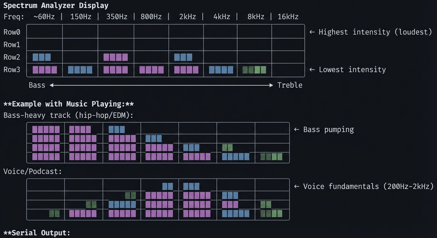 FFT Spectrum Analyzer
ADC configured: 44100 Hz sample rate
FFT size: 256 bins
Window function: Hanning
FFT Spectrum Analyzer
ADC configured: 44100 Hz sample rate
FFT size: 256 bins
Window function: Hanning
Frequency bins: Col 0: 0- 172 Hz (bass) Col 1: 172- 344 Hz Col 2: 344- 689 Hz Col 3: 689- 1378 Hz Col 4: 1378- 2756 Hz Col 5: 2756- 5512 Hz Col 6: 5512-11025 Hz Col 7: 11025-22050 Hz (treble)
Live readings (dB): Bass: -12dB | Lo-Mid: -18dB | Hi-Mid: -24dB | Treble: -36dB
---

##### Observable Behavior & Validation

- **FFT bars** respond instantly to bass/mids/treble changes.
- **Noise floor** remains low when input is silent.

Example serial output:

```text
[FFT] bin[3]=0.74 bin[10]=0.22 bin[40]=0.05
The Core Question You’re Answering
“How do you decompose a complex audio signal into its constituent frequencies, and why does this reveal the ‘content’ of sound?”
The Fourier Transform reveals a fundamental truth: any signal can be represented as a sum of sine waves at different frequencies and amplitudes. When you hear a chord, you’re hearing multiple frequencies simultaneously. The FFT decomposes this, showing you exactly which frequencies are present and how loud each is.
Concepts You Must Understand First
Stop and research these before coding:
- Fourier Transform Basics
- What does the Fourier Transform do mathematically?
- What’s the relationship between time domain and frequency domain?
- Why does a square wave contain odd harmonics?
- Book Reference: “Understanding DSP” Ch. 3
- FFT Mechanics
- Why is FFT faster than DFT? (O(N log N) vs O(N²))
- What’s the relationship between FFT size and frequency resolution?
- What happens if your FFT size is 256? (You get 128 useful frequency bins)
- Book Reference: “Understanding DSP” Ch. 4
- Windowing
- What’s spectral leakage and why does it happen?
- How does a Hanning window help? What about Blackman?
- What’s the tradeoff between frequency resolution and spectral leakage?
- Book Reference: “DSP First” Ch. 7
- Logarithmic Frequency Perception
- Why does each octave double in frequency? (C4=262Hz, C5=523Hz)
- Why should frequency bin mapping be logarithmic for display?
- What’s the mel scale?
Spec Anchor: FFT and analysis objects in the PJRC Audio ecosystem assume 16‑bit, 44.1 kHz streaming blocks. Source: https://www.pjrc.com/teensy/td_libs_Audio.html
Questions to Guide Your Design
Before implementing, think through these:
- FFT Configuration
- What FFT size? (Larger = better frequency resolution, worse time resolution)
- What window function? (Hanning is a good default)
- How often to compute FFT? (Every N samples = N/sample_rate seconds)
- Bin to Column Mapping
- 256-point FFT gives 128 bins (0-22050 Hz). How do you map to 8 columns?
- Linear mapping (16 bins per column) or logarithmic (more bass detail)?
- How do you average multiple bins into one column?
- Intensity to Row Mapping
- FFT output is magnitude (or magnitude squared). What’s a reasonable dB range?
- -60dB (quiet) to 0dB (loud)? How does that map to 4 rows?
- Should you use peak hold? Decay? Averaging?
Thinking Exercise
Calculate Frequency Bins
Before coding, work out the math:
Given:
- Sample rate: 44100 Hz
- FFT size: 256
- Useful bins: 128 (bins 0-127, the rest are mirror)

Frequency resolution:
- Each bin represents: 44100 / 256 = 172.27 Hz

Bin 0: 0 Hz (DC offset)
Bin 1: 172 Hz
Bin 2: 344 Hz
...
Bin 127: 21,879 Hz

Logarithmic mapping to 8 columns:
- Bass (0):    20 Hz -   80 Hz → bins 0-0   (but we skip DC)
- (1):        80 Hz -  300 Hz → bins 1-2
- (2):       300 Hz -  700 Hz → bins 2-4
- (3):       700 Hz - 1.5 kHz → bins 4-9
- (4):      1.5 kHz -   3 kHz → bins 9-17
- (5):        3 kHz -   6 kHz → bins 17-35
- (6):        6 kHz -  12 kHz → bins 35-70
- Treble (7): 12 kHz - 22 kHz → bins 70-127

For each column, average the magnitudes of all bins in that range.
Questions:
- Why is the bass range (20-80 Hz) only ~1 bin? (Frequency resolution limitation)
- How would you get better bass resolution? (Larger FFT size)
- What happens if you display raw magnitude instead of dB? (Bass overwhelms display)
The Interview Questions They’ll Ask
-
“Explain the relationship between FFT size, sample rate, and frequency resolution.”
-
“Why do you apply a window function before computing the FFT? What happens if you don’t?”
-
“Your spectrum analyzer shows significant energy at 0 Hz. What’s causing this and how do you fix it?”
-
“The display is flickering rapidly. How do you smooth the output while maintaining responsiveness?”
-
“How would you detect a specific note (like A4 = 440 Hz) from the FFT output?”
Hints in Layers
Hint 1: Starting Point
Use AudioAnalyzeFFT256 from the PJRC Audio library. It handles FFT computation internally. Call fft.read(bin_number) to get bin magnitudes (0.0 to 1.0).
Hint 2: Logarithmic Mapping
// Octave-based bands (each doubles in frequency)
int bandBins[8][2] = {
  {1, 2},    // ~60-300 Hz
  {2, 4},    // ~300-700 Hz
  {4, 8},    // ~700-1400 Hz
  {8, 16},   // ~1.4-2.8 kHz
  {16, 32},  // ~2.8-5.5 kHz
  {32, 64},  // ~5.5-11 kHz
  {64, 96},  // ~11-16 kHz
  {96, 128}  // ~16-22 kHz
};
Hint 3: dB Conversion
float magnitude = fft.read(bin);
float dB = 20 * log10(magnitude + 0.00001);  // Avoid log(0)
// Map -60dB...0dB to 0...4 rows
int row = map(dB, -60, 0, 0, 4);
Hint 4: Temporal Smoothing
// Exponential moving average
smoothed[col] = 0.8 * smoothed[col] + 0.2 * current[col];
Books That Will Help
| Topic | Book | Chapter |
|---|---|---|
| FFT fundamentals | “Understanding DSP” by Richard Lyons | Ch. 3-4 |
| Windowing | “DSP First” by McClellan et al. | Ch. 7 |
| Audio analysis | “The Audio Programming Book” | Ch. 6 |
| Spectral display | “Real-Time DSP” by Kuo & Gan | Ch. 5 |
Common Pitfalls & Debugging
| Problem | Cause | Fix | Verification |
|---|---|---|---|
| No signal | ADC not configured | Check AudioInputAnalog setup | Print raw ADC values |
| DC spike (bin 0 always high) | DC offset in signal | Remove DC bias or ignore bin 0 | Play pure tone, check bins |
| Spectral leakage | No windowing | Enable Hanning window | Compare with/without window |
| Display flickers | No smoothing | Add exponential average | Slow update rate, check |
| Bass always low | Linear bin mapping | Use logarithmic mapping | Play bass-heavy music |
Advanced Pitfalls
- FFT window mismatch causes spectral leakage.
- Overdriving input clips ADC and flattens bars.
Learning Milestones
- FFT output visible → You understand the audio graph
- Bins map to columns → You understand frequency resolution
- Logarithmic scaling works → You understand human hearing
- Display is smooth → You’ve implemented temporal filtering
- Reacts musically → You’ve tuned sensitivity and mapping
Project 9: Sample Player with Live Effects (Arduino)
- File: LEARN_NEOTRELLIS_M4_DEEP_DIVE.md
- Main Programming Language: Arduino C++
- Alternative Programming Languages: Bare-metal C with custom DSP
- Coolness Level: Level 4: Hardcore Tech Flex
- Business Potential: 3. The “Service & Support” Model
- Difficulty: Level 3: Advanced
- Knowledge Area: Audio Effects, Real-Time DSP, User Interface Design
- Software or Tool: Arduino IDE, PJRC Audio Library
- Main Book: “DAFX: Digital Audio Effects” edited by Udo Zölzer
What you’ll build: A sample player that loads audio clips from flash, triggers them with buttons, and applies real-time effects: delay, reverb, bitcrusher, and filter. Multiple effect parameters are controllable via button combinations and accelerometer.
Why it teaches audio effects processing: Digital audio effects are the foundation of modern music production. You’ll understand how delay lines work, what convolution reverb actually does, and how bit reduction creates “lo-fi” textures—all implemented in real-time.
Core challenges you’ll face:
- Sample loading → Loading WAV files from 8MB QSPI flash
- Delay implementation → Understanding circular buffers and delay lines
- Reverb basics → Multiple delay taps with feedback create space
- Bitcrusher → Sample rate and bit depth reduction for effect
- Parameter mapping → Intuitive control of multiple parameters
Key Concepts:
- Delay effects: “DAFX” Ch. 2 - Delay-based effects
- Reverb algorithms: “DAFX” Ch. 5 - Reverberation
- Distortion/bitcrush: “DAFX” Ch. 4 - Nonlinear processing
- Audio buffer management: Real-time DSP patterns
Difficulty: Advanced Time estimate: 2-3 weeks (20-30 hours) Prerequisites: Projects 6-7 completed
Real World Outcome
Your NeoTrellis becomes an effects-laden sampler:
                    Sample Player Layout

    ┌────┬────┬────┬────┬────┬────┬────┬────┐
Row0│ S1 │ S2 │ S3 │ S4 │ S5 │ S6 │ S7 │ S8 │ ← Sample triggers
    ├────┼────┼────┼────┼────┼────┼────┼────┤    (8 samples)
Row1│DEL+│DEL-│REV+│REV-│BIT+│BIT-│FLT+│FLT-│ ← Effect controls
    ├────┼────┼────┼────┼────┼────┼────┼────┤
Row2│SYNC│HALF│REV │CHOP│ LP │ HP │ BP │ BY │ ← Effect modes
    ├────┼────┼────┼────┼────┼────┼────┼────┤
Row3│ PAT1│PAT2│PAT3│PAT4│SAVE│LOAD│ << │ >> │ ← Pattern management
    └────┴────┴────┴────┴────┴────┴────┴────┘

**Effect Chain:**
    ┌────────┐   ┌────────┐   ┌────────┐   ┌────────┐   ┌────────┐
    │ Sample │──▶│ Filter │──▶│BitCrush│──▶│ Delay  │──▶│ Reverb │──▶ Out
    │ Player │   │ LP/HP  │   │        │   │ Sync   │   │        │
    └────────┘   └────────┘   └────────┘   └────────┘   └────────┘
                     ↑            ↑            ↑            ↑
                 Tilt Y       Button       Tempo       Tilt X

**Serial Output:**
Sample Player initialized Loaded 8 samples from QSPI flash: S1: kick.wav (4410 samples, 100ms) S2: snare.wav (6615 samples, 150ms) S3: chord.wav (44100 samples, 1000ms) S4: vocal.wav (88200 samples, 2000ms) …
Effect chain configured: [Filter] Mode: LowPass, Cutoff: 5000Hz, Resonance: 1.5 [BitCrush] Bits: 12, Sample Rate: 44100 (off) [Delay] Time: 250ms, Feedback: 40%, Mix: 30% [Reverb] Size: 0.7, Damping: 0.3, Mix: 20%
Playing S3 with effects: Filter sweeping (accelerometer Y) Delay synced to 125ms (120 BPM / 2) Reverb tail: 2.1 seconds
---

##### Observable Behavior & Validation

- **Sample triggers** are immediate with consistent volume.
- **Effects toggle** (reverb/low‑pass) changes tone without dropouts.

Example serial output:

```text
[SAMPLE] id=3 start=0ms length=420ms fx=LPF(1.2k)
The Core Question You’re Answering
“How do audio effects transform sound, and what are the fundamental building blocks of delay, reverb, and distortion?”
Most audio effects can be understood as combinations of basic operations: delay lines (storing past samples), feedback (mixing output back to input), filtering (changing frequency content), and nonlinear processing (waveshaping, clipping, quantization).
Concepts You Must Understand First
Stop and research these before coding:
- Delay Lines
- What is a circular buffer and why use it for audio?
- How does feedback create echoes?
- What’s the relationship between delay time and buffer size?
- Book Reference: “DAFX” Ch. 2
- Reverb Basics
- How do multiple delay taps create the impression of space?
- What’s the difference between early reflections and reverb tail?
- What does “damping” mean in reverb context?
- Book Reference: “DAFX” Ch. 5
- Bitcrushing
- What happens when you reduce bit depth? (Quantization noise)
- What happens when you reduce sample rate? (Aliasing)
- Why does this create “lo-fi” character?
- Book Reference: “DAFX” Ch. 4
- Filters in Audio
- How does a low-pass filter change timbre?
- What’s filter resonance and why does it create emphasis?
- How do you sweep a filter in real-time?
- Book Reference: “Introduction to Digital Filters” by Smith
Spec Anchor: Sample playback in the PJRC Audio ecosystem is optimized for 16‑bit, 44.1 kHz streams; plan memory and buffers accordingly. Source: https://www.pjrc.com/teensy/td_libs_Audio.html
Questions to Guide Your Design
Before implementing, think through these:
- Effect Order
- Does filter before delay sound different than delay before filter?
- Where should bitcrusher go? (Usually early—affects subsequent processing)
- Should reverb always be last? (Usually yes—reverb on dry signal)
- Control Mapping
- How do you make effect control intuitive?
- Should accelerometer control be global or per-effect?
- How do you indicate current effect settings visually?
- Real-Time Constraints
- Can you run all effects simultaneously without dropout?
- What’s the CPU budget for effects vs. LED updates?
- How do you prioritize if CPU is overloaded?
Thinking Exercise
Design a Delay Effect
Before coding, trace how a 250ms delay with 50% feedback works:
Sample rate: 44100 Hz
Delay time: 250ms
Buffer size: 44100 * 0.250 = 11025 samples

Time t=0: Input sample S0 arrives
  Buffer[0] = S0
  Output = S0 + Buffer[11025] (initially 0)

Time t=1/44100: Input sample S1
  Buffer[1] = S1
  Output = S1 + Buffer[11026]

...

Time t=250ms: Input sample S11025
  Buffer[11025] = S11025 + 0.5 * Output_from_250ms_ago
                = S11025 + 0.5 * S0
  Output = S11025 + Buffer[0]
         = S11025 + S0  (the delayed signal!)

Time t=500ms:
  Buffer[0] now contains S0 * 0.5 (feedback)
  Output includes S0 * 0.5 (second echo, quieter)

Decay pattern:
  0ms:   Original signal (100%)
  250ms: First echo (50%)
  500ms: Second echo (25%)
  750ms: Third echo (12.5%)
  ...
Questions:
- What feedback percentage creates infinite echo? (100%)
- What happens if feedback > 100%? (Runaway feedback, clipping)
- How do you sync delay time to BPM? (delay_ms = 60000 / BPM / subdivision)
The Interview Questions They’ll Ask
-
“Explain how a circular buffer implements a delay line. Show the read/write pointer relationship.”
-
“Your reverb sounds ‘metallic’. What’s causing this and how would you fix it?”
-
“How do you implement tempo-synced delay? What happens when tempo changes while delay is active?”
-
“The bitcrusher creates aliasing artifacts. Is this desirable? How would you eliminate them if not?”
-
“Your effects chain is using 95% CPU. How do you optimize without removing effects?”
Hints in Layers
Hint 1: Starting Point
Use AudioEffectDelay and AudioEffectReverb from PJRC library. They handle the DSP internally. Use AudioEffectBitcrusher for lo-fi effects (if available, or use AudioEffectWaveshaper for similar effect).
Hint 2: Delay Control
delay1.delay(0, delayTime);  // Channel 0, time in ms
// For feedback, route delay output back to input:
// mix -> delay -> mix (one channel is feedback path)
Hint 3: Filter Sweep
// Map accelerometer (-10 to +10) to frequency (100 to 10000)
float freq = map(accel_y * 100, -1000, 1000, 100, 10000);
filter1.frequency(freq);
filter1.resonance(2.0);  // Slight emphasis
Hint 4: CPU Monitoring
Serial.print("CPU: ");
Serial.print(AudioProcessorUsage());
Serial.println("%");
// If > 90%, effects may glitch
Books That Will Help
| Topic | Book | Chapter |
|---|---|---|
| Delay effects | “DAFX” edited by Zölzer | Ch. 2 |
| Reverb | “DAFX” | Ch. 5 |
| Distortion/crush | “DAFX” | Ch. 4 |
| Effect design | “Designing Audio Effect Plugins in C++” | Ch. 1-6 |
Common Pitfalls & Debugging
| Problem | Cause | Fix | Verification |
|---|---|---|---|
| Audio dropout | CPU overload | Reduce effect complexity | Check AudioProcessorUsage() |
| Metallic reverb | Feedback too high | Reduce reverb time or damping | Compare to commercial reverb |
| Delay runaway | Feedback ≥ 100% | Cap feedback at 95% max | Listen for escalating volume |
| Filter clicks | Sudden parameter change | Interpolate parameter changes | Slow down sweep, listen |
| Sample pops | Loading while playing | Double buffer sample loading | Pre-load all samples |
Advanced Pitfalls
- Sample start jitter when you allocate memory on trigger.
- Clicks at loop points without windowing or crossfade.
Learning Milestones
- Samples play cleanly → You understand audio playback
- One effect working → You understand audio routing
- Multiple effects chain → You’ve mastered audio graph connections
- Real-time control works → You’ve integrated sensors with effects
- Musical and playable → You’ve tuned parameters for usability
Project 10: Capacitive Touch Theremin (Arduino + Hardware Mod)
- File: LEARN_NEOTRELLIS_M4_DEEP_DIVE.md
- Main Programming Language: Arduino C++
- Alternative Programming Languages: Bare-metal C
- Coolness Level: Level 5: Pure Magic (Super Cool)
- Business Potential: 2. The “Micro-SaaS / Pro Tool”
- Difficulty: Level 3: Advanced
- Knowledge Area: Capacitive Sensing, Audio Synthesis, Human Interface
- Software or Tool: Arduino IDE, External wire/foil for antenna
- Main Book: “Making Embedded Systems” by Elecia White
What you’ll build: A theremin-style instrument using the NeoTrellis M4’s GPIO for capacitive sensing. Moving your hand near a wire “antenna” controls pitch; a second antenna controls volume. Visual feedback on LEDs shows the current note and amplitude. Pure audio synthesis creates the classic theremin warble.
Why it teaches capacitive sensing and continuous control: Buttons are binary (on/off), but capacitive sensing provides continuous analog input based on proximity. This project bridges discrete digital systems with continuous real-world interaction—a fundamental embedded systems skill.
Core challenges you’ll face:
- Capacitive sensing → Using GPIO and timing to detect hand proximity
- Calibration → Accounting for environmental variations
- Continuous pitch control → Mapping noisy sensor data to musical pitch
- Vibrato effect → The classic theremin sound requires subtle frequency modulation
- Latency minimization → Theremin requires near-zero latency for playability
Key Concepts:
- Capacitive touch sensing: RC timing measurement
- Analog-to-digital considerations: “Making Embedded Systems” Ch. 7
- Continuous controllers: “Designing Sound” - continuous input
- Theremin design: Historical instrument design
Difficulty: Advanced Time estimate: 2-3 weeks (20-30 hours) Prerequisites: Projects 6-7 completed, soldering skills for antenna attachment
Real World Outcome
Your NeoTrellis becomes a touchless musical instrument:
                    Theremin Setup

                      Pitch Antenna
                           │
                           │ (wire ~20cm)
                           │
    ┌──────────────────────┼─────────────────────────────────┐
    │                      │                                 │
    │  [NeoTrellis M4] ────┴──── GPIO Pin (with antenna)     │
    │                                                        │
    │        ●────────────────── Volume Antenna (optional)   │
    │                                                        │
    │  Hand approaches ──▶ Capacitance increases ──▶ Pitch ↑ │
    └────────────────────────────────────────────────────────┘


                    Visual Feedback Display

    ┌────┬────┬────┬────┬────┬────┬────┬────┐
Row0│ C  │ C# │ D  │ D# │ E  │ F  │ F# │ G  │ ← Current note indicator
    ├────┼────┼────┼────┼────┼────┼────┼────┤    (bright = current pitch)
Row1│ G# │ A  │ A# │ B  │ C  │ C# │ D  │ D# │
    ├────┼────┼────┼────┼────┼────┼────┼────┤
Row2│ ▓  │ ▓  │ ▓  │ ▓  │ ▓  │ ▓  │ ░  │    │ ← Volume meter
    ├────┼────┼────┼────┼────┼────┼────┼────┤
Row3│CAL │SCAL│OCT-│OCT+│VIB-│VIB+│HOLD│MUTE│ ← Controls
    └────┴────┴────┴────┴────┴────┴────┴────┘

**Serial Output:**
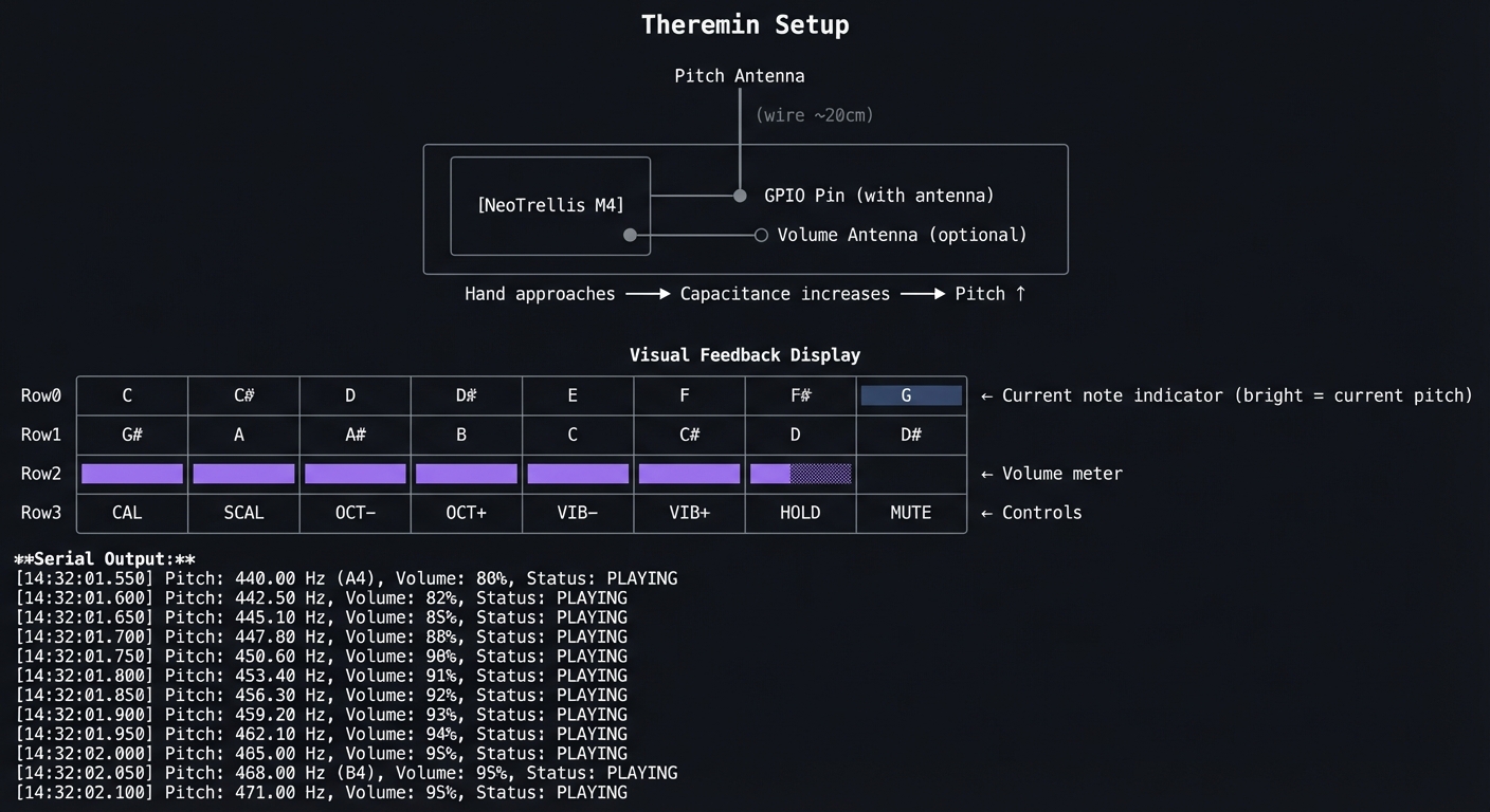 Theremin initialized
Capacitive sensing on GPIO A0 (pitch), A1 (volume)
Theremin initialized
Capacitive sensing on GPIO A0 (pitch), A1 (volume)
Calibrating… (remove hands from antennas) Baseline pitch: 1523 (raw count) Baseline volume: 1489 (raw count) Calibration complete.
Range: C3 (130.81 Hz) to C5 (523.25 Hz) Vibrato: Rate=5Hz, Depth=10 cents
Live readings: Raw pitch: 1687 → Distance: 12cm → Note: G4 (392 Hz) Raw volume: 1601 → Amplitude: 0.67 Output frequency: 392.0 Hz + vibrato
**Audio output**: Continuous, ethereal theremin tones through headphones.

---

##### Observable Behavior & Validation

- **Hand distance** shifts pitch smoothly over at least 1–2 octaves.
- **LED feedback** mirrors pitch or volume to help play in tune.

Example serial output:

```text
[THEREMIN] cap=187 baseline=120 freq=523.3Hz
The Core Question You’re Answering
“How can you detect proximity without physical contact, and how do you turn noisy analog measurements into precise musical pitch?”
Capacitive sensing exploits a fundamental physics principle: your body has capacitance. When you move your hand near a conductor, you change the capacitance of the system. By measuring how long it takes to charge/discharge that capacitance, you can detect proximity. The challenge is turning these noisy measurements into stable, musical pitch.
Concepts You Must Understand First
Stop and research these before coding:
- Capacitive Sensing Basics
- What is capacitance? (Ability to store charge)
- How does proximity change capacitance?
- What’s the RC time constant and why does it matter?
- Measurement Techniques
- How do you measure capacitance with a digital GPIO?
- What’s the “charge transfer” method?
- How does environmental noise affect readings?
- Calibration
- Why is baseline calibration necessary?
- What environmental factors affect capacitance? (Humidity, nearby objects)
- How do you recalibrate dynamically?
- Pitch Mapping
- Linear mapping vs logarithmic for pitch?
- How do you quantize to musical notes (if desired)?
- What’s “portamento” and how do you implement it?
Questions to Guide Your Design
Before implementing, think through these:
- Hardware Setup
- What GPIO pins can you use? (Check NeoTrellis M4 available pins)
- How long should the antenna wire be? (Longer = more sensitive but noisier)
- How do you isolate pitch and volume antennas?
- Signal Processing
- Raw readings will be noisy. How do you smooth them?
- How fast can you sample? (Speed vs noise tradeoff)
- What’s acceptable latency for theremin playing? (< 10ms ideal)
- Musical Design
- What pitch range? (2 octaves is typical)
- Continuous pitch or quantized to scale?
- How strong should vibrato be?
Thinking Exercise
Design the Sensing Circuit
Before coding, understand the measurement:
Capacitive Sensing via Charge Time

      VCC (3.3V)
       │
       R (1MΩ resistor)
       │
       ├───── GPIO Pin (measures voltage)
       │
       C (capacitance: your hand + antenna)
       │
      GND

Charge cycle:
1. Set pin to OUTPUT LOW (discharge C)
2. Set pin to INPUT (high impedance)
3. Wait for external pullup through R
4. Count time until pin reads HIGH

Time constant: τ = R × C
Time to reach ~63% of VCC: t = τ = R × C

Example:
  R = 1MΩ
  C (no hand) = 10pF → τ = 10μs
  C (hand near) = 50pF → τ = 50μs

By measuring the charge time, we measure capacitance,
which varies with hand proximity!
Questions:
- What happens if the resistor is too small? (Charges too fast to measure)
- What happens if too large? (Too slow, affects update rate)
- How do you handle readings that vary wildly? (Filtering)
The Interview Questions They’ll Ask
-
“Explain how you measure capacitance using only a digital GPIO pin.”
-
“Your theremin pitch is unstable. What filtering would you apply?”
-
“The readings drift over time. What’s causing this and how do you compensate?”
-
“How would you implement pitch quantization to a specific musical scale?”
-
“Compare capacitive sensing to other proximity detection methods (IR, ultrasonic). What are the tradeoffs?”
Hints in Layers
Hint 1: Starting Point
Use the Arduino CapacitiveSensor library or implement your own charge-time measurement. On SAMD51, use PTC (Peripheral Touch Controller) if available in your setup.
Hint 2: Basic Measurement
// Simple charge time measurement
long measureCapacitance(int pin) {
    long count = 0;
    pinMode(pin, OUTPUT);
    digitalWrite(pin, LOW);  // Discharge
    delayMicroseconds(10);
    pinMode(pin, INPUT);     // Let charge
    while (!digitalRead(pin) && count < 10000) {
        count++;
    }
    return count;
}
Hint 3: Filtering
// Running average over last N readings
#define N 8
long readings[N];
int index = 0;

long getFiltered(int pin) {
    readings[index] = measureCapacitance(pin);
    index = (index + 1) % N;
    long sum = 0;
    for (int i = 0; i < N; i++) sum += readings[i];
    return sum / N;
}
Hint 4: Pitch Mapping
// Map filtered reading to frequency
float baseline = 1500;  // Calibrated
float maxReading = 3000;  // Hand touching
float minFreq = 130.81;   // C3
float maxFreq = 523.25;   // C5

float freq = map(filtered, baseline, maxReading, minFreq, maxFreq);
freq = constrain(freq, minFreq, maxFreq);
Books That Will Help
| Topic | Book | Chapter |
|---|---|---|
| Capacitive sensing | “Making Embedded Systems” by White | Ch. 7 |
| Sensor interfacing | “Sensors and Signal Conditioning” | Ch. 5 |
| Theremin design | “Electronic Music” by Collins | Ch. 8 |
| Audio synthesis | “The Audio Programming Book” | Ch. 1-2 |
Common Pitfalls & Debugging
| Problem | Cause | Fix | Verification |
|---|---|---|---|
| No change with hand | Antenna too short | Use longer wire (15-30cm) | Print raw readings |
| Very noisy readings | EMI interference | Add shielding, better grounding | Look at reading variance |
| Readings drift | Temperature/humidity change | Implement auto-calibration | Track baseline over time |
| Pitch jumps | Insufficient filtering | Increase filter window | Graph filtered readings |
| High latency | Filter too aggressive | Reduce filter window | Measure response time |
Advanced Pitfalls
- Cap sensor drift due to humidity or grounding.
- Baseline not recalibrated after warm‑up leads to pitch drift.
Learning Milestones
- Raw capacitance readings vary with hand → Hardware works
- Filtered readings are stable → Signal processing works
- Pitch tracks hand smoothly → Mapping and calibration work
- Audio output sounds like theremin → Synthesis and vibrato work
- Playable musical instrument → Full system integration complete
Bare-Metal C Programming Projects (11-15)
These projects remove all abstractions (CircuitPython, Arduino) and work directly with the SAMD51 hardware. You’ll write your own startup code, linker scripts, and register-level drivers.
Project 11: Bare-Metal LED Blinker (Pure C)
- File: LEARN_NEOTRELLIS_M4_DEEP_DIVE.md
- Main Programming Language: C (bare-metal)
- Alternative Programming Languages: Assembly (ARM)
- Coolness Level: Level 4: Hardcore Tech Flex
- Business Potential: 1. The “Resume Gold”
- Difficulty: Level 4: Expert
- Knowledge Area: ARM Architecture, Linker Scripts, Startup Code, GPIO Registers
- Software or Tool: arm-none-eabi-gcc, OpenOCD, BOSSA
- Main Book: “Bare Metal C” by Steve Oualline
What you’ll build: A completely from-scratch LED blinker—no libraries, no Arduino, no runtime. You’ll write the startup code, linker script, and directly manipulate the PORT registers to toggle the NeoPixel data pin. This is the “Hello World” of bare-metal embedded development.
Why it teaches embedded fundamentals: This project strips away every abstraction. You’ll understand what happens between power-on and main(), how the linker places code in flash, and what a “register” actually is at the memory address level.
Core challenges you’ll face:
- Toolchain setup → Installing and configuring arm-none-eabi-gcc
- Startup code → Initializing .data and .bss sections, setting up stack
- Linker script → Placing vector table, code, and data at correct addresses
- Clock configuration → Enabling and configuring the 120 MHz main clock
- GPIO configuration → Setting pin direction, output value via PORT registers
Key Concepts:
- ARM Cortex-M startup: “Bare Metal C” Ch. 3-4 - Oualline
- Linker scripts: “Bare Metal C” Ch. 6 - Oualline
- SAMD51 registers: SAMD51 Datasheet - PORT chapter
- Memory map: “Computer Systems: A Programmer’s Perspective” Ch. 7
Difficulty: Expert Time estimate: 2 weeks (15-25 hours) Prerequisites: Strong C programming, understanding of compilation/linking, Projects 1-10 completed
Real World Outcome
You’ll have a completely standalone binary that runs on the SAMD51:
                    Bare-Metal Project Structure

    project/
    ├── Makefile                    # Build rules
    ├── linker.ld                   # Memory layout
    ├── startup.c                   # Vector table, initialization
    ├── main.c                      # Your application (LED blink)
    └── samd51.h                    # Register definitions

**Build Output:**
```bash
$ make
arm-none-eabi-gcc -mcpu=cortex-m4 -mthumb -c -o startup.o startup.c
arm-none-eabi-gcc -mcpu=cortex-m4 -mthumb -c -o main.o main.c
arm-none-eabi-gcc -T linker.ld -nostdlib -nostartfiles -o firmware.elf startup.o main.o
arm-none-eabi-objcopy -O binary firmware.elf firmware.bin

Memory usage:
  text: 512 bytes
  data: 0 bytes
  bss:  4 bytes
  Total flash: 512 bytes (0.1% of 512KB)

$ bossac -p /dev/ttyACM0 -e -w -v firmware.bin
Erase flash
Write 512 bytes to flash
Verify 512 bytes in flash
Done!
Observed Result: The NeoPixel data pin (PA10 on SAMD51) toggles every ~500ms. Connect an oscilloscope or LED to verify:
- Pin HIGH for 500ms
- Pin LOW for 500ms
- Repeat forever
No serial output (we haven’t implemented UART yet!)—but the hardware proves the code works.
Observable Behavior & Validation
- GPIO toggles at a fixed period (e.g., 1 kHz) with minimal jitter.
- Logic analyzer shows a clean square wave at the expected frequency.
Example serial output:
[BLINK] period_us=1000 jitter_us=2
The Core Question You’re Answering
“What EXACTLY happens between power-on and when my
main()function starts executing?”
When you press the reset button:
- CPU loads initial stack pointer from address 0x00000000
- CPU loads reset vector from address 0x00000004
- CPU jumps to reset handler
- Reset handler initializes .data, clears .bss, sets up clocks
- Reset handler calls
main()
Without startup code, there IS no main()—just undefined behavior.
Concepts You Must Understand First
Stop and research these before coding:
- Vector Table
- What is the vector table and where must it be located?
- What are the first two entries? (Initial SP, Reset handler)
- How does the CPU find interrupt handlers?
- Book Reference: “The Definitive Guide to ARM Cortex-M4” Ch. 3
- Linker Script Basics
- What are MEMORY and SECTIONS commands?
- What’s the difference between VMA (Virtual Memory Address) and LMA (Load Memory Address)?
- Why does .data need to be copied from flash to RAM?
- Book Reference: “Bare Metal C” Ch. 6
- Startup Code
- Why must .bss be zeroed? (C standard says uninitialized globals = 0)
- Why must .data be copied from flash to RAM?
- What’s the difference between bss_start and bss_end?
- Book Reference: “Bare Metal C” Ch. 4
- SAMD51 Clock System
- What clock sources are available? (DFLL, DPLL, XOSC)
- What’s the default clock after reset?
- How do you configure GCLK (Generic Clock Controller)?
- Book Reference: SAMD51 Datasheet Ch. 14-16
Questions to Guide Your Design
Before implementing, think through these:
- Memory Layout
- Where does flash start? (0x00000000)
- Where does RAM start? (0x20000000)
- How big is flash? (512KB) How big is RAM? (192KB)
- Where should you put the stack? (End of RAM, growing down)
- Startup Sequence
- What happens if you try to use a global variable before .data is copied?
- What happens if you call a function that uses the stack before SP is set?
- In what order must you initialize things?
- GPIO Access
- What’s the base address of the PORT peripheral?
- What registers control pin direction (DIRSET) and output value (OUTSET/OUTCLR)?
- How do you specify “pin 10 of port A” in register terms?
Thinking Exercise
Trace the Boot Sequence
Before coding, trace what happens at power-on:
Power-on (or reset):

1. CPU reads address 0x00000000 (first 4 bytes of flash)
   → This contains the initial stack pointer value
   → CPU loads this into SP register
   → Typically points to end of RAM: 0x20030000

2. CPU reads address 0x00000004 (next 4 bytes of flash)
   → This contains the reset handler address
   → CPU loads this into PC (Program Counter)
   → This is the address of your Reset_Handler function

3. CPU begins executing at Reset_Handler:
   Reset_Handler:
     // Copy .data from flash to RAM
     src = &__data_load__;  // In flash (LMA)
     dst = &__data_start__; // In RAM (VMA)
     while (dst < &__data_end__) {
       *dst++ = *src++;
     }

     // Zero .bss
     dst = &__bss_start__;
     while (dst < &__bss_end__) {
       *dst++ = 0;
     }

     // (Optional) Configure clocks

     // Call main
     main();

     // If main returns, hang
     while(1);

4. main() starts executing
   → At this point, global variables work correctly
   → Stack is set up
   → Clocks are at default speed (unless you configured them)
Questions:
- What if you put the wrong value at address 0x00000000?
- What if Reset_Handler doesn’t copy .data—what variables would be wrong?
- Why does Reset_Handler need to be in the vector table, not just in code?
The Interview Questions They’ll Ask
-
“Explain what happens from CPU reset to the first line of main(). Be specific about memory addresses.”
-
“Your linker script has .data with different VMA and LMA. What does this mean and why is it necessary?”
-
“You wrote a bare-metal project and global variables have garbage values. What went wrong?”
-
“How would you add interrupt handling to your bare-metal project? Where does the handler address go?”
-
“Compare the binary size of your bare-metal blinker to an Arduino Blink sketch. Why is yours smaller?”
Hints in Layers
Hint 1: Starting Point Download the SAMD51 header files from Microchip (or use the ones from ASF/START). These define register addresses. Your linker script needs MEMORY sections for FLASH and RAM.
Hint 2: Minimal Linker Script
MEMORY
{
  FLASH (rx) : ORIGIN = 0x00000000, LENGTH = 512K
  RAM (rwx)  : ORIGIN = 0x20000000, LENGTH = 192K
}

SECTIONS
{
  .text : { *(.vectors) *(.text*) } > FLASH
  .data : { *(.data*) } > RAM AT > FLASH
  .bss : { *(.bss*) } > RAM
}
Hint 3: Minimal Vector Table
extern void Reset_Handler(void);
extern unsigned long _estack;

__attribute__((section(".vectors")))
void (*const vectors[])(void) = {
  (void (*)(void))&_estack,  // Initial SP
  Reset_Handler,              // Reset
  // ... other handlers (can be 0 for now)
};
Hint 4: GPIO Toggle
#define PORT_BASE 0x41008000
#define PORT_DIRSET (*(volatile uint32_t *)(PORT_BASE + 0x08))
#define PORT_OUTTGL (*(volatile uint32_t *)(PORT_BASE + 0x1C))

// Set PA10 as output
PORT_DIRSET = (1 << 10);

// Toggle PA10
PORT_OUTTGL = (1 << 10);
Books That Will Help
| Topic | Book | Chapter |
|---|---|---|
| Bare-metal C | “Bare Metal C” by Steve Oualline | Ch. 1-6 |
| ARM startup | “The Definitive Guide to ARM Cortex-M4” by Yiu | Ch. 3-4 |
| Linker scripts | “Linker and Loaders” by Levine | Ch. 3-4 |
| SAMD51 specifics | SAMD51 Datasheet | PORT, GCLK chapters |
Common Pitfalls & Debugging
| Problem | Cause | Fix | Verification | |
|---|---|---|---|---|
| Code doesn’t run | Vector table not at 0x0 | Check linker script .vectors section | hexdump -C firmware.bin | head |
| Global variables wrong | .data not copied | Implement startup copy loop | Print variable values (need UART) | |
| Random crashes | .bss not zeroed | Implement startup zero loop | Static analysis | |
| No toggle observed | Wrong pin or register | Check datasheet, verify with scope | Use debugger | |
| Build fails | Missing toolchain | Install arm-none-eabi-gcc | arm-none-eabi-gcc –version |
Advanced Pitfalls
- Writing wrong register due to missing peripheral clock enable.
- Non‑volatile pointer causes optimizer to remove the write.
Learning Milestones
- Toolchain works → You can compile for ARM Cortex-M4
- Binary flashes → Linker script places code correctly
- Code executes → Startup code reaches main()
- Pin toggles → You understand GPIO registers
- Correct timing → You’ve implemented delay (even busy-wait)
Project 12: Bare-Metal NeoPixel Driver (Pure C)
- File: LEARN_NEOTRELLIS_M4_DEEP_DIVE.md
- Main Programming Language: C (bare-metal)
- Alternative Programming Languages: Assembly for timing-critical parts
- Coolness Level: Level 5: Pure Magic (Super Cool)
- Business Potential: 1. The “Resume Gold”
- Difficulty: Level 5: Master
- Knowledge Area: DMA, SERCOM/SPI, Bit-Banging, Real-Time Constraints
- Software or Tool: arm-none-eabi-gcc, Logic analyzer recommended
- Main Book: “The Definitive Guide to ARM Cortex-M4” by Joseph Yiu
What you’ll build: A complete NeoPixel driver from scratch—no libraries. You’ll implement the precise timing protocol (350ns/700ns pulses) using either bit-banging with cycle counting, or SPI/SERCOM peripheral + DMA for efficient transfers.
Why it teaches real-time embedded constraints: NeoPixels require sub-microsecond timing precision. This project forces you to count CPU cycles, understand peripheral configuration, and potentially use DMA to offload timing-critical work from the CPU.
Core challenges you’ll face:
- Timing precision → Generating 350ns and 700ns pulses at 120MHz
- Peripheral configuration → Setting up SERCOM as SPI master
- DMA setup → Configuring DMA to feed SPI automatically
- Double buffering → Updating LED data while previous frame transmits
- Interrupt handling → Knowing when transfer completes
Key Concepts:
- NeoPixel protocol: WS2812B datasheet - timing requirements
- SERCOM/SPI: SAMD51 Datasheet - SERCOM chapter
- DMA controller: SAMD51 Datasheet - DMAC chapter
- Cycle counting: ARM instruction timing
Difficulty: Master Time estimate: 3-4 weeks (25-40 hours) Prerequisites: Project 11 completed, understanding of SPI protocol
Real World Outcome
You control all 32 NeoPixels with pure C code you wrote:
                    NeoPixel Driver Architecture

    ┌─────────────────────────────────────────────────────────────────┐
    │                       Your Code                                 │
    │                                                                 │
    │   uint8_t framebuffer[32 * 3];  // 32 LEDs × 3 bytes (GRB)     │
    │                                                                 │
    │   // Set LED 5 to red                                          │
    │   framebuffer[5*3 + 0] = 0;      // Green                      │
    │   framebuffer[5*3 + 1] = 255;    // Red                        │
    │   framebuffer[5*3 + 2] = 0;      // Blue                       │
    │                                                                 │
    │   neopixel_show(framebuffer);    // Trigger DMA transfer        │
    └─────────────────────────┬───────────────────────────────────────┘
                              │
                              ▼
    ┌─────────────────────────────────────────────────────────────────┐
    │                      DMA Controller                             │
    │                                                                 │
    │   Source: framebuffer (RAM)                                     │
    │   Destination: SERCOM_SPI->DATA register                        │
    │   Count: 32 * 3 * 8 = 768 bytes (bit-expanded)                 │
    │   Trigger: SERCOM TX empty                                      │
    └─────────────────────────┬───────────────────────────────────────┘
                              │
                              ▼
    ┌─────────────────────────────────────────────────────────────────┐
    │                     SERCOM (SPI Mode)                           │
    │                                                                 │
    │   Clock: 2.4 MHz (to match NeoPixel timing)                    │
    │   MOSI: PA10 (NeoPixel data pin)                               │
    │   Encoding: Each NeoPixel bit = 3 SPI bits                     │
    │   "0" bit = 0b100 (high-low-low)                               │
    │   "1" bit = 0b110 (high-high-low)                              │
    └─────────────────────────┬───────────────────────────────────────┘
                              │
                              ▼
    ┌─────────────────────────────────────────────────────────────────┐
    │                     NeoPixel Chain                              │
    │                                                                 │
    │   → LED0 → LED1 → LED2 → ... → LED31 →                         │
    │                                                                 │
    │   Each LED grabs first 24 bits, passes rest to next            │
    └─────────────────────────────────────────────────────────────────┘

**Serial Output (via UART you implement in Project 13):**
![]() NeoPixel driver initialized
SPI clock: 2.4 MHz
DMA channel: 0
Bytes per frame: 768 (32 LEDs × 24 bits × 3 SPI bits / 8)
NeoPixel driver initialized
SPI clock: 2.4 MHz
DMA channel: 0
Bytes per frame: 768 (32 LEDs × 24 bits × 3 SPI bits / 8)
Frame 0: All red Frame 1: All green Frame 2: All blue Frame 3: Rainbow pattern … FPS: 60 (16.7ms per frame) DMA transfer time: 320μs CPU usage during transfer: 0% (DMA handles it!)
---

##### Observable Behavior & Validation

- **Data line** shows stable 800 kHz waveform, correct duty cycle.
- **Full frame** renders without flicker even at high brightness.

Example serial output:

```text
[NEO] frame_us=960 latch_us=300
The Core Question You’re Answering
“How do you generate precise sub-microsecond timing signals without consuming 100% CPU?”
The brute-force approach (bit-banging with delays) works but blocks the CPU entirely. The elegant solution uses SPI hardware to generate the timing, with DMA to feed data automatically. Your CPU is free to compute the next frame while hardware sends the current one.
Concepts You Must Understand First
Stop and research these before coding:
- NeoPixel Timing
- A “0” bit is HIGH for 350ns, LOW for 800ns
- A “1” bit is HIGH for 700ns, LOW for 600ns
- Total bit time: ~1.25μs
- Reset: LOW for > 50μs between frames
- SPI Trick for NeoPixels
- SPI outputs bits at fixed rate
- Encode each NeoPixel bit as 3 SPI bits
- At 2.4MHz SPI, each SPI bit = 417ns
- “0” = 0b100 = HIGH-LOW-LOW ≈ 417ns-834ns ✓
- “1” = 0b110 = HIGH-HIGH-LOW ≈ 834ns-417ns ✓
- SERCOM Configuration
- SERCOM can be I2C, SPI, or UART
- Must configure CTRLA, CTRLB, BAUD registers
- Pin mux must route SERCOM to correct GPIO
- DMA Basics
- DMA moves data without CPU involvement
- Source: RAM address (your framebuffer)
- Destination: peripheral register (SPI data)
- Trigger: peripheral “ready for data” signal
Spec Anchor: WS2812/NeoPixel data uses GRB byte order and requires a >300 μs low reset (latch) after each full frame. Source: https://learn.adafruit.com/adafruit-neopixel-uberguide
Questions to Guide Your Design
Before implementing, think through these:
- Encoding Strategy
- 24 bits per LED × 3 SPI bits per NeoPixel bit = 72 SPI bits = 9 bytes per LED
- 32 LEDs = 288 bytes transmitted per frame
- Do you pre-encode or encode on-the-fly?
- DMA vs Bit-Bang
- Bit-banging: CPU blocked for entire frame transmission
- DMA: CPU free during transmission
- What’s the frame transmission time? (32 × 24 × 1.25μs = ~960μs)
- Double Buffering
- If CPU modifies framebuffer during DMA, corruption occurs
- Solution: two buffers, swap after DMA complete
- How do you know DMA is done? (Interrupt or poll status)
Thinking Exercise
Calculate the SPI Encoding
Before coding, work out the bit encoding:
NeoPixel "0" bit: 350ns HIGH, 800ns LOW (total 1150ns)
NeoPixel "1" bit: 700ns HIGH, 600ns LOW (total 1300ns)
WS2812B tolerance: ±150ns

SPI approach:
  3 SPI bits per NeoPixel bit
  Target total: ~1250ns per NeoPixel bit
  SPI bit time: 1250ns / 3 = 417ns
  SPI frequency: 1 / 417ns = 2.4 MHz

Encoding:
  NeoPixel "0" = SPI 0b100
    HIGH: 417ns (within 350±150 = 200-500ns ✓)
    LOW:  834ns (within 800±150 = 650-950ns ✓)

  NeoPixel "1" = SPI 0b110
    HIGH: 834ns (within 700±150 = 550-850ns ✓)
    LOW:  417ns (within 600±150 = 450-750ns ✓)

Example: Send green=0x00, red=0xFF, blue=0x00 to LED 0:
  Green 0x00 = 0b00000000
  Encoded: 100 100 100 100 100 100 100 100 = 0x924924 (3 bytes)

  Red 0xFF = 0b11111111
  Encoded: 110 110 110 110 110 110 110 110 = 0xDB6DB6 (3 bytes)

  Blue 0x00 = 0b00000000
  Encoded: same as green = 0x924924 (3 bytes)

Total 9 bytes transmitted for one LED.
Questions:
- Why GRB order instead of RGB? (WS2812B specification)
- What happens if SPI clock is slightly off? (Timing errors, flickering)
- How do you generate the reset pulse? (Stop SPI, wait > 50μs)
The Interview Questions They’ll Ask
-
“Explain the SPI encoding trick for NeoPixels. Why does it work?”
-
“Your NeoPixel driver flickers occasionally. What could cause this?”
-
“Compare bit-banging vs SPI+DMA for NeoPixels. What are the tradeoffs?”
-
“How do you ensure the CPU can update the framebuffer while DMA is sending the previous frame?”
-
“What happens if an interrupt fires during bit-banged NeoPixel transmission?”
Hints in Layers
Hint 1: Starting Point First get SPI transmitting anything (verify with oscilloscope). Then work on encoding. Then add DMA.
Hint 2: SERCOM Configuration
// Enable SERCOM clock
MCLK->APBDMASK.bit.SERCOMx_ = 1;
GCLK->PCHCTRL[SERCOMx_GCLK_ID_CORE].reg = GCLK_PCHCTRL_GEN_GCLK0 | GCLK_PCHCTRL_CHEN;

// Configure SPI
SERCOMx->SPI.CTRLA.reg = SERCOM_SPI_CTRLA_MODE_SPI_MASTER |
                         SERCOM_SPI_CTRLA_DOPO(0);
SERCOMx->SPI.CTRLB.reg = SERCOM_SPI_CTRLB_RXEN;  // Enable receiver for status
SERCOMx->SPI.BAUD.reg = (F_CPU / (2 * 2400000)) - 1;  // 2.4 MHz
SERCOMx->SPI.CTRLA.bit.ENABLE = 1;
Hint 3: DMA Setup
// Configure DMA descriptor
descriptor.BTCTRL.reg = DMAC_BTCTRL_VALID | DMAC_BTCTRL_BEATSIZE_BYTE |
                        DMAC_BTCTRL_SRCINC | DMAC_BTCTRL_BLOCKACT_NOACT;
descriptor.BTCNT.reg = 288;  // Bytes to transfer
descriptor.SRCADDR.reg = (uint32_t)&encoded_buffer[288];  // End of source
descriptor.DSTADDR.reg = (uint32_t)&SERCOMx->SPI.DATA.reg;
Hint 4: Pre-encode Lookup Table
// Precompute all 256 byte encodings
// Each input byte becomes 3 output bytes
uint8_t encode_table[256][3];
// Or compute on-the-fly using bit manipulation
Books That Will Help
| Topic | Book | Chapter |
|---|---|---|
| DMA fundamentals | “The Definitive Guide to ARM Cortex-M4” | Ch. 12 |
| SERCOM details | SAMD51 Datasheet | SERCOM chapter |
| Real-time constraints | “Making Embedded Systems” by White | Ch. 8 |
| WS2812B protocol | WS2812B Datasheet | Timing specs |
Common Pitfalls & Debugging
| Problem | Cause | Fix | Verification |
|---|---|---|---|
| No output | Pin mux wrong | Check PMUX register | Scope on MOSI pin |
| Wrong colors | GRB vs RGB | Check byte order | Send pure red, verify |
| Flickering | Timing off | Adjust SPI baud | Measure with logic analyzer |
| First LED wrong | Reset timing | Ensure > 50μs gap | Time gap with scope |
| DMA doesn’t start | Trigger not configured | Check CHCTRLA.TRIGSRC | Poll DMA status |
Advanced Pitfalls
- Timing skew if interrupts fire mid‑bit.
- Latch time too short yields random color updates.
Learning Milestones
- SPI transmits → You understand SERCOM configuration
- Correct encoding → You understand the timing protocol
- Single LED works → End-to-end data path verified
- All 32 LEDs work → Full frame transmission working
- DMA transfers → CPU offloading achieved
Project 13: Bare-Metal UART Console (Pure C)
- File: LEARN_NEOTRELLIS_M4_DEEP_DIVE.md
- Main Programming Language: C (bare-metal)
- Alternative Programming Languages: None (C is ideal)
- Coolness Level: Level 3: Genuinely Clever
- Business Potential: 1. The “Resume Gold”
- Difficulty: Level 4: Expert
- Knowledge Area: UART Protocol, SERCOM, Ring Buffers, Printf Implementation
- Software or Tool: arm-none-eabi-gcc, USB-Serial adapter or native USB CDC
- Main Book: “Bare Metal C” by Steve Oualline
What you’ll build: A complete UART driver with transmit/receive, interrupt handling, and a minimal printf implementation. This gives you debugging capability for all future bare-metal projects.
Why it teaches serial communication: UART is the simplest communication protocol—no clock line, just TX and RX. Understanding it thoroughly prepares you for more complex protocols and gives you essential debugging capability.
Core challenges you’ll face:
- Baud rate calculation → Setting BAUD register for exact timing
- SERCOM as UART → Different configuration than SPI mode
- Interrupt-driven receive → Non-blocking character reception
- Ring buffer implementation → Efficient producer-consumer queue
- Printf implementation → Variadic functions and string formatting
Key Concepts:
- UART protocol: Start bit, data bits, stop bit
- SERCOM UART mode: SAMD51 Datasheet - SERCOM chapter
- Ring buffers: “Algorithms in C” - circular queue
- Variadic functions: C stdarg.h
Difficulty: Expert Time estimate: 2 weeks (15-20 hours) Prerequisites: Project 11 completed
Real World Outcome
You have printf-style debugging for all bare-metal projects:
                    UART Driver Architecture

    ┌─────────────────────────────────────────────────────────────────┐
    │                      Application Code                           │
    │                                                                 │
    │   uart_printf("LED %d: R=%d G=%d B=%d\n", led, r, g, b);       │
    │                                                                 │
    │   while (1) {                                                   │
    │     if (uart_available()) {                                    │
    │       char c = uart_getc();                                    │
    │       // Process command                                        │
    │     }                                                           │
    │   }                                                             │
    └─────────────────────────┬───────────────────────────────────────┘
                              │
                              ▼
    ┌─────────────────────────────────────────────────────────────────┐
    │                     UART Driver Layer                           │
    │                                                                 │
    │   TX Ring Buffer     ┌──────────┐     RX Ring Buffer           │
    │   [  |  |  |  |  ]◄──│ SERCOM   │──►[  |  |  |  |  ]          │
    │     ▲                │  UART    │                ▲              │
    │     │                │  Mode    │                │              │
    │   uart_putc()        └──────────┘           RX Interrupt        │
    │                           │                                     │
    │                           ▼                                     │
    │                      TX/RX Pins                                 │
    └─────────────────────────────────────────────────────────────────┘

**Terminal Output:**
=== NeoTrellis M4 Bare-Metal Console === Clock: 120 MHz UART: 115200 baud, 8N1
help Available commands: led
- Set LED color adc - Read accelerometer mem - Dump memory reset - Software reset
led 0 255 0 0 LED 0 set to R=255 G=0 B=0
adc X: -0.05g Y: 0.02g Z: 0.98g
mem 0x41008000 0x41008000: 00 00 00 00 00 04 00 00 00 00 00 00 00 00 00 00 (PORT peripheral base) ```
Observable Behavior & Validation
- Console echoes every character and handles backspace.
- No dropped bytes at the target baud rate.
Example serial output:
> help
Commands: led, tempo, status
The Core Question You’re Answering
“How does asynchronous serial communication work without a clock signal, and how do you build a reliable driver with buffering?”
UART works because both sides agree on timing (baud rate). The start bit signals “data coming”—the receiver samples at precise intervals to read each bit. Without careful timing, bits are misread.
Concepts You Must Understand First
Stop and research these before coding:
- UART Frame Format
- What’s a start bit? (Transition from IDLE to LOW)
- What’s a stop bit? (Return to IDLE)
- What does “8N1” mean? (8 data, No parity, 1 stop)
- Baud Rate
- What’s the relationship between baud rate and bit timing?
- At 115200 baud, how long is each bit? (1/115200 = 8.68μs)
- How do you calculate the BAUD register value?
- Ring Buffers
- Why use a ring buffer instead of blocking I/O?
- How do head and tail pointers work?
- What happens when the buffer is full?
- Printf Implementation
- What are variadic functions? (va_list, va_start, va_arg, va_end)
- How do you parse a format string?
- How do you convert integers to strings?
Questions to Guide Your Design
Before implementing, think through these:
- Buffer Sizing
- How big should TX and RX buffers be?
- What happens if TX buffer fills? (Block? Drop? Error?)
- What happens if RX buffer fills? (Overrun error)
- Interrupt vs Polling
- Polling:
while (!uart_rx_ready()) {}— wastes CPU - Interrupts: CPU notified when data arrives
- Which for TX? Which for RX?
- Polling:
- Printf Complexity
- Full printf is complex (%d, %x, %f, %s, %p, width, precision, flags)
- Minimal printf: just %d, %x, %s, %c?
- How much code size is acceptable?
Thinking Exercise
Design the Ring Buffer
Before coding, trace operations:
Buffer size: 8 (indices 0-7)
Initially: head=0, tail=0, empty

Operation: put('A')
  buffer[head] = 'A'
  head = (head + 1) % 8 = 1
  State: buffer=[A,_,_,_,_,_,_,_], head=1, tail=0

Operation: put('B')
  buffer[1] = 'B'
  head = 2
  State: buffer=[A,B,_,_,_,_,_,_], head=2, tail=0

Operation: get() → returns 'A'
  c = buffer[tail] = buffer[0] = 'A'
  tail = (tail + 1) % 8 = 1
  State: buffer=[_,B,_,_,_,_,_,_], head=2, tail=1

Operation: put('C'), put('D'), put('E'), put('F'), put('G'), put('H')
  State: buffer=[_,B,C,D,E,F,G,H], head=0, tail=1
  (head wrapped around!)

Operation: put('I')
  Check: (head + 1) % 8 == tail?  → 1 == 1? YES!
  Buffer is FULL! Cannot put.
  (We sacrifice one slot to distinguish full from empty)

is_empty: head == tail
is_full:  (head + 1) % size == tail
count:    (head - tail + size) % size
Questions:
- Why does the “one slot sacrificed” approach work?
- What’s the alternative? (Keep a count variable)
- How do you make this interrupt-safe? (Atomic operations or critical sections)
The Interview Questions They’ll Ask
-
“Explain the UART frame format. How does the receiver know when data starts?”
-
“Your UART is receiving garbage. What are the likely causes?”
-
“Implement a ring buffer. How do you handle the full and empty cases?”
-
“Your printf uses too much stack. How would you reduce it?”
-
“How do you make your ring buffer interrupt-safe?”
Hints in Layers
Hint 1: Starting Point Get TX working first (polling). Then RX (polling). Then add interrupts. Then ring buffers. Then printf.
Hint 2: SERCOM UART Configuration
// UART mode
SERCOMx->USART.CTRLA.reg = SERCOM_USART_CTRLA_MODE_USART_INT_CLK |
                           SERCOM_USART_CTRLA_RXPO(1) |  // RX on PAD1
                           SERCOM_USART_CTRLA_TXPO(0);   // TX on PAD0

// 8N1
SERCOMx->USART.CTRLB.reg = SERCOM_USART_CTRLB_TXEN | SERCOM_USART_CTRLB_RXEN;

// Baud = 115200
// BAUD = 65536 * (1 - 16 * (115200 / F_CPU))
Hint 3: Minimal Printf
void uart_printf(const char* fmt, ...) {
  va_list args;
  va_start(args, fmt);
  while (*fmt) {
    if (*fmt == '%') {
      fmt++;
      switch (*fmt) {
        case 'd': print_int(va_arg(args, int)); break;
        case 's': print_str(va_arg(args, char*)); break;
        // ... etc
      }
    } else {
      uart_putc(*fmt);
    }
    fmt++;
  }
  va_end(args);
}
Hint 4: Interrupt Handler
void SERCOMx_Handler(void) {
  if (SERCOMx->USART.INTFLAG.bit.RXC) {
    char c = SERCOMx->USART.DATA.reg;
    ring_buffer_put(&rx_buffer, c);
  }
}
Books That Will Help
| Topic | Book | Chapter |
|---|---|---|
| UART protocol | “Making Embedded Systems” by White | Ch. 7 |
| Ring buffers | “Algorithms in C” by Sedgewick | Ch. 4 |
| Printf internals | “The C Programming Language” by K&R | Ch. 7 |
| SERCOM UART | SAMD51 Datasheet | SERCOM chapter |
Common Pitfalls & Debugging
| Problem | Cause | Fix | Verification |
|---|---|---|---|
| Garbage output | Wrong baud rate | Recalculate BAUD register | Scope TX line, measure bit time |
| No output | TX not enabled | Check CTRLB.TXEN | Scope TX line for any activity |
| Missed characters | No RX interrupt | Enable INTENSET.RXC | Check INTFLAG in debugger |
| Overrun errors | Buffer too small | Increase buffer size | Monitor INTFLAG.ERROR |
| Printf crashes | Stack overflow | Reduce buffer sizes | Check SP in debugger |
Advanced Pitfalls
- Baud mismatch from incorrect clock divisor.
- RX buffer overflow if you don’t drain fast enough.
Learning Milestones
- TX character works → You understand SERCOM UART basics
- RX character works → Bidirectional communication established
- Interrupts working → Non-blocking receive implemented
- Printf works → String formatting operational
- Full console → Interactive debugging available
Project 14: Bare-Metal DAC Audio Output (Pure C)
- File: LEARN_NEOTRELLIS_M4_DEEP_DIVE.md
- Main Programming Language: C (bare-metal)
- Alternative Programming Languages: Assembly for optimization
- Coolness Level: Level 5: Pure Magic (Super Cool)
- Business Potential: 2. The “Micro-SaaS / Pro Tool”
- Difficulty: Level 5: Master
- Knowledge Area: DAC Peripheral, DMA, Timer-Triggered Transfers, Audio Buffers
- Software or Tool: arm-none-eabi-gcc, Headphones, Oscilloscope optional
- Main Book: “Real-Time Digital Signal Processing” by Kuo & Gan
What you’ll build: A complete audio output system using the SAMD51’s dual 12-bit DACs, with timer-triggered DMA for sample-accurate playback. Generate tones, play samples from flash, and understand exactly how digital-to-analog conversion works.
Why it teaches real-time audio: Audio demands precise timing—samples must output at exactly the sample rate. One late sample causes audible distortion. This project teaches you to achieve sample-accurate timing using hardware peripherals, not software loops.
Core challenges you’ll face:
- DAC configuration → Enabling and configuring the 12-bit DACs
- Timer-triggered DMA → Automatic sample transfer at fixed rate
- Sample rate accuracy → Achieving exactly 44100 Hz (or close)
- Double buffering → Generating samples while playing others
- Interrupt timing → Minimal ISR for buffer swap
Key Concepts:
- DAC operation: SAMD51 Datasheet - DAC chapter
- Timer-triggered DMA: SAMD51 Datasheet - DMAC chapter
- Audio buffers: Double buffering pattern
- Sample rate: Digital audio fundamentals
Difficulty: Master Time estimate: 3-4 weeks (25-40 hours) Prerequisites: Projects 11-13 completed, understanding of digital audio
Real World Outcome
Pure audio tones and samples from your bare-metal code:
                    Audio Pipeline Architecture

    ┌─────────────────────────────────────────────────────────────────┐
    │                      Application Code                           │
    │                                                                 │
    │   // Generate sine wave at 440 Hz                               │
    │   for (int i = 0; i < BUFFER_SIZE; i++) {                      │
    │     float t = sample_index / SAMPLE_RATE;                      │
    │     buffer[i] = (uint16_t)(sin(2*PI*440*t) * 2047 + 2048);     │
    │     sample_index++;                                             │
    │   }                                                             │
    │   audio_submit_buffer(buffer);                                  │
    └─────────────────────────┬───────────────────────────────────────┘
                              │
                              ▼
    ┌─────────────────────────────────────────────────────────────────┐
    │                     Double Buffer Manager                       │
    │                                                                 │
    │   Buffer A [████████████████]  ← Currently playing via DMA     │
    │   Buffer B [░░░░░░░░░░░░░░░░]  ← Being filled by CPU           │
    │                                                                 │
    │   On DMA complete interrupt:                                    │
    │     - Swap buffers                                              │
    │     - Signal CPU to fill new back buffer                        │
    └─────────────────────────┬───────────────────────────────────────┘
                              │
                              ▼
    ┌─────────────────────────────────────────────────────────────────┐
    │                     Timer → DMA → DAC                           │
    │                                                                 │
    │   TC3 fires every 22.676 μs (44100 Hz)                         │
    │     ↓                                                           │
    │   DMA triggered: moves one sample from buffer to DAC           │
    │     ↓                                                           │
    │   DAC0/DAC1 output analog voltage (0-3.3V)                     │
    │     ↓                                                           │
    │   Headphone jack                                                │
    └─────────────────────────────────────────────────────────────────┘

**Serial Output:**
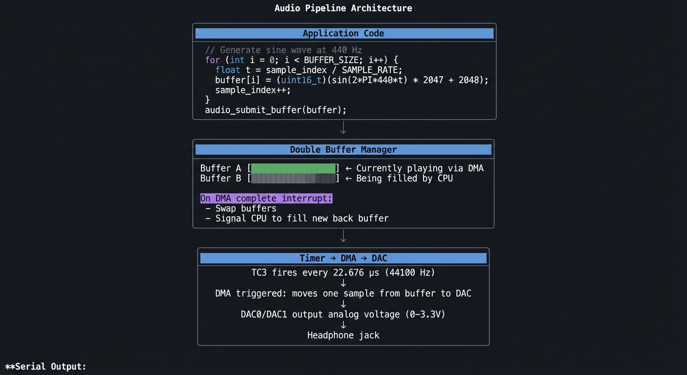 Audio subsystem initialized
DAC0: Enabled, VREF=AVCC (3.3V)
DAC1: Enabled, VREF=AVCC
Sample rate: 44100 Hz
Timer: TC3, period=2720 (120MHz / 44100)
DMA: Channel 0 → DAC0, Channel 1 → DAC1
Buffer size: 256 samples
Latency: 5.8ms (256 / 44100)
Audio subsystem initialized
DAC0: Enabled, VREF=AVCC (3.3V)
DAC1: Enabled, VREF=AVCC
Sample rate: 44100 Hz
Timer: TC3, period=2720 (120MHz / 44100)
DMA: Channel 0 → DAC0, Channel 1 → DAC1
Buffer size: 256 samples
Latency: 5.8ms (256 / 44100)
Playing 440 Hz sine wave… Buffer underrun count: 0 CPU usage: 8% (for sine generation)
Playing sample from flash… Sample: piano_c4.raw, 44100 Hz, 16-bit mono Duration: 2.3 seconds
**Audio output**: Clean 440 Hz tone (A4 note) through headphones.

---

##### Observable Behavior & Validation

- **Sine wave output** is centered at mid‑scale and free of DC offset.
- **Frequency accuracy** stays within 1–2 Hz at 1 kHz.

Example serial output:

```text
[DAC] freq=1000Hz amp=0.6 offset=2048
The Core Question You’re Answering
“How do you output audio samples at precisely 44,100 Hz without using any CPU time during playback?”
The answer is the timer-triggered DMA pattern:
- Timer fires at sample rate (44100 Hz)
- Each timer event triggers a DMA transfer
- DMA moves one sample from buffer to DAC
- DAC converts to analog
- CPU is not involved at all during playback!
Concepts You Must Understand First
Stop and research these before coding:
- DAC Basics
- How does a 12-bit DAC convert numbers to voltage?
- What’s the output range? (0 to VREF)
- What’s the settling time? (How fast can values change?)
- Timer-Triggered DMA
- What’s a DMA trigger source?
- How do you configure TC overflow as DMA trigger?
- What’s the transfer descriptor format?
- Double Buffering
- Why do you need two buffers?
- What happens if you only have one buffer?
- How do you synchronize CPU and DMA access?
- Sample Rate Timing
- 44100 Hz = one sample every 22.676 μs
- At 120 MHz, that’s 2721 clock cycles per sample
- What’s the closest achievable? How much error?
Questions to Guide Your Design
Before implementing, think through these:
- Timer Configuration
- Which timer (TC/TCC) should you use? (Audio library uses some)
- What’s the period value for 44100 Hz?
- What’s the actual sample rate achieved?
- DMA Descriptors
- For circular buffer: what’s the descriptor chain?
- How do you know when to refill the buffer?
- Interrupt on half-complete? On complete?
- Buffer Size Tradeoff
- Larger buffer = more latency, less CPU overhead
- Smaller buffer = less latency, more frequent interrupts
- What’s acceptable for your application?
Thinking Exercise
Design the Timer-DMA-DAC Chain
Before coding, trace one sample’s journey:
Timer TC3 configuration:
  Mode: 16-bit counter
  Clock: GCLK0 (120 MHz)
  Period: 2720 (gives 44117.6 Hz, error = 0.04%)
  Event output: Overflow → DMA trigger

DMA Channel 0 configuration:
  Trigger: TC3 overflow
  Source: buffer[index] (increment after each transfer)
  Destination: DAC0->DATA.reg (fixed)
  Beat size: 16-bit (12-bit DAC, upper bits ignored)
  Block size: 256 samples

Sequence at time T:
  1. TC3 counter reaches 2720 → overflow event
  2. DMA sees trigger, reads buffer[current_index]
  3. DMA writes value to DAC0->DATA.reg
  4. DAC starts conversion (settling time ~1μs)
  5. DMA increments source address
  6. TC3 counter resets to 0
  7. Next sample in ~22.68μs

After 256 samples:
  - DMA block complete interrupt fires
  - ISR: swap buffers, reset DMA source to new buffer
  - CPU: start filling the old buffer with new samples
  - No audio glitch because DMA continues with new buffer
Questions:
- What happens if CPU doesn’t finish filling buffer in time? (Underrun)
- How much time does CPU have to fill 256 samples? (256 / 44100 = 5.8ms)
- What sample rate error is audible? (Generally > 0.1% noticeable)
The Interview Questions They’ll Ask
-
“Explain the timer-triggered DMA pattern for audio. Why is this better than software timing?”
-
“Your audio has occasional ‘pops’. What could cause buffer underruns?”
-
“Calculate the timer period for 48000 Hz sample rate at 120 MHz system clock.”
-
“How do you achieve stereo output with the SAMD51’s dual DACs?”
-
“What’s the tradeoff between buffer size and latency?”
Hints in Layers
Hint 1: Starting Point First get DAC outputting any value (no timer, no DMA). Then add timer. Then add DMA. Then add double buffering.
Hint 2: DAC Configuration
// Enable DAC clock
MCLK->APBDMASK.bit.DAC_ = 1;

// Configure DAC
DAC->CTRLA.bit.ENABLE = 0;  // Disable for config
DAC->CTRLB.reg = DAC_CTRLB_REFSEL_AVCC;  // 3.3V reference
DAC->DACCTRL[0].reg = DAC_DACCTRL_ENABLE | DAC_DACCTRL_CCTRL_CC12M;
DAC->CTRLA.bit.ENABLE = 1;

// Write sample
DAC->DATA[0].reg = sample;  // 0-4095
Hint 3: Timer for DMA Trigger
// TC3 as DMA trigger
TC3->COUNT16.CTRLA.reg = TC_CTRLA_MODE_COUNT16 | TC_CTRLA_PRESCALER_DIV1;
TC3->COUNT16.WAVE.reg = TC_WAVE_WAVEGEN_MFRQ;  // Match frequency mode
TC3->COUNT16.CC[0].reg = 2720;  // 44100 Hz at 120 MHz
TC3->COUNT16.EVCTRL.reg = TC_EVCTRL_OVFEO;  // Overflow event output
TC3->COUNT16.CTRLA.bit.ENABLE = 1;
Hint 4: DMA Trigger Connection
// Configure DMA to trigger on TC3 overflow
DMAC->Channel[0].CHCTRLA.reg = DMAC_CHCTRLA_TRIGSRC(TC3_DMAC_ID_OVF) |
                                DMAC_CHCTRLA_TRIGACT_BURST;
Books That Will Help
| Topic | Book | Chapter |
|---|---|---|
| DAC fundamentals | “The Art of Electronics” by Horowitz & Hill | Ch. 13 |
| Audio programming | “The Audio Programming Book” | Ch. 1-2 |
| Real-time audio | “Real-Time DSP” by Kuo & Gan | Ch. 2 |
| SAMD51 DAC | SAMD51 Datasheet | DAC chapter |
Common Pitfalls & Debugging
| Problem | Cause | Fix | Verification |
|---|---|---|---|
| No output | DAC not enabled | Check CTRLA.ENABLE | Write test value, measure voltage |
| Wrong frequency | Timer period wrong | Recalculate period | Measure with scope/frequency counter |
| Distorted audio | Buffer underrun | Increase buffer size | Monitor underrun counter |
| DC offset | Wrong sample format | Center samples at mid-scale (2048) | Check DC voltage |
| DMA doesn’t trigger | Event routing wrong | Check EVSYS config | Poll DMA status |
Advanced Pitfalls
- Aliasing when you generate frequencies near Nyquist.
- DC offset if you forget mid‑scale bias.
Learning Milestones
- DAC outputs voltage → Basic DAC working
- Timer fires at 44100 Hz → Timing established
- DMA transfers samples → Automated playback
- Double buffer works → Glitch-free continuous audio
- Sine wave sounds clean → Full audio pipeline operational
Project 15: Bare-Metal I2C Driver for ADXL343 (Pure C)
- File: LEARN_NEOTRELLIS_M4_DEEP_DIVE.md
- Main Programming Language: C (bare-metal)
- Alternative Programming Languages: None
- Coolness Level: Level 3: Genuinely Clever
- Business Potential: 1. The “Resume Gold”
- Difficulty: Level 4: Expert
- Knowledge Area: I2C Protocol, SERCOM I2C Mode, Sensor Drivers
- Software or Tool: arm-none-eabi-gcc, Logic analyzer helpful
- Main Book: “Making Embedded Systems” by Elecia White
What you’ll build: A complete I2C master driver and ADXL343 accelerometer driver from scratch. Read X/Y/Z acceleration values, configure data rate and range, and implement tap detection—all without any library code.
Why it teaches I2C communication: I2C is ubiquitous in embedded systems—sensors, EEPROMs, displays all use it. Understanding the protocol at the register level (start conditions, addressing, ACK/NACK) makes you capable of working with any I2C device.
Core challenges you’ll face:
- I2C protocol implementation → Start/stop conditions, addressing
- SERCOM as I2C master → Different from SPI/UART configuration
- Multi-byte reads → Reading 6 bytes (X/Y/Z, each 16-bit)
- Register access patterns → Write register address, then read data
- Sensor configuration → Power modes, data rates, ranges
Key Concepts:
- I2C protocol: “Making Embedded Systems” Ch. 7
- SERCOM I2C mode: SAMD51 Datasheet - SERCOM chapter
- ADXL343 registers: ADXL343 Datasheet
- Two’s complement: Signed integer representation
Difficulty: Expert Time estimate: 2-3 weeks (20-30 hours) Prerequisites: Projects 11-13 completed
Real World Outcome
Direct accelerometer access from bare-metal code:
                    I2C Driver Architecture

    ┌─────────────────────────────────────────────────────────────────┐
    │                      Application Code                           │
    │                                                                 │
    │   // Initialize accelerometer                                   │
    │   adxl343_init();                                              │
    │   adxl343_set_range(ADXL343_RANGE_2G);                         │
    │                                                                 │
    │   // Read acceleration                                          │
    │   int16_t x, y, z;                                             │
    │   adxl343_read_xyz(&x, &y, &z);                                │
    │   printf("X: %d  Y: %d  Z: %d\n", x, y, z);                    │
    └─────────────────────────┬───────────────────────────────────────┘
                              │
                              ▼
    ┌─────────────────────────────────────────────────────────────────┐
    │                    ADXL343 Driver Layer                         │
    │                                                                 │
    │   uint8_t adxl343_read_reg(uint8_t reg) {                      │
    │     i2c_start();                                               │
    │     i2c_write(ADXL343_ADDR << 1);     // Write mode            │
    │     i2c_write(reg);                    // Register address     │
    │     i2c_repeated_start();                                      │
    │     i2c_write((ADXL343_ADDR << 1) | 1); // Read mode           │
    │     uint8_t data = i2c_read_nack();    // Read with NACK      │
    │     i2c_stop();                                                │
    │     return data;                                                │
    │   }                                                             │
    └─────────────────────────┬───────────────────────────────────────┘
                              │
                              ▼
    ┌─────────────────────────────────────────────────────────────────┐
    │                     I2C Driver Layer                            │
    │                                                                 │
    │   i2c_start():    SDA ↓ while SCL high                         │
    │   i2c_stop():     SDA ↑ while SCL high                         │
    │   i2c_write(b):   Shift out 8 bits, read ACK                   │
    │   i2c_read_ack(): Shift in 8 bits, send ACK                    │
    │   i2c_read_nack(): Shift in 8 bits, send NACK                  │
    └─────────────────────────┬───────────────────────────────────────┘
                              │
                              ▼
    ┌─────────────────────────────────────────────────────────────────┐
    │                     SERCOM Hardware                             │
    │                                                                 │
    │   SDA: PA08 (SERCOM2 PAD0)                                     │
    │   SCL: PA09 (SERCOM2 PAD1)                                     │
    │   Clock: 400 kHz (Fast mode)                                   │
    └─────────────────────────────────────────────────────────────────┘

**Serial Output:**
I2C Driver initialized SERCOM: 2 SDA: PA08, SCL: PA09 Clock: 400 kHz (Fast mode)
Scanning I2C bus… Device found at 0x1D (ADXL343 accelerometer) Device found at 0x53 (alt address)
ADXL343 initialized Device ID: 0xE5 (correct!) Data rate: 100 Hz Range: ±2g
Continuous readings: X: 5 Y: -12 Z: 256 (flat on desk) X: 128 Y: 3 Z: 223 (tilted right) X: -5 Y: 250 Z: 42 (tilted forward) TAP detected! (X-axis)
---

##### Observable Behavior & Validation

- **Device ID read** succeeds consistently with zero NACKs.
- **Acceleration stream** shows stable values at rest (~1g on Z).

Example serial output:

```text
[I2C] addr=0x1D ok
[ACCEL] x=+0.01g y=-0.02g z=+0.98g
The Core Question You’re Answering
“How does the I2C protocol allow multiple devices to share two wires, and how do you implement it at the register level?”
I2C uses two open-drain lines (SDA, SCL) with pull-up resistors. Every transaction starts with a START condition (SDA falls while SCL high), followed by a 7-bit address to select which device responds. Only the addressed device ACKs, all others ignore.
Concepts You Must Understand First
Stop and research these before coding:
- I2C Electrical
- What’s “open-drain”? Why does it matter?
- What do pull-up resistors do?
- What happens if two devices drive the bus?
- I2C Protocol
- What defines START and STOP conditions?
- How does addressing work? (7-bit address + R/W bit)
- What’s ACK vs NACK? When does each occur?
- Register Access Pattern
- Write: START, addr+W, reg, data, STOP
- Read: START, addr+W, reg, rSTART, addr+R, [read data], STOP
- Why is repeated start needed for reads?
- ADXL343 Specifics
- What registers contain X/Y/Z data?
- How is data formatted? (16-bit, two’s complement)
- How do you convert raw values to g?
Questions to Guide Your Design
Before implementing, think through these:
- Abstraction Layers
- Low level: i2c_start(), i2c_write(), i2c_read()
- Mid level: i2c_write_reg(), i2c_read_reg()
- High level: adxl343_read_xyz()
- How much abstraction is appropriate?
- Error Handling
- What if no device ACKs? (Bus error)
- What if device NACKs mid-transfer?
- How do you recover from a hung bus?
- Multi-Byte Reads
- ADXL343 X/Y/Z are 6 bytes (DATAX0/X1, Y0/Y1, Z0/Z1)
- How do you read all 6 efficiently? (Auto-increment)
- Why read all 6 in one transaction? (Data consistency)
Thinking Exercise
Trace an I2C Read Transaction
Before coding, trace reading register 0x00 (DEVID) from ADXL343:
ADXL343 address: 0x1D (7-bit)

Transaction to read DEVID:

1. START condition
   SDA: ─────╲_____
   SCL: ─────────__

2. Send address byte (0x1D << 1 | 0 = 0x3A)
   SDA: [0][0][1][1][1][0][1][0]  ← 0x3A
   SCL: _╱╲_╱╲_╱╲_╱╲_╱╲_╱╲_╱╲_╱╲_
   After 8 bits, release SDA for ACK
   SDA: ___________╲ (device pulls low = ACK)
   SCL: ___________╱╲

3. Send register address (0x00)
   SDA: [0][0][0][0][0][0][0][0]
   SCL: _╱╲_╱╲_╱╲_╱╲_╱╲_╱╲_╱╲_╱╲_
   SDA: ___________╲ (ACK)

4. Repeated START
   SDA: ────╱───╲__
   SCL: ────────╱──

5. Send address byte for read (0x3B)
   SDA: [0][0][1][1][1][0][1][1]  ← 0x3B (bit 0 = 1 = read)
   SCL: ...
   SDA: ___________╲ (ACK)

6. Read data byte
   Master releases SDA
   ADXL343 drives: [1][1][1][0][0][1][0][1] ← 0xE5 (DEVID)
   Master reads each bit on SCL rising edge
   Master sends NACK (SDA high during 9th clock) to signal end

7. STOP condition
   SDA: _____╱─────
   SCL: ───╱───────
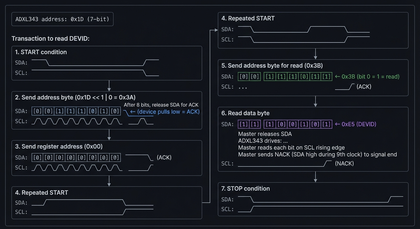
Questions:
- Why does the master release SDA after address byte?
- Why NACK on the last read byte?
- What happens if you send ACK on the last byte? (Device tries to send more)
The Interview Questions They’ll Ask
-
“Walk me through an I2C read transaction at the bit level.”
-
“The ADXL343 isn’t responding. How would you debug this?”
-
“Why does I2C need pull-up resistors? What value would you use?”
-
“How do you convert raw ADXL343 data to g? Show the math.”
-
“What’s clock stretching in I2C and how do you handle it?”
Hints in Layers
Hint 1: Starting Point First implement I2C bus scan (try all addresses, see who ACKs). This verifies basic I2C before worrying about specific registers.
Hint 2: SERCOM I2C Configuration
// SERCOM2 as I2C master
SERCOM2->I2CM.CTRLA.reg = SERCOM_I2CM_CTRLA_MODE_I2C_MASTER |
                          SERCOM_I2CM_CTRLA_SPEED(0);  // Standard mode
SERCOM2->I2CM.BAUD.reg = ((F_CPU / (2 * 400000)) - 1);  // 400kHz
SERCOM2->I2CM.CTRLA.bit.ENABLE = 1;
// Force bus state to IDLE
SERCOM2->I2CM.STATUS.bit.BUSSTATE = 1;
Hint 3: Write Byte with ACK Check
bool i2c_write(uint8_t data) {
  SERCOM2->I2CM.DATA.reg = data;
  while (!SERCOM2->I2CM.INTFLAG.bit.MB);  // Wait for master on bus
  return !SERCOM2->I2CM.STATUS.bit.RXNACK;  // Return true if ACK received
}
Hint 4: ADXL343 Data Conversion
// Raw values are 10-bit, signed, left-justified
// In ±2g mode: 1 LSB = 3.9 mg
int16_t raw = (DATAX1 << 8) | DATAX0;
float g = raw * 0.0039;  // Convert to g
Books That Will Help
| Topic | Book | Chapter |
|---|---|---|
| I2C protocol | “Making Embedded Systems” by White | Ch. 7 |
| SERCOM I2C | SAMD51 Datasheet | SERCOM chapter |
| ADXL343 | ADXL343 Datasheet | All |
| Sensor interfacing | “Sensors and Signal Conditioning” | Ch. 4 |
Common Pitfalls & Debugging
| Problem | Cause | Fix | Verification |
|---|---|---|---|
| No ACK | Wrong address | Check address (0x1D, not 0x3A) | Bus scan all addresses |
| Bus stuck | No pull-ups | Add 4.7kΩ pull-ups to VCC | Check SDA/SCL with scope |
| Wrong data | Byte order | ADXL343 is little-endian | Read DEVID (should be 0xE5) |
| Data = 0 | Device not active | Write to POWER_CTL register | Check device status registers |
| Bus errors | Clock stretching | Implement timeout | Monitor bus state |
Advanced Pitfalls
- Clock stretching not handled (some I2C devices stretch).
- Bus lockup after a missed STOP; recover with manual toggles.
Learning Milestones
- I2C scan finds device → Basic I2C working
- DEVID reads 0xE5 → Register reads working
- X/Y/Z values make sense → Multi-byte reads working
- Values change with tilt → Full sensor operational
- Tap detection works → Advanced features implemented
TIER 4: ADVANCED INTEGRATION PROJECTS
These final projects combine everything you’ve learned—blending CircuitPython concepts, Arduino audio expertise, and bare-metal C knowledge into complex, impressive systems that demonstrate complete mastery.
Project 16: Complete MIDI DAW Controller (Full Integration)
- File: LEARN_NEOTRELLIS_M4_DEEP_DIVE.md
- Main Programming Language: Arduino C++ (with bare-metal optimizations)
- Alternative Programming Languages: Bare-metal C, CircuitPython
- Coolness Level: Level 5: Pure Magic (Super Cool)
- Business Potential: 4. The “Open Core” Infrastructure
- Difficulty: Level 4: Expert
- Knowledge Area: USB MIDI, Real-Time Systems, Human Interface Design
- Software or Tool: Arduino IDE, Ableton Live/Logic Pro X
- Main Book: “Making Embedded Systems” by Elecia White
What you’ll build: A professional-grade MIDI controller that rivals commercial products like Novation Launchpad or Ableton Push. Features include: multiple operational modes (clip launch, mixer, drum machine, step sequencer), RGB feedback from the DAW, velocity-sensitive input, accelerometer-based expression control, and seamless mode switching. This is a controller you’d actually use for music production.
Why it teaches integration mastery: This project requires synthesizing every skill: USB protocols, real-time audio concepts, LED driving, sensor input, and clean architecture. You must balance responsiveness, visual feedback, and musical timing—the complete embedded systems challenge.
Core challenges you’ll face:
- Mode management → Clean state machine for multiple operational modes
- DAW bidirectional communication → Sending MIDI to DAW AND receiving LED feedback
- Velocity handling → Converting button press timing to velocity (or using pressure)
- Performance timing → Sub-millisecond latency for live performance
- User experience design → Making complex features discoverable and intuitive
Key Concepts:
- USB MIDI bidirectional: MIDI to/from DAW for visual feedback
- State machines: “Clean Code” Ch. 9 - managing complexity
- Real-time constraints: “Making Embedded Systems” Ch. 10
- HID design: Creating intuitive interfaces
Difficulty: Expert Time estimate: 4-6 weeks (50-80 hours) Prerequisites: Projects 4 (MIDI), 6 (Audio), and 11-15 (bare-metal understanding)
Real World Outcome
You have a controller that integrates seamlessly with professional DAWs:
                    DAW Controller Architecture

    ┌──────────────────────────────────────────────────────────────┐
    │                         DAW (Ableton/Logic)                   │
    │                                                               │
    │   ┌─────────────┐   ┌─────────────┐   ┌─────────────────┐   │
    │   │   Session   │   │    Mixer    │   │    Drum Rack   │   │
    │   │   View      │   │    View     │   │      View      │   │
    │   └──────┬──────┘   └──────┬──────┘   └───────┬────────┘   │
    │          │                 │                   │            │
    │          │         MIDI Feedback (LED colors)  │            │
    │          └─────────────────┼───────────────────┘            │
    │                            │                                 │
    └────────────────────────────┼─────────────────────────────────┘
                                 │ USB MIDI
                                 ▼
    ┌────────────────────────────────────────────────────────────────┐
    │                        NeoTrellis M4                           │
    │                                                                │
    │   Mode: [SESSION]  [MIXER]  [DRUMS]  [SEQUENCER]              │
    │                                                                │
    │   ┌────┬────┬────┬────┬────┬────┬────┬────┐                   │
    │   │Clp1│Clp2│Clp3│Clp4│Clp5│Clp6│Clp7│Clp8│  ← Track 1       │
    │   ├────┼────┼────┼────┼────┼────┼────┼────┤    clips          │
    │   │ G  │ G  │ Y  │    │ R  │    │    │    │  ← Color from DAW │
    │   ├────┼────┼────┼────┼────┼────┼────┼────┤    (G=playing,    │
    │   │Clp1│Clp2│Clp3│Clp4│Clp5│Clp6│Clp7│Clp8│    Y=triggered,  │
    │   ├────┼────┼────┼────┼────┼────┼────┼────┤    R=recording)   │
    │   │MODE│STOP│REC │PLAY│◄◄  │ ►► │SHFT│    │  ← Controls       │
    │   └────┴────┴────┴────┴────┴────┴────┴────┘                   │
    │                                                                │
    │   Accelerometer: X → Pan control                               │
    │                  Y → Filter sweep                              │
    │                  Z → Expression (pressure substitute)          │
    └────────────────────────────────────────────────────────────────┘


                    Mode Switching State Machine

                         ┌──────────────┐
                         │    BOOT      │
                         │ (load prefs) │
                         └──────┬───────┘
                                │
                                ▼
                    ┌───────────────────────┐
            ┌───────│      SESSION          │───────┐
            │       │  (clip launching)     │       │
            │       └───────────┬───────────┘       │
            │                   │                   │
            │ MODE+1           MODE+2           MODE+3
            ▼                   ▼                   ▼
    ┌──────────────┐   ┌──────────────┐   ┌──────────────┐
    │    MIXER     │   │    DRUMS     │   │  SEQUENCER   │
    │ (faders/pan) │   │ (drum pads)  │   │ (step edit)  │
    └──────────────┘   └──────────────┘   └──────────────┘
            │                   │                   │
            └───────────────────┴───────────────────┘
                     Any MODE button returns


**Serial Debug Output:**
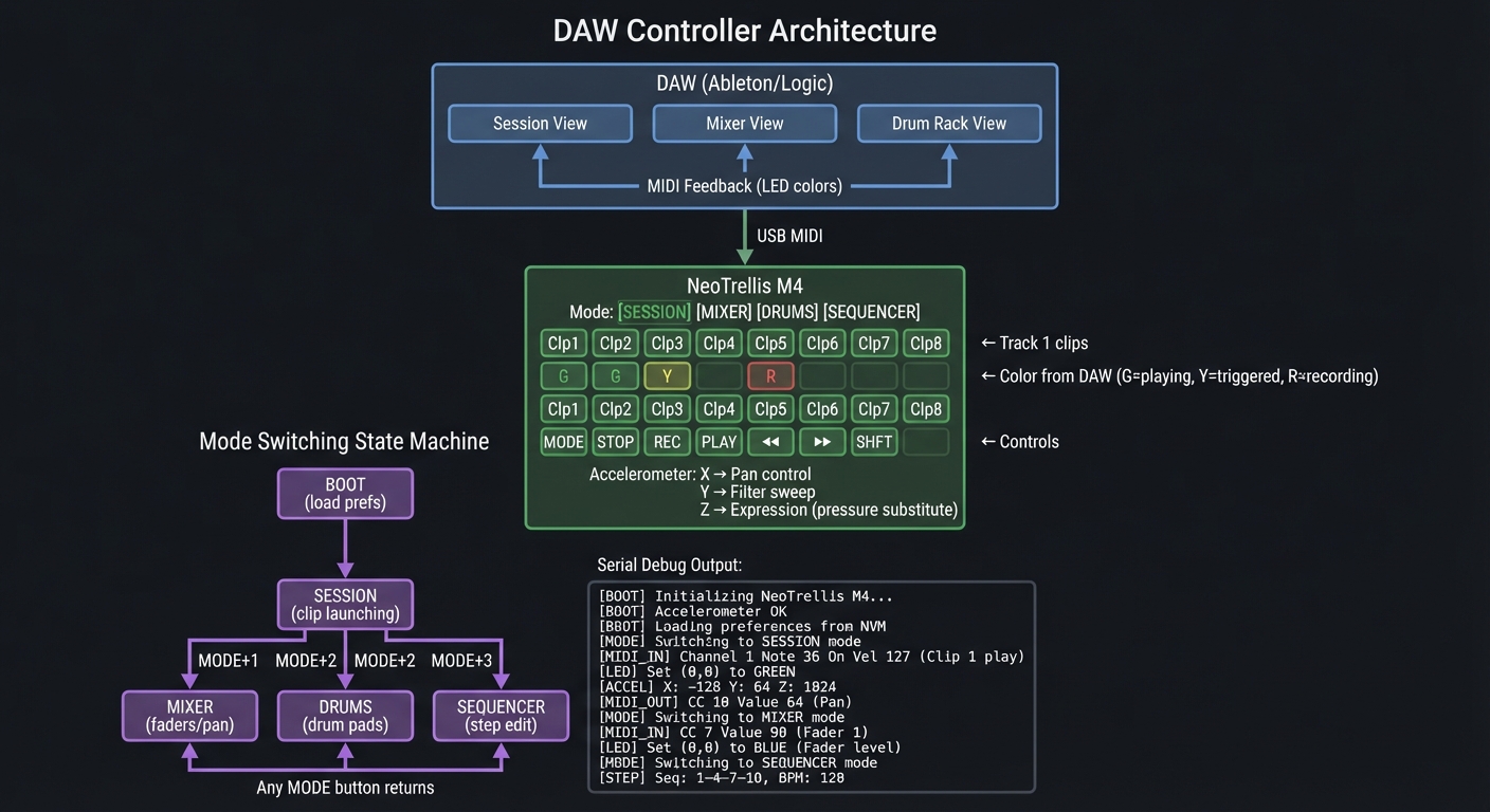 NeoTrellis DAW Controller v2.0
Initializing…
NeoPixels: OK (32 LEDs, DMA)
Accelerometer: OK (ADXL343 @ 0x1D)
USB MIDI: OK (Device: “NeoTrellis Controller”)
NeoTrellis DAW Controller v2.0
Initializing…
NeoPixels: OK (32 LEDs, DMA)
Accelerometer: OK (ADXL343 @ 0x1D)
USB MIDI: OK (Device: “NeoTrellis Controller”)
Waiting for DAW connection… DAW connected! (Ableton Live 11) Receiving LED feedback on channel 16
[SESSION MODE] Button 0,0 pressed (velocity 112) → Note C3 sent DAW feedback: LED 0,0 → GREEN (clip playing) DAW feedback: LED 2,0 → YELLOW (clip triggered, waiting for 1)
Mode button pressed → MIXER MODE Accelerometer X mapped to Track 1 Pan: -23 Accelerometer Y mapped to Track 1 Filter: 6.2kHz
Mode button pressed → DRUMS MODE Velocity sensing active (time-based) Button 3,2 pressed → D2 (velocity 89) → Snare
Mode button pressed → SEQUENCER MODE Step 1: C3 on Step 2: – off Step 3: E3 on … Pattern length: 16 steps BPM: 120 (synced from DAW)
---

##### Observable Behavior & Validation

- **Clip launch buttons** match DAW grid with no off‑by‑one errors.
- **Transport controls** (play/stop/rec) update DAW state instantly.

Example serial output:

```text
[MIDI] CC#20 value=127 (Play)
The Core Question You’re Answering
“How do you build a complex interactive system with multiple operational modes while maintaining real-time responsiveness and clean architecture?”
This is the quintessential embedded systems design challenge. You must balance competing requirements: visual responsiveness, input latency, clean code architecture, and user experience—all on a microcontroller with limited resources.
Concepts You Must Understand First
Stop and research these before coding:
- State Machine Architecture
- How do you represent multiple modes cleanly?
- What’s a state transition table?
- How do you handle mode-specific behavior without massive switch statements?
- Book Reference: “Clean Code” Ch. 9 - State machines
- MIDI Bidirectional Communication
- How does MIDI feedback from DAW work?
- What’s SysEx and how is it used for LED control?
- How do you handle MIDI running status?
- Book Reference: MIDI 1.0 Specification - System Exclusive
- Velocity Sensing Without Pressure Sensors
- How do commercial controllers detect velocity?
- What’s the relationship between press time and velocity?
- How do you calibrate for different playing styles?
- Real-Time System Design
- What’s the acceptable latency for live performance? (~10ms max)
- How do you prioritize tasks?
- What can cause latency spikes?
- Book Reference: “Making Embedded Systems” Ch. 10
Questions to Guide Your Design
Before implementing, think through these:
- Mode Management
- How many operational modes do you need?
- What state persists across mode switches?
- How do you indicate current mode visually?
- DAW Communication
- How do you receive LED color commands from the DAW?
- What MIDI channel/notes for feedback vs. output?
- How do you handle different DAW protocols (Ableton vs. Logic)?
- Performance
- What’s your target latency?
- Which operations can be batched?
- How do you handle 32 LEDs updating at 60fps?
- User Experience
- How does the user switch modes?
- How do you handle modifier keys (Shift)?
- What visual feedback confirms actions?
Thinking Exercise
Design the State Machine
Before coding, diagram the state machine for mode switching:
States: BOOT, SESSION, MIXER, DRUMS, SEQUENCER, SHIFT_HELD

Transitions:
  BOOT → SESSION (after initialization)
  SESSION → MIXER (MODE + button 0)
  SESSION → DRUMS (MODE + button 1)
  SESSION → SEQUENCER (MODE + button 2)
  Any → SHIFT_HELD (SHIFT pressed)
  SHIFT_HELD → previous (SHIFT released)

For each state, define:
  - Entry action (what happens on transition IN)
  - Exit action (what happens on transition OUT)
  - Button map (what each button does in this mode)
  - LED pattern (how to display this mode)
Questions:
- How do you store the “previous state” for returning from SHIFT?
- What happens if MODE is pressed during SHIFT?
- How do you animate the mode transition?
The Interview Questions They’ll Ask
-
“Walk me through your state machine architecture. How do you avoid massive switch statements?”
-
“What’s your latency budget from button press to MIDI output? How did you measure it?”
-
“How do you handle DAW-specific MIDI protocols without recompiling?”
-
“The LEDs flicker when the DAW sends rapid updates. How would you fix this?”
-
“How would you add velocity sensitivity to buttons that don’t have pressure sensors?”
Hints in Layers
Hint 1: Starting Point Start with just two modes (SESSION and DRUMS). Get mode switching and basic MIDI working before adding complexity. Use a simple array of function pointers for mode-specific behavior.
Hint 2: State Machine Structure
typedef void (*ModeHandler)(uint8_t x, uint8_t y, bool pressed);
typedef void (*ModeEnter)();
typedef void (*ModeExit)();
struct Mode {
ModeEnter enter;
ModeExit exit;
ModeHandler buttonHandler;
ModeHandler ledUpdate;
};
Mode modes[] = {
{sessionEnter, sessionExit, sessionButton, sessionLED},
{mixerEnter, mixerExit, mixerButton, mixerLED},
// ...
};
uint8_t currentMode = 0;
Hint 3: Velocity from Timing
// Track when button was first detected
uint32_t buttonDownTime[32];
// On button scan:
if (justPressed) {
buttonDownTime[i] = millis();
}
if (justReleased) {
uint32_t pressTime = millis() - buttonDownTime[i];
// Faster press = higher velocity
// Typical: 5ms = velocity 127, 100ms = velocity 1
uint8_t velocity = constrain(map(pressTime, 5, 100, 127, 1), 1, 127);
sendMIDI(NOTE_ON, notes[currentMode][i], velocity);
}
Hint 4: DAW Feedback Handling
// MIDI callback for incoming messages
void handleNoteOn(byte channel, byte note, byte velocity) {
if (channel == 16) { // Feedback channel
// Note = button index, velocity = color
uint8_t x = note % 8;
uint8_t y = note / 8;
uint32_t color = velocityToColor(velocity);
setLED(x, y, color);
}
}
uint32_t velocityToColor(byte v) {
// Map Ableton's color palette
switch(v) {
case 1: return 0x00FF00; // Green = playing
case 2: return 0xFFFF00; // Yellow = triggered
case 3: return 0xFF0000; // Red = recording
// ...
}
}
Books That Will Help
| Topic | Book | Chapter |
|---|---|---|
| State machines | “Clean Code” by Martin | Ch. 9 |
| Real-time design | “Making Embedded Systems” by White | Ch. 10 |
| MIDI protocol | MIDI 1.0 Specification | SysEx, Running Status |
| USB MIDI | USB MIDI Specification | All |
| HID design | “Don’t Make Me Think” by Krug | Ch. 1-3 |
Common Pitfalls & Debugging
| Problem | Cause | Fix | Verification |
|---|---|---|---|
| Mode switch lag | Too much work in transition | Defer LED updates to main loop | Profile with millis() |
| LED flicker | DAW sending many updates | Implement change detection | Log incoming MIDI |
| Button double-triggers | Debounce issue | Add 20ms debounce | Serial log press times |
| MIDI choke | Too many messages | Implement running status | Monitor MIDI stream |
| Accelerometer jitter | No filtering | Add low-pass filter | Plot raw vs filtered |
Advanced Pitfalls
- Duplicate CC mapping causes conflicting DAW control.
- LED feedback lag if you don’t parse DAW return messages.
Learning Milestones
- Two modes work → Basic state machine
- DAW receives notes → USB MIDI output working
- LEDs update from DAW → Bidirectional MIDI working
- Velocity works → Timing-based velocity
- All modes polished → Complete product
Project 17: Real-Time Audio Visualizer with External Display (Hardware Extension)
- File: LEARN_NEOTRELLIS_M4_DEEP_DIVE.md
- Main Programming Language: Bare-metal C (with assembly optimization)
- Alternative Programming Languages: Arduino C++
- Coolness Level: Level 5: Pure Magic (Super Cool)
- Business Potential: 2. The “Micro-SaaS / Pro Tool”
- Difficulty: Level 5: Master
- Knowledge Area: Digital Signal Processing, SPI Displays, DMA, FFT
- Software or Tool: arm-none-eabi-gcc, External SPI LCD (e.g., ILI9341)
- Main Book: “The Scientist and Engineer’s Guide to Digital Signal Processing” by Steven Smith
What you’ll build: A real-time audio spectrum analyzer that takes line-in audio (via ADC), performs FFT analysis, and displays a high-resolution visualization on an external SPI LCD. The NeoTrellis buttons control visualization modes (spectrum bars, oscilloscope, waterfall), and NeoPixels provide ambient lighting that pulses with the beat. This is the ultimate integration: audio input, DSP, and multiple outputs all in bare-metal C.
Why it teaches complete system integration: This project combines every hardware subsystem: ADC for audio input, FFT for processing, SPI for display, DMA for transfers, timers for synchronization, and GPIO for buttons. It’s the capstone of bare-metal programming.
Core challenges you’ll face:
- ADC audio capture → Sampling audio at 44.1kHz with DMA
- FFT implementation → Computing 512-point FFT in real-time
- SPI display driving → Pushing pixels fast enough for smooth animation
- Beat detection → Extracting rhythm from spectrum data
- All running simultaneously → Balancing multiple real-time tasks
Key Concepts:
- ADC with DMA: Audio capture without CPU intervention
- FFT algorithm: “DSP Guide” Ch. 12 - The FFT
- SPI displays: ILI9341 command protocol
- Real-time scheduling: Managing multiple time-critical tasks
Difficulty: Master Time estimate: 6-8 weeks (80-100 hours) Prerequisites: All previous projects, especially 11-15 (bare-metal), 8 (FFT concepts)
Real World Outcome
A stunning audio visualizer with external display:
System Architecture
┌─────────────────────────────────────────────────────────────────┐
│ Audio Input Stage │
│ │
│ Line In ─────┬───────[Bias Circuit]───────┬───→ ADC (PA02) │
│ │ │ │
│ Audio Jack DC Blocking │
│ 3.5mm + Bias to 1.65V │
│ │
│ ADC: 12-bit @ 44.1kHz, DMA to buffer │
└────────────────────────────┬────────────────────────────────────┘
│
▼
┌─────────────────────────────────────────────────────────────────┐
│ DSP Processing │
│ │
│ ┌──────────┐ ┌──────────┐ ┌──────────┐ ┌──────────┐ │
│ │ Window │ → │ 512-pt │ → │ Magnitude│ → │ Peak │ │
│ │ (Hanning)│ │ FFT │ │ Calc │ │ Detect │ │
│ └──────────┘ └──────────┘ └──────────┘ └──────────┘ │
│ │
│ Processing: 512 samples = 11.6ms window │
│ FFT bins: 256 usable (up to 22kHz) │
│ Update rate: ~60 FPS │
└────────────────────────────┬────────────────────────────────────┘
│
┌────────────┴────────────┐
│ │
▼ ▼
┌──────────────────────────┐ ┌──────────────────────────────┐
│ ILI9341 Display │ │ NeoTrellis LEDs │
│ (320x240) │ │ (4x8 = 32) │
│ │ │ │
│ ┌───────────────────┐ │ │ ┌───┬───┬───┬───┬───┐ │
│ │▓▓▓▓ │ │ │ │ █ │ │ █ │ │ █ │ │
│ │▓▓▓▓▓▓ │ │ │ │ █ │ │ █ │ █ │ █ │ │
│ │▓▓▓▓▓▓▓▓ │ │ │ │ █ │ █ │ █ │ █ │ █ │ │
│ │▓▓▓▓▓▓▓▓▓▓ │ │ │ │ █ │ █ │ █ │ █ │ █ │ │
│ │▓▓▓▓▓▓▓▓▓▓▓▓▓▓ │ │ │ └───┴───┴───┴───┴───┘ │
│ │▓▓▓▓▓▓▓▓▓▓▓▓▓▓▓▓▓▓│ │ │ Bars pulse with bass │
│ └───────────────────┘ │ │ │
│ 31.25Hz ──────── 16kHz │ │ Mode buttons on bottom row │
│ │ │ │
│ SPI @ 40MHz + DMA │ │ [SPEC][WAVE][WTFL][BEAT] │
└──────────────────────────┘ └──────────────────────────────┘
Visualization Modes
┌────────────────────────────────────────────────────────────────┐
│ SPECTRUM: Classic bar graph, 32 bands, logarithmic scale │
│ │
│ ▓▓▓▓ │
│ ▓▓▓▓▓▓▓▓ │
│ ▓▓▓▓▓▓▓▓▓▓▓▓▓▓ │
│ ▓▓▓▓▓▓▓▓▓▓▓▓▓▓▓▓▓▓▓▓▓▓ │
│ 32Hz 125Hz 500Hz 2kHz 8kHz │
└────────────────────────────────────────────────────────────────┘
┌────────────────────────────────────────────────────────────────┐
│ OSCILLOSCOPE: Waveform display, trigger on zero-crossing │
│ │
│ ╭─╮ ╭─╮ ╭─╮ │
│ ╱ ╲ ╱ ╲ ╱ ╲ │
│ ───╱─────╲──╱─────╲──╱─────╲── │
│ ╲ ╱ ╲ ╱ │
│ ╰─╯ ╰─╯ │
└────────────────────────────────────────────────────────────────┘
┌────────────────────────────────────────────────────────────────┐
│ WATERFALL: Scrolling spectrogram, time flows down │
│ │
│ ████░░░░████░░░░░░████░░░░ ← Now │
│ ░░████░░░░████░░░░░░████░░ │
│ ░░░░████░░░░████░░░░░░████ │
│ ████░░░░████░░░░░░████░░░░ │
│ Color: blue(low) → green → yellow → red(high) │
└────────────────────────────────────────────────────────────────┘
**Serial Debug Output:**
Audio Visualizer v1.0 (Bare-metal) Initializing… Clock: 120 MHz ADC: 12-bit, 44100 Hz, DMA channel 0 FFT: 512-point, Hanning window Display: ILI9341 320x240, SPI @ 40MHz, DMA channel 1 NeoPixels: 32 LEDs, DMA channel 2
Audio input: Line-in on PA02 DC bias: 1.647V (good) Signal detected: -12 dBFS peak
Performance: ADC fill time: 11.61 ms (512 samples) FFT compute: 0.89 ms (ARM CMSIS DSP) Display render: 4.2 ms NeoPixel update: 1.0 ms Total frame: 17.7 ms (56 FPS)
Beat detection: Bass energy: 2341 (threshold: 2000) BEAT! (interval: 500ms = 120 BPM)
Mode: SPECTRUM Peak: 125 Hz (bass), 2.5 kHz (vocals)
---
##### Observable Behavior & Validation
- **Display + LEDs** stay in sync; no tearing at ~60 FPS.
- **Audio input** drives visuals with minimal latency.
Example serial output:
```text
[VIS] fps=58 frame_ms=17.2 audio_lag_ms=6
The Core Question You’re Answering
“How do you build a system that handles continuous real-time audio processing while simultaneously driving multiple output devices, all in bare-metal C?”
This is the ultimate embedded systems integration challenge. You must orchestrate: ADC sampling at precise intervals, FFT processing within the audio window, display updates at visual frame rate, and LED animations—all with minimal CPU involvement using DMA.
Concepts You Must Understand First
Stop and research these before coding:
- ADC with DMA
- How does ADC continuous conversion mode work?
- How do you trigger DMA from ADC completion?
- What’s double-buffering and why is it essential?
- Book Reference: SAMD51 Datasheet - ADC + DMAC chapters
- FFT Fundamentals
- What does FFT output represent?
- Why do you need a window function?
- How do you convert FFT bins to frequencies?
- Book Reference: “DSP Guide” Ch. 12 - The FFT
- SPI Display Protocol
- How does ILI9341 command/data work?
- What’s the pixel format (RGB565)?
- How do you set a drawing window?
- Book Reference: ILI9341 Datasheet
- DMA Chaining
- How do you run multiple DMA channels simultaneously?
- What’s DMA priority and how does it affect performance?
- How do you synchronize DMA completion with processing?
Questions to Guide Your Design
Before implementing, think through these:
- Timing Budget
- 44100 Hz sampling = 22.68 µs per sample
- 512 samples = 11.6 ms of audio
- Display at 60 FPS = 16.7 ms per frame
- How do you fit FFT + display in this budget?
- Buffer Strategy
- How many audio buffers do you need? (Double buffering minimum)
- When does FFT run? (While next buffer fills)
- How do you prevent audio glitches during display updates?
- Display Optimization
- Drawing 32 bars × 200 pixels = 6400 pixels minimum
- At 16 bits/pixel, SPI @ 40MHz = 2.56 ms minimum
- How do you optimize? (Only redraw changed areas)
- Memory Layout
- FFT needs 512 complex floats = 4KB
- Display buffer = 320×240×2 = 150KB (won’t fit!)
- Solution: Line-by-line rendering
Thinking Exercise
Design the DMA Architecture
Before coding, diagram the DMA channels and their interactions:
DMA Channel 0: ADC → Audio Buffer A/B
Trigger: ADC RESRDY
Transfer: 16-bit, 512 samples
Ping-pong: Buffer A fills while processing B
DMA Channel 1: Display Buffer → SPI
Trigger: SPI DRE (data register empty)
Transfer: 16-bit pixels
Action: Set up next line transfer on completion
DMA Channel 2: LED Buffer → SERCOM (SPI mode for NeoPixels)
Trigger: Manual start
Transfer: 8-bit, 96 bytes (32 LEDs × 3 colors)
Timing: Run after audio processing, before next ADC window
Timing Diagram:
|--- 11.6 ms audio window ---|--- 11.6 ms ---|
[ ADC → Buffer A (DMA) ][ ADC → Buffer B ]
[ FFT(B) ] [ FFT(A) ]
[ Display update (DMA) ]
[ NeoPixels ]
Questions:
- What happens if FFT takes longer than 11.6 ms?
- How do you detect buffer overrun?
- What’s the interrupt load for this design?
The Interview Questions They’ll Ask
-
“Walk me through your DMA architecture. How do you handle multiple channels?”
-
“Your display updates cause audio glitches. What’s the cause and fix?”
-
“How do you convert FFT bins to logarithmically-spaced frequency bands?”
-
“Explain the beat detection algorithm. What’s the latency?”
-
“How would you add audio output (passthrough) without affecting the visualizer?”
Hints in Layers
Hint 1: Starting Point Start with just ADC + serial output of peak amplitude. Verify sampling rate is correct (check with known frequency tone). Then add FFT. Display comes last.
Hint 2: CMSIS-DSP for FFT ARM provides optimized FFT:
#include "arm_math.h"
arm_rfft_fast_instance_f32 fft_instance;
float32_t fft_input[512];
float32_t fft_output[512];
float32_t magnitudes[256];
// Initialize once
arm_rfft_fast_init_f32(&fft_instance, 512);
// Each frame:
arm_rfft_fast_f32(&fft_instance, fft_input, fft_output, 0);
arm_cmplx_mag_f32(fft_output, magnitudes, 256);
Hint 3: Frequency Bin to Band Mapping
// Map 256 FFT bins to 32 display bands (log scale)
float band_edges[33] = {
20, 25, 31.5, 40, 50, 63, 80, 100, 125, 160,
200, 250, 315, 400, 500, 630, 800, 1000, 1250, 1600,
2000, 2500, 3150, 4000, 5000, 6300, 8000, 10000, 12500, 16000, 20000
};
for (int band = 0; band < 32; band++) {
int bin_start = freq_to_bin(band_edges[band]);
int bin_end = freq_to_bin(band_edges[band + 1]);
float sum = 0;
for (int b = bin_start; b < bin_end; b++) {
sum += magnitudes[b];
}
band_values[band] = sum / (bin_end - bin_start);
}
Hint 4: Beat Detection
float bass_energy = 0;
for (int b = 1; b < 8; b++) { // 40-350 Hz
bass_energy += magnitudes[b];
}
static float avg_bass = 0;
static uint32_t last_beat = 0;
avg_bass = avg_bass * 0.95 + bass_energy * 0.05; // Running average
if (bass_energy > avg_bass * 1.5 && millis() - last_beat > 200) {
// BEAT detected!
last_beat = millis();
trigger_led_flash();
}
Books That Will Help
| Topic | Book | Chapter |
|---|---|---|
| FFT theory | “DSP Guide” by Smith | Ch. 8-12 |
| Window functions | “DSP Guide” by Smith | Ch. 16 |
| ARM CMSIS DSP | ARM CMSIS Documentation | DSP Library |
| SPI displays | “Making Embedded Systems” | Ch. 7 |
| DMA design | SAMD51 Datasheet | DMAC chapter |
Common Pitfalls & Debugging
| Problem | Cause | Fix | Verification |
|---|---|---|---|
| Audio glitches | DMA underrun | Use double buffering | Check buffer flags |
| FFT too slow | Not using CMSIS | Use arm_rfft_fast | Time with cycle counter |
| Display slow | Full redraw each frame | Only update changed areas | Profile with GPIO toggle |
| Beat too sensitive | Threshold too low | Use running average | Compare to manual tap |
| Bands wrong | Linear not log | Implement log binning | Test with sine sweep |
Advanced Pitfalls
- SPI display tearing if you update mid‑frame without DMA.
- Audio/visual drift without a shared timebase.
Learning Milestones
- ADC captures audio → Input stage working
- FFT produces spectrum → DSP pipeline working
- Display shows bars → Output working
- Smooth animation → Real-time performance achieved
- Beat detection works → Complete visualizer
Project 18: Bare-Metal USB Mass Storage + Bootloader (Self-Modifying System)
- File: LEARN_NEOTRELLIS_M4_DEEP_DIVE.md
- Main Programming Language: Bare-metal C
- Alternative Programming Languages: Assembly (for critical sections)
- Coolness Level: Level 5: Pure Magic (Super Cool)
- Business Potential: 5. The “Industry Disruptor”
- Difficulty: Level 5: Master
- Knowledge Area: USB Protocol, Flash Programming, Bootloaders, File Systems
- Software or Tool: arm-none-eabi-gcc, USB analyzer (optional)
- Main Book: “USB Complete” by Jan Axelson
What you’ll build: A complete bare-metal bootloader that presents the NeoTrellis M4 as a USB mass storage device (like a flash drive). When you drag new firmware files onto the “drive,” the bootloader automatically flashes them—just like the UF2 bootloader that comes with CircuitPython, but written from scratch by you. This is the ultimate proof that you understand the entire system from USB packets to flash memory.
Why it teaches complete system mastery: Building a bootloader means you understand everything: USB enumeration, bulk transfers, file system parsing, flash memory programming, and safe firmware updates. This is what separates hobbyists from professional embedded engineers.
Core challenges you’ll face:
- USB device stack → Implementing USB protocol from scratch
- Mass Storage Class → SCSI commands, bulk-only transport
- FAT filesystem → Parsing FAT12/16 to find firmware files
- Flash programming → Erasing and writing SAMD51 flash safely
- Self-update → Flashing new code without bricking the device
Key Concepts:
- USB protocol: Enumeration, descriptors, endpoints
- Mass Storage Class: BOT, SCSI, inquiry/read/write
- FAT filesystem: Boot sector, FAT table, directory entries
- Flash memory: Pages, blocks, NVM controller
- Bootloader design: Reset vectors, application handoff
Difficulty: Master Time estimate: 8-12 weeks (100-150 hours) Prerequisites: All previous projects, especially 11-15. Deep understanding of USB recommended.
Real World Outcome
Your NeoTrellis becomes a self-programming device:
Bootloader Architecture
┌────────────────────────────────────────────────────────────────┐
│ USB Host (Computer) │
│ │
│ 1. Detect USB device │
│ 2. See mass storage drive "NEOTRELLIS" │
│ 3. Drag firmware.bin onto drive │
│ 4. File system write triggers flash │
│ 5. Device reboots into new firmware │
└───────────────────────────────┬────────────────────────────────┘
│ USB
▼
┌────────────────────────────────────────────────────────────────┐
│ NeoTrellis M4 (Bootloader Mode) │
│ │
│ ┌────────────────────────────────────────────────────────┐ │
│ │ USB Device Stack │ │
│ │ Endpoint 0: Control (enumeration, descriptors) │ │
│ │ Endpoint 1: Bulk OUT (host → device, SCSI commands) │ │
│ │ Endpoint 2: Bulk IN (device → host, SCSI responses) │ │
│ └────────────────────────────────────────────────────────┘ │
│ │ │
│ ▼ │
│ ┌────────────────────────────────────────────────────────┐ │
│ │ Mass Storage Class │ │
│ │ SCSI Inquiry: "NEOTRELLIS BOOT" │ │
│ │ SCSI Read Capacity: 8MB │ │
│ │ SCSI Read/Write: Access virtual FAT filesystem │ │
│ └────────────────────────────────────────────────────────┘ │
│ │ │
│ ▼ │
│ ┌────────────────────────────────────────────────────────┐ │
│ │ Virtual FAT Filesystem │ │
│ │ │ │
│ │ Boot sector ──→ "NEOTRELLIS " volume label │ │
│ │ Root directory ──→ INFO.TXT, CURRENT.BIN │ │
│ │ File writes ──→ Trigger flash programming │ │
│ └────────────────────────────────────────────────────────┘ │
│ │ │
│ ▼ │
│ ┌────────────────────────────────────────────────────────┐ │
│ │ Flash Programming Engine │ │
│ │ │ │
│ │ NVM Controller: SAMD51's flash programming interface │ │
│ │ Page size: 512 bytes │ │
│ │ Block size: 8KB (must erase before write) │ │
│ │ │ │
│ │ Safety: Verify writes, checksum, don't brick! │ │
│ └────────────────────────────────────────────────────────┘ │
│ │
└────────────────────────────────────────────────────────────────┘
Memory Map (Flash Layout)
0x00000000 ┌──────────────────────────────────┐
│ Bootloader (16KB) │ ← Your bootloader lives here
│ - USB stack │ Never overwritten!
│ - Mass storage │
│ - Flash programmer │
0x00004000 ├──────────────────────────────────┤
│ Application (496KB) │ ← User firmware goes here
│ - Vector table (at 0x4000) │
│ - User code │
│ - Data │
0x00080000 └──────────────────────────────────┘
│ (End of Flash) │
Boot Flow Decision Tree
┌─────────────┐
│ RESET │
└──────┬──────┘
│
▼
┌───────────────────────┐
│ Read boot button │
│ (Button 0,0 on grid) │
└───────────┬───────────┘
│
┌────────────────┼────────────────┐
│ Button held │ │ Button not held
▼ │ ▼
┌──────────────────┐ │ ┌──────────────────────┐
│ BOOTLOADER MODE │ │ │ Check app validity │
│ - LEDs: Pulsing │ │ │ (valid reset vector?)│
│ - USB: MSC │ │ └──────────┬───────────┘
└──────────────────┘ │ │
│ ┌────────┴────────┐
│ │ Valid │ Invalid
│ ▼ ▼
│ ┌──────────┐ ┌──────────────┐
│ │ Jump to │ │ BOOTLOADER │
│ │ App at │ │ MODE (no app)│
│ │ 0x4000 │ └──────────────┘
│ └──────────┘
**What Computer Sees:**
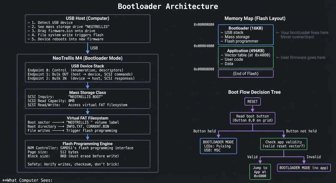 $ lsusb
Bus 001 Device 042: ID 239A:0024 Adafruit NeoTrellis Bootloader
$ lsusb
Bus 001 Device 042: ID 239A:0024 Adafruit NeoTrellis Bootloader
$ ls /Volumes/NEOTRELLIS/ INFO.TXT CURRENT.BIN
$ cat /Volumes/NEOTRELLIS/INFO.TXT NeoTrellis M4 Bootloader v1.0 Bare-metal by [You]
Chip: ATSAMD51J19 (512KB Flash, 192KB RAM) Application: Valid (0x4000) Last flash: 2024-12-15 14:32:05
Drag a .BIN file here to flash new firmware.
$ cp my_firmware.bin /Volumes/NEOTRELLIS/
**Serial Debug Output (from bootloader):**
NeoTrellis Bootloader v1.0 Reset reason: External Boot button: HELD Entering bootloader mode…
USB initialization: Device attached Address assigned: 12 Configuration set: 1 Mass Storage Class active
Virtual filesystem: Volume: NEOTRELLIS Total: 8MB, Free: 7.5MB Files: INFO.TXT (512B), CURRENT.BIN (32KB)
SCSI command: INQUIRY SCSI command: READ CAPACITY (16MB, 512B sectors) SCSI command: READ(10) sector 0 (boot sector) SCSI command: READ(10) sector 1-32 (FAT)
File write detected: FIRMWARE.BIN (48KB) Verifying file… File valid (ARM reset vector detected)
Erasing application space… Block 0 (0x4000): Erased Block 1 (0x6000): Erased … Block 5 (0xE000): Erased
Programming… Page 0: Written, verified OK Page 1: Written, verified OK … Page 95: Written, verified OK
Flash complete! (48KB in 1.2 seconds) Checksum: 0x3A7F valid
Rebooting into new firmware…
---
##### Observable Behavior & Validation
- **UF2 drag‑and‑drop** triggers automatic reboot into the new firmware.
- **Recovery path** works if app firmware is invalid.
Example serial output:
```text
[BOOT] usb_msc mounted
[BOOT] flash_ok rebooting...
The Core Question You’re Answering
“How does a device program itself, and how do you implement USB mass storage from scratch to enable it?”
This is the deepest question in embedded systems. The bootloader is the foundation—the code that can never be corrupted because it’s the only code that can recover from a bad flash. Understanding this means you can build any embedded product.
Concepts You Must Understand First
Stop and research these before coding:
- USB Fundamentals
- What are USB endpoints? (Control, Bulk, Interrupt, Isochronous)
- What happens during enumeration?
- What are descriptors? (Device, Configuration, Interface, Endpoint)
- Book Reference: “USB Complete” Ch. 1-5
- USB Mass Storage Class
- What’s Bulk-Only Transport (BOT)?
- What SCSI commands must you implement? (Inquiry, ReadCapacity, Read10, Write10)
- What’s the Command/Status Wrapper?
- Book Reference: “USB Complete” Ch. 9
- FAT Filesystem
- What’s in the boot sector?
- How does the FAT table work?
- What’s a directory entry format?
- Book Reference: “Practical File System Design” Ch. 2
- SAMD51 Flash (NVM)
- What’s the page size? Block size?
- How do you unlock flash for writing?
- What’s the write sequence? (Erase block, write page)
- Book Reference: SAMD51 Datasheet - NVM Controller
- Bootloader Design
- Where does the bootloader live in memory?
- How do you jump to application code?
- How do you determine if application is valid?
- Book Reference: “Making Embedded Systems” Ch. 6
Spec Anchor: UF2 firmware for M4 boards must start at 0x4000 because the bootloader occupies the first 16 KB; linker scripts must respect this. Source: https://learn.adafruit.com/adafruit-uf2-bootloader-details/uf2-format
Questions to Guide Your Design
Before implementing, think through these:
- USB Stack
- Will you write USB from scratch or use TinyUSB?
- How do you handle enumeration?
- How do you handle USB suspend/resume?
- Virtual Filesystem
- Do you implement a real FAT or fake it?
- How do you detect file writes? (Monitor specific sectors)
- What happens if user writes non-firmware file?
- Flash Safety
- How do you ensure bootloader is never overwritten?
- What if power fails during flash?
- How do you verify the new firmware before rebooting?
- User Experience
- How does user enter bootloader mode?
- What visual feedback during flashing?
- How long should flashing take? (Target: < 5 seconds)
Thinking Exercise
Design the Flash Update Protocol
Before coding, design the protocol for safe firmware updates:
Problem: You're running code from flash while trying to write to flash.
Solution: Execute critical code from RAM.
Flash Write Sequence:
1. Receive file data over USB into RAM buffer
2. Validate:
- File size < application space
- First word looks like valid reset vector (0x20000000-0x20030000)
- Optional: Check for magic bytes or checksum
3. Disable interrupts
4. Copy flash_write_page() function to RAM
5. Call RAM-resident function to:
a. Erase block (8KB)
b. Write pages (512B each) with verification
c. Repeat for all blocks
6. Verify entire image
7. Write "valid" marker
8. Reset (NVIC_SystemReset)
Recovery:
- If flash fails, bootloader still works (never overwritten)
- If app is corrupt, bootloader detects and stays in bootloader mode
- User can always re-flash
Questions:
- Why must flash_write_page() be in RAM?
- What’s the “valid marker” and where do you store it?
- How do you handle a file larger than the buffer?
The Interview Questions They’ll Ask
-
“Walk me through USB enumeration. What descriptors are exchanged?”
-
“Explain the FAT filesystem boot sector. What fields are critical for a minimal implementation?”
-
“Why is the bootloader stored at address 0x0 and not the application?”
-
“How do you safely program flash from code running on the same flash?”
-
“What happens if power fails mid-flash? How do you recover?”
Hints in Layers
Hint 1: Starting Point Use TinyUSB for the USB stack initially. Get mass storage working with a simple 1-sector “filesystem.” Then either customize TinyUSB or replace it.
Hint 2: Minimal FAT Implementation
// You don't need full FAT - just enough to fool the OS
struct FATBootSector {
uint8_t jump[3];
char oem[8];
uint16_t bytes_per_sector; // 512
uint8_t sectors_per_cluster; // 1
uint16_t reserved_sectors; // 1
uint8_t num_fats; // 1
uint16_t root_entries; // 16
uint16_t total_sectors; // 16384 (8MB)
uint8_t media_type; // 0xF8
uint16_t fat_sectors; // 32
// ... more fields
} __attribute__((packed));
// Return fixed responses for sector reads:
// Sector 0: Boot sector (above)
// Sectors 1-32: FAT table (mostly 0xFF)
// Sector 33+: Root directory + file data
Hint 3: Detect File Write
// Monitor writes to root directory area
void handle_write(uint32_t sector, uint8_t* data) {
if (sector >= ROOT_DIR_SECTOR && sector < ROOT_DIR_SECTOR + ROOT_SECTORS) {
// Check if this is a new file
for (int i = 0; i < 16; i++) { // 16 entries per sector
struct DirEntry* entry = (struct DirEntry*)(data + i * 32);
if (entry->name[0] != 0x00 && entry->name[0] != 0xE5) {
if (ends_with(entry->name, "BIN")) {
start_flash_sequence(entry);
}
}
}
} else if (sector >= DATA_START_SECTOR) {
// This is file data - buffer it for flashing
buffer_firmware_data(sector, data);
}
}
Hint 4: RAM-Resident Flash Write
// This function MUST be copied to and executed from RAM
__attribute__((section(".ramfunc")))
void flash_write_page(uint32_t address, uint8_t* data) {
// Unlock NVM
NVMCTRL->CTRLA.reg = NVMCTRL_CTRLA_CMDEX_KEY | NVMCTRL_CTRLA_CMD_PBC;
while (!NVMCTRL->INTFLAG.bit.READY);
// Write 512 bytes (16 words at a time for SAMD51)
uint32_t* src = (uint32_t*)data;
uint32_t* dst = (uint32_t*)address;
for (int i = 0; i < 128; i++) {
*dst++ = *src++;
}
// Execute write
NVMCTRL->CTRLA.reg = NVMCTRL_CTRLA_CMDEX_KEY | NVMCTRL_CTRLA_CMD_WP;
while (!NVMCTRL->INTFLAG.bit.READY);
}
// Copy function to RAM and call:
memcpy(ram_buffer, flash_write_page, FLASH_WRITE_SIZE);
((void (*)(uint32_t, uint8_t*))ram_buffer)(address, data);
Books That Will Help
| Topic | Book | Chapter |
|---|---|---|
| USB protocol | “USB Complete” by Axelson | Ch. 1-5 |
| Mass Storage Class | “USB Complete” | Ch. 9 |
| FAT filesystem | “Practical File System Design” | Ch. 2 |
| Flash programming | SAMD51 Datasheet | NVM Controller |
| Bootloader design | “Making Embedded Systems” by White | Ch. 6 |
Common Pitfalls & Debugging
| Problem | Cause | Fix | Verification |
|---|---|---|---|
| USB not recognized | Descriptor error | Validate with USB analyzer | Use USBlyzer/Wireshark |
| Drive not mounting | FAT format error | Fix boot sector fields | Compare with real FAT |
| Flash write fails | Flash locked | Unlock with security bit | Check NVM STATUS |
| Device bricks | Bad app vector | Add validity check in bootloader | Test with invalid file |
| Slow flashing | Page-by-page writes | Use block writes | Profile with timer |
Advanced Pitfalls
- Bricking risk if you overwrite the bootloader region.
- Power loss during flash can corrupt the app image.
Learning Milestones
- USB enumerates → Basic USB stack working
- Drive mounts → Mass storage + FAT working
- File writes detected → Virtual filesystem parsing
- Flash programming works → NVM controller mastered
- Full bootloader → Complete self-programming system
PROJECT COMPARISON TABLE
| # | Project | Tier | Difficulty | Time | Coolness | Business | Key Learning |
|---|---|---|---|---|---|---|---|
| 1 | Interactive Button-LED Matrix | CircuitPython | Beginner | Weekend | Level 3 | Resume Gold | GPIO, NeoPixels basics |
| 2 | RGB Color Mixer | CircuitPython | Beginner | Weekend | Level 3 | Resume Gold | Color spaces, animation |
| 3 | Accelerometer Light Show | CircuitPython | Intermediate | 1 week | Level 4 | Resume Gold | I2C sensors, motion |
| 4 | USB MIDI Controller | CircuitPython | Intermediate | 1-2 weeks | Level 4 | Micro-SaaS | USB protocols, MIDI |
| 5 | Precision Timer | CircuitPython | Intermediate | 1 week | Level 3 | Resume Gold | Low-level timing |
| 6 | Polyphonic Synthesizer | Arduino | Advanced | 2-3 weeks | Level 5 | Micro-SaaS | DSP, audio synthesis |
| 7 | Drum Machine Sequencer | Arduino | Intermediate | 1-2 weeks | Level 4 | Micro-SaaS | Sequencing, timing |
| 8 | FFT Spectrum Analyzer | Arduino | Advanced | 2-3 weeks | Level 5 | Resume Gold | FFT, DSP theory |
| 9 | Sample Player with Effects | Arduino | Advanced | 2-3 weeks | Level 4 | Micro-SaaS | Audio effects, routing |
| 10 | Capacitive Theremin | Arduino | Advanced | 2-3 weeks | Level 5 | Micro-SaaS | Capacitive sensing |
| 11 | Bare-Metal Blinker | Bare-Metal C | Beginner | 1 week | Level 4 | Resume Gold | Startup code, registers |
| 12 | Bare-Metal NeoPixels | Bare-Metal C | Intermediate | 2 weeks | Level 4 | Resume Gold | DMA, SPI, timing |
| 13 | Bare-Metal UART | Bare-Metal C | Intermediate | 1-2 weeks | Level 4 | Resume Gold | Serial protocols |
| 14 | Bare-Metal DAC Audio | Bare-Metal C | Advanced | 3-4 weeks | Level 5 | Resume Gold | Audio output, DMA |
| 15 | Bare-Metal I2C Driver | Bare-Metal C | Advanced | 2-3 weeks | Level 4 | Resume Gold | I2C protocol |
| 16 | Complete DAW Controller | Integration | Expert | 4-6 weeks | Level 5 | Open Core | Full MIDI integration |
| 17 | Audio Visualizer + Display | Integration | Master | 6-8 weeks | Level 5 | Micro-SaaS | Complete DSP system |
| 18 | USB Bootloader | Integration | Master | 8-12 weeks | Level 5 | Disruptor | Complete USB stack |
RECOMMENDED LEARNING PATHS
Path 1: Music Producer (Fastest to Fun)
Goal: Create usable music tools as quickly as possible Timeline: 4-6 weeks Projects: 4 → 7 → 6 → 9 → 16
- Start with MIDI controller (instant DAW integration)
- Build drum machine for beat-making
- Add synthesizer for melodic content
- Combine with sample player
- Graduate to complete DAW controller
Path 2: Audio Engineer (DSP Focus)
Goal: Deep understanding of digital signal processing Timeline: 8-12 weeks Projects: 6 → 8 → 9 → 14 → 17
- Learn synthesis fundamentals
- Master FFT and frequency domain
- Implement audio effects
- Build bare-metal DAC output
- Create complete visualizer system
Path 3: Systems Programmer (Hardware Mastery)
Goal: Complete understanding from registers to USB Timeline: 12-16 weeks Projects: 11 → 12 → 13 → 14 → 15 → 18
- Start with bare-metal basics
- Master peripherals one by one
- Build complete I/O ecosystem
- Graduate to USB bootloader
Path 4: Complete Mastery (All 18 Projects)
Goal: Professional embedded engineer level Timeline: 20-30 weeks (5-7 months) Order: 1 → 2 → 3 → 4 → 5 → 11 → 12 → 13 → 6 → 7 → 8 → 14 → 15 → 9 → 10 → 16 → 17 → 18
- CircuitPython foundation
- Transition to bare-metal basics
- Add Arduino audio
- Complete bare-metal peripherals
- Advanced audio projects
- Integration projects
FINAL PROJECT: The Ultimate NeoTrellis (Combines Everything)
After completing all 18 projects, challenge yourself with this capstone:
Build a standalone groovebox that rivals commercial products:
- Bare-metal core - No libraries, pure register programming
- Polyphonic synthesis - 8 voices with waveform selection
- Drum machine - 16-step sequencer with sample playback
- Effects chain - Delay, reverb, filter with accelerometer control
- USB MIDI - Full bidirectional integration with DAW
- SD card storage - Save/load patterns and samples
- Custom bootloader - Drag-drop firmware updates
This project uses every concept from every project: USB stacks, audio synthesis, file systems, DMA, sensors, and real-time processing—all running simultaneously on a single $55 board.
SUMMARY
This learning path covers the NeoTrellis M4 through 18 comprehensive projects across 4 tiers of complexity.
All Projects at a Glance
| # | Project Name | Main Language | Difficulty | Time Estimate |
|---|---|---|---|---|
| 1 | Interactive Button-LED Matrix | CircuitPython | Beginner | Weekend |
| 2 | RGB Color Mixer Instrument | CircuitPython | Beginner | Weekend |
| 3 | Accelerometer Light Show | CircuitPython | Intermediate | 1 week |
| 4 | USB MIDI Controller | CircuitPython | Intermediate | 1-2 weeks |
| 5 | Precision Timer/Metronome | CircuitPython | Intermediate | 1 week |
| 6 | Polyphonic Synthesizer | Arduino C++ | Advanced | 2-3 weeks |
| 7 | 8-Step Drum Machine | Arduino C++ | Intermediate | 1-2 weeks |
| 8 | FFT Spectrum Analyzer | Arduino C++ | Advanced | 2-3 weeks |
| 9 | Sample Player with Effects | Arduino C++ | Advanced | 2-3 weeks |
| 10 | Capacitive Theremin | Arduino C++ | Advanced | 2-3 weeks |
| 11 | Bare-Metal LED Blinker | C | Beginner | 1 week |
| 12 | Bare-Metal NeoPixel Driver | C | Intermediate | 2 weeks |
| 13 | Bare-Metal UART Console | C | Intermediate | 1-2 weeks |
| 14 | Bare-Metal DAC Audio | C | Advanced | 3-4 weeks |
| 15 | Bare-Metal I2C Driver | C | Advanced | 2-3 weeks |
| 16 | Complete DAW Controller | Arduino/C | Expert | 4-6 weeks |
| 17 | Audio Visualizer + Display | C | Master | 6-8 weeks |
| 18 | USB Mass Storage Bootloader | C | Master | 8-12 weeks |
Expected Outcomes
After completing these projects, you will:
- Understand CircuitPython for rapid prototyping and USB device development
- Master Arduino’s audio ecosystem for professional synthesizer and sequencer development
- Program bare-metal C with complete understanding of SAMD51 peripherals
- Implement USB protocols from mass storage to MIDI
- Design real-time systems balancing multiple time-critical tasks
- Build production-quality tools that rival commercial products
- Debug at every level from register bits to USB packets
- Read any datasheet and implement any peripheral
You’ll have built 18 working projects that demonstrate deep understanding of embedded systems—from blinking an LED to writing your own USB bootloader. This is the difference between following tutorials and truly mastering embedded development.
Total estimated time: 40-60 weeks for all projects (can be done selectively in 8-16 weeks)
Remember: The goal isn’t to complete every project—it’s to deeply understand the concepts each one teaches. Pick the path that matches your interests, and build until you truly understand.
Advanced Scope Extension (Added 2026-02-12)
This addendum expands the original NeoTrellis M4 sprint into professional embedded systems territory. It explicitly adds the missing depth requested for real-time scheduling discipline, advanced DSP implementation, USB stack internals, memory architecture control, power engineering, hardware bus expansion, and production firmware practices.
This extension is intentionally append-only so the original learning path remains intact. If you already completed Projects 1-18, you can treat Projects 19-25 as a Pro Track that upgrades your skillset from “advanced maker” to “junior firmware engineer” and then to “systems-focused embedded engineer.”
Primary references used for this addendum (official docs first):
- ARM Cortex-M4 Technical Reference Manual
- CMSIS-Core NVIC API Reference
- CMSIS-DSP Library
- CMSIS-DSP Filtering Functions
- TinyUSB Documentation
- TinyUSB Concurrency Model
- TinyUSB Device Stack
- USB 2.0 Specification (USB-IF)
- MIDI 2.0 Specifications
- Microchip ATSAMD51J19 Product Page / Datasheet Entry
Theory Primer Addendum: Pro Systems Topics
Chapter 9: Real-Time Systems Design (Deterministic Control Path)
Fundamentals
Real-time embedded design is not about raw speed; it is about bounded behavior under load. On NeoTrellis M4, the key challenge is guaranteeing that musical events, LED updates, sensor reads, and USB transfers all happen within explicit deadlines. If your interrupt latency spikes unpredictably, timing-sensitive tasks like MIDI clock generation, sequencer stepping, and audio scheduling degrade immediately. The NVIC (Nested Vectored Interrupt Controller) gives you programmable interrupt priorities and preemption behavior; that is your first lever for deterministic design. Your second lever is architecture: separating hard real-time work in ISRs from soft real-time work in the main loop. Your third lever is queue design: using lock-free single-producer/single-consumer queues to move events safely without blocking. Determinism comes from budgeted worst-case execution time (WCET), measured latency histograms, and deliberate overload handling policies.
Deep Dive
The most common embedded failure mode in music controllers is accidental priority inversion by design, not by RTOS mutex. Example: a medium-priority LED animation ISR runs too long, delaying a high-importance MIDI edge capture ISR because global interrupts were disabled in a “quick” critical section. The fix is not “optimize later”; the fix is architecture-first scheduling. Start by classifying tasks:
- Hard real-time: audio buffer refill deadlines, MIDI clock edges, USB endpoint service windows.
- Firm real-time: pad scan sampling, sequencer step transitions.
- Soft real-time: display refresh, debug logging, non-critical UI effects.
Then assign interrupt priorities so hard real-time tasks can preempt lower classes. On Cortex-M4, effective implemented priority bits are device-specific; you must verify priority granularity on SAMD51 before assuming full 8-bit priority behavior. Treat every ISR like a micro-kernel: timestamp, copy minimal state, enqueue event, exit. Do not parse complex state machines or run floating DSP in long ISRs unless there is no alternative.
Latency measurement must be built into your firmware, not inferred from feel. Use cycle counters or high-resolution timer capture to measure:
- ISR entry latency (event edge to first instruction in handler)
- ISR execution time
- Time from ISR enqueue to main-loop dequeue
- End-to-end event latency (pad press to MIDI packet transmitted)
Store these metrics in fixed-size ring buffers and report percentile summaries (P50/P90/P99/max). Average latency is almost useless for real-time quality; jitter tails are what users hear as timing “flam” or “slop.”
Deterministic timing guarantees require budget accounting. Build a per-period budget table. For a 1 kHz control tick (1 ms frame), if worst-case sum of highest-priority periodic jobs exceeds ~70-80% of the slot, you are already in risk territory once asynchronous bursts arrive. Add explicit degradation rules: drop LED frame rate first, then reduce logging verbosity, then disable nonessential UI animations. Never let overload silently impact audio/MIDI critical paths.
ISR vs main loop tradeoff is straightforward in principle:
- ISR: minimal, bounded, immediate response, no dynamic allocation, no blocking.
- Main loop/task context: heavy compute, state machines, formatting, retries.
Lock-free event queues are ideal for this split. For single ISR producer and single main consumer, a power-of-two ring buffer with atomic head/tail updates avoids locks and keeps bounded O(1) behavior. Define overflow policy explicitly (drop newest, drop oldest, or set fault flag). For musical controls, “drop oldest control-change flood but keep note-on/off” is often preferable.
Finally, validate determinism under stress, not idle. Run a stress profile: maximum pad mashing, active USB traffic, full LED animation, sensor fusion enabled, and audio engine loaded. If P99 latency still remains within your target window and max jitter stays bounded, your design is production-credible.
Mental Model Diagram
Physical Event --> EIC IRQ --> NVIC arbitration --> ISR (timestamp + enqueue)
| |
| +--> ring buffer write (O(1))
v
Higher-priority preemption
|
Main loop scheduler <--------------------+
| drains queue
| updates state machine
| schedules USB/MIDI/audio jobs
v
Observable output (MIDI packet, LED frame, DAC update)
Key invariant: ISR never blocks, queue operations are bounded, and deadlines are measured.
How This Fits on Projects
- Project 19 introduces hard metrics: latency, jitter, queue overflow behavior.
- Project 20 uses deterministic scheduling for DSP block processing.
- Project 21 validates endpoint service timing under USB load.
- Project 25 applies the same discipline to watchdog-safe production firmware.
Minimal Concrete Example (Pseudocode)
on_irq_pad_edge():
t0_cycles = read_cycle_counter()
evt = {type: PAD_EDGE, ts: t0_cycles, key: read_key_id()}
if ring_is_full():
overflow_counter += 1
else:
ring_push(evt)
irq_cycles_histogram_add(read_cycle_counter() - t0_cycles)
return
main_loop():
while ring_has_item():
evt = ring_pop()
dispatch_state_machine(evt)
run_soft_tasks_if_budget_remaining()
Common Misconceptions
- “High clock speed guarantees low latency.” Wrong: unbounded ISRs still break deadlines.
- “Average loop time is enough.” Wrong: jitter tails define user experience.
- “Disabling interrupts briefly is harmless.” Wrong: repeated micro-stalls create macro-jitter.
References
- ARM Cortex-M4 Technical Reference Manual
- CMSIS-Core NVIC API
- [Making Embedded Systems (2nd ed.) - Interrupts and Timing chapters]
Chapter 10: Advanced Audio / DSP on Cortex-M4F
Fundamentals
The ATSAMD51 Cortex-M4F is capable of serious embedded DSP when you architect dataflow around block processing and DMA. The core ideas are: represent audio as fixed-size sample buffers; process each block before the playback deadline; and avoid sample-by-sample dynamic behavior that explodes CPU cost. CMSIS-DSP provides optimized math kernels (FIR, biquad IIR, FFT, vector ops) that use ARM-friendly memory access patterns and SIMD/FPU where available. Fixed-point and floating-point both matter: float is easier to reason about and tune, while fixed-point can reduce CPU and memory costs in constrained paths. For musical firmware, envelope generators, voice allocation, and buffer scheduling are just as important as oscillator quality.
Deep Dive
At 48 kHz sample rate with 128-sample blocks, your engine has 2.667 ms to complete every audio block. Miss once and users hear a click. That deadline defines architecture more than any library choice. Start with a double-buffered DMA pipeline: while DMA plays buffer A, CPU renders buffer B. On half/full-transfer interrupts, swap roles predictably. This gives deterministic scheduling windows and isolates timing from main loop jitter.
CMSIS-DSP kernels should be selected per stage. FIR filters are stable and linear-phase (good for some EQ and smoothing) but can be CPU-heavy for long taps. IIR biquads are much cheaper and common for tone shaping, but coefficient tuning and numerical stability matter more. On M4F, single-precision float often provides enough throughput for moderate polyphony, especially if you avoid transcendental functions inside inner loops. For higher voice counts, mixed precision is practical: oscillator phase and envelope in float, final mix or control paths in q15/q31 where needed.
Envelope generators (ADSR) are frequently underestimated. Abrupt amplitude changes cause clicks because waveform discontinuities add broadband energy. Implement minimum attack/release slopes and update envelopes at audio rate or at a high enough control rate with interpolation. Voice management is equally critical: define deterministic voice stealing (oldest, quietest, or release-state first) and keep per-voice state compact to improve cache/locality behavior.
Buffer scheduling strategy governs glitch resilience:
- Single buffer: unacceptable for dynamic workloads.
- Double buffer: baseline for reliable real-time audio.
- Triple buffer: higher latency, but better burst tolerance.
For performance, instrument every block with timing markers and publish over UART/USB logs in low-rate summarized form. If block processing P99 exceeds ~70-80% of block deadline, optimize before adding features. Common wins: table-lookup oscillators, precomputed envelopes, reducing denormals, minimizing branchy code inside sample loops, and batching parameter updates per block.
DMA-driven DAC output removes per-sample ISR burden. Instead of writing DAC registers in tight timer interrupts, let timer-triggered DMA move samples directly. CPU then focuses on synthesis and control. This shift usually determines whether a design supports 4 voices or 16+ voices on the same hardware budget.
Finally, design for musical correctness, not only numerical correctness. Verify pitch stability across octaves, envelope repeatability, and click-free note transitions. A “technically fast” engine that produces unstable tuning or zipper noise is not production quality.
Mental Model Diagram
MIDI/Event Queue --> Voice Manager --> Oscillators --> Filter Stage --> Mix --> Limiter --> DMA Buffer
| | | |
| | +--> CMSIS-DSP FIR/IIR |
+--> ADSR env ----+ |
v
Timer trigger -> DAC via DMA
Invariant: CPU finishes next buffer before DMA consumes current buffer.
How This Fits on Projects
- Project 20 is the primary DSP chapter application.
- Project 24 reuses DMA and buffer design with external I2S codecs.
- Project 25 integrates runtime profiling and safe degradation policies.
Minimal Concrete Example (Pseudocode)
for each audio_block:
for each active_voice:
osc = wavetable_lookup(voice.phase)
env = adsr_step(voice.env)
sample += osc * env
voice.phase += phase_inc
sample = biquad_process(sample)
out_block[n] = soft_clip(sample)
swap_double_buffer_when_dma_half_or_full_irq()
Common Misconceptions
- “FFT visualizer equals audio engine mastery.” Wrong: rendering and synthesis constraints differ.
- “Float is always too slow on MCU.” Wrong on M4F for many real workloads.
- “No clicks means stable engine.” Not enough; also validate CPU margin and jitter.
References
Chapter 11: USB Stack Internals (TinyUSB and Composite Devices)
Fundamentals
Class-compliant USB MIDI is only the entry point. Professional controller firmware often needs composite USB behavior: MIDI + HID + vendor-specific channels in one device. To do this safely, you must understand descriptors, endpoint types, polling intervals, and control transfer behavior. TinyUSB abstracts many details but does not eliminate architectural responsibility. Endpoint allocation, callback timing, and task/ISR boundaries still define correctness.
Deep Dive
USB device bring-up has three layers: physical link timing, protocol control flow, and class behavior. Enumeration starts with reset, then descriptor discovery via endpoint 0 control transfers. If your device descriptor, configuration descriptor, interface descriptors, or endpoint descriptors are inconsistent, hosts may partially enumerate and fail silently at class binding.
Composite devices introduce interface association complexity. You must ensure each function has coherent interface numbers and endpoint assignments without collisions. For MIDI + HID, host stacks typically tolerate this well when descriptors are standards-compliant, but subtle mistakes (wrong total length field, malformed report descriptor, endpoint max packet mismatch) produce hard-to-debug behavior.
TinyUSB’s concurrency model matters: some APIs are safe only in task context, while callbacks may run in interrupt context depending on backend and configuration. Keep callback work minimal; enqueue class events and process them in main context similarly to ISR design elsewhere. Treat USB callbacks as real-time control points with strict execution budgets.
Low-level endpoint management becomes critical under burst traffic. MIDI event packets are small but frequent. HID reports are periodic. Vendor endpoints may be bursty. If endpoint FIFOs are not serviced predictably, NAK storms and perceived latency spikes appear. Instrument endpoint queue depth and service latency like any other timing-critical subsystem.
Custom descriptors unlock product differentiation:
- Multiple MIDI cable numbers for logical routing
- HID pages for transport controls (play/stop/record)
- Vendor interface for firmware config or diagnostics
But every custom descriptor increases test matrix across OSes. Build a descriptor validation checklist and test on at least macOS, Windows, and Linux with explicit enumeration logs.
Mental Model Diagram
Host USB Stack
|
| Control Transfers (EP0): GET_DESCRIPTOR / SET_CONFIGURATION
v
Device Descriptor Parser --> Configuration --> Interfaces --> Endpoints
| |
| +--> MIDI IN/OUT bulk or interrupt
+--> HID report endpoint
TinyUSB callbacks --> event queue --> main loop class handlers
Invariant: descriptor coherence and bounded callback time.
How This Fits on Projects
- Project 21 is the main implementation target for this chapter.
- Project 25 uses vendor endpoints for config and diagnostics.
Minimal Concrete Example (Descriptor Transcript)
Host: GET_DESCRIPTOR(Device)
Device: VID=0x239A PID=0x80XX Class=0 (composite)
Host: GET_DESCRIPTOR(Configuration)
Device: Interface0=MIDI, Interface1=HID, Interface2=Vendor
Host: SET_CONFIGURATION(1)
Device: Endpoints armed (EP1 OUT MIDI, EP2 IN MIDI, EP3 IN HID, EP4 OUT Vendor)
Common Misconceptions
- “Class-compliant means no testing needed.” Wrong: descriptor bugs are common.
- “TinyUSB handles all timing.” Wrong: your callbacks and queueing still matter.
- “Composite is just adding one extra descriptor block.” Wrong: it changes host binding behavior.
References
- TinyUSB Documentation
- TinyUSB Device Stack
- TinyUSB Concurrency
- USB 2.0 Specification
- MIDI 2.0 Specifications
Chapter 12: Memory Architecture and Optimization
Fundamentals
Embedded memory mastery means controlling where bytes live, how long they live, and what happens when they run out. On ATSAMD51, practical decisions include SRAM region planning, stack headroom guarantees, heap policy, linker script layout, and flash write lifecycle. Many hobby projects fail in the field not because algorithms are wrong, but because memory behavior is unbounded.
Deep Dive
Start with a memory ownership map. Divide SRAM usage into: static data/BSS, audio buffers, event queues, stack, and optional heap. If you cannot answer “what is my worst-case stack depth?” you do not have a production-ready firmware image. Add high-water marks for stack and heap, sampled at runtime and exported in diagnostics.
Linker scripts are not “build trivia”; they are architectural contracts. Place latency-critical buffers in fast internal SRAM, isolate DMA buffers with alignment guarantees, and reserve explicit crash-log regions. If your bootloader and app coexist, define immutable boundaries and integrity checks before jumps.
Fragmentation analysis is mandatory when dynamic allocation is used in long-running firmware. Even if average free memory looks healthy, allocation failure can occur due to fragmentation topology. For real-time paths, prefer fixed pools or arena allocators over general-purpose heap alloc/free patterns.
Flash wear considerations shape configuration strategy. Never rewrite the same flash page on every small settings change. Use versioned records, append-only log pages, and compaction routines with wear distribution. Pair this with brownout-safe commit protocols (write new record, verify CRC, then mark active) to prevent partial-write corruption.
RAM profiling should include both static and temporal components:
- Static map from linker output (section sizes)
- Runtime max utilization under stress scenarios
- Buffer occupancy histograms for queue-backed subsystems
Without this, “it fits” is a guess. With this, memory budgets become enforceable engineering constraints.
Mental Model Diagram
Flash Layout:
[ Bootloader ][ App Image A ][ App Image B/Spare ][ Config Log Pages ]
SRAM Layout (conceptual):
[ .data/.bss ][ DMA buffers ][ audio scratch ][ event queues ][ heap? ][ stack↓ ]
Invariant: hard real-time paths avoid fragmented heap dependencies.
How This Fits on Projects
- Project 22 is the dedicated memory-architecture lab.
- Project 25 consumes its results for production-safe config and crash logs.
Minimal Concrete Example (Memory Budget Table)
Section Budget Peak (stress) Margin
.data + .bss 26 KB 26 KB fixed
audio buffers 48 KB 42 KB +6 KB
event queues 8 KB 5.2 KB +2.8 KB
stack 24 KB 17.5 KB +6.5 KB
heap 16 KB 7 KB +9 KB
Total SRAM 192 KB 97.7 KB +94.3 KB
Common Misconceptions
- “No crash means memory is fine.” Wrong: latent overflow can be load-dependent.
- “Heap usage is okay if malloc succeeds at boot.” Wrong: fragmentation grows over time.
- “Linker script is only for startup engineers.” Wrong: it controls system reliability.
References
Chapter 13: Power Engineering for Portable Controllers
Fundamentals
Portable embedded design requires power states, not just firmware features. To move from desk prototype to deployable instrument, you must control sleep modes, dynamic clocking, peripheral gating, wake sources, and battery safety behavior. The critical question is not “does it run,” but “how long, how safely, and how predictably does it run off battery under real workloads?”
Deep Dive
Power is a systems budget like CPU time. Start with current profiles per mode: active play, idle UI, deep idle, USB-connected charging/operation. Measure, do not estimate. Use a power monitor and log current over time while triggering real user scenarios.
Clock scaling can reduce dynamic power significantly but can also destabilize timing assumptions if not designed carefully. Define timing domains: keep time-critical audio/control clocks stable while scaling noncritical domains during idle windows. Peripheral gating is often the largest easy win: disable ADC, SERCOM, display backlight, and sensor polling when not needed.
Sleep modes must be tied to wake policy. If wake-on-pad and wake-on-USB are required, ensure those interrupt sources are configured and tested across brownout/reset boundaries. A common bug is entering low power with one subsystem still DMA-active, causing unexpected wakes or partial lockups.
Battery chemistry considerations affect firmware policy:
- LiPo: requires undervoltage thresholds, safe charge handling external to MCU but observed by firmware.
- Alkaline/NiMH packs: wider voltage sag behavior, different low-voltage cutoff strategy.
Brownout detection is not optional for reliability. Configure BOD threshold and reset behavior intentionally. Then test power-fail scenarios by controlled voltage drops while flash writes or config commits are active.
The metric that matters for user trust is predictable runtime with graceful degradation. If battery drops, reduce LED brightness, lower display refresh, and disable nonessential visual effects before audio/control quality degrades.
Mental Model Diagram
Battery --> Regulator --> MCU + Peripherals
| |
| +--> Active mode (full clock, full features)
| +--> Idle mode (reduced clocks, gated peripherals)
| +--> Deep sleep (wake on GPIO/USB/RTC)
|
+--> Voltage monitor/BOD --> safe shutdown or reset path
Invariant: no flash/config write without power-fail-safe commit sequence.
How This Fits on Projects
- Project 23 is the primary low-power implementation.
- Project 25 uses brownout-aware config and fault policy.
Minimal Concrete Example (Mode Policy)
if usb_present:
run_full_performance_profile()
else if no_input_for_5s:
lower_core_clock(); dim_leds(); stop_display_dma()
else if no_input_for_60s:
enter_standby_with_wake_on_key_and_rtc()
Common Misconceptions
- “Sleep mode alone solves battery life.” Wrong: leaks often come from active peripherals.
- “Average current is enough.” Wrong: peak/current transients affect stability.
- “Brownout is a hardware-only issue.” Wrong: firmware commit policy is critical.
References
Chapter 14: Hardware-Level Expansion (I2C, SPI, I2S, ADC)
Fundamentals
The NeoTrellis M4 becomes significantly more capable when you treat it as a controller hub rather than a fixed board. Expansion buses let you add high-refresh SPI displays, external ADCs for better analog front ends, IMU-based sensor fusion, and I2S codecs for improved audio quality. The challenge shifts from single-peripheral coding to multi-bus scheduling and contention control.
Deep Dive
SPI display performance depends on transfer strategy and command framing. Blocking pixel writes saturate CPU and cause control lag. DMA SPI transfers with tiled frame updates are the practical path: precompute dirty regions, enqueue DMA bursts, and keep UI update rates adaptive to system load.
Sensor fusion on accelerometer + gyro (if external IMU added) introduces timing and calibration demands. Fuse only after time-synchronizing sensor samples and validating bias/noise profiles. For musical controllers, low-latency orientation estimates are useful, but stable filtering matters more than high raw sample rates.
External ADC integration is valuable when onboard ADC noise, channel count, or sampling behavior is insufficient. But adding ADC over SPI/I2C changes timing budget and data freshness guarantees. Treat acquisition as periodic tasks with explicit deadlines and buffering.
I2S audio codecs can outperform simple DAC paths for certain use cases. They support higher-fidelity stereo paths and often provide clocking roles (master/slave) that must be configured deliberately. Misconfigured clock domain relationships are a top source of pops, drift, and periodic glitches.
A production-grade expansion design needs bus arbitration policy. Define priority for audio/control buses vs display telemetry. During overload, display updates should degrade first.
Mental Model Diagram
NeoTrellis M4 (ATSAMD51)
-----------------------------------------------------
| SPI (DMA) --> TFT/OLED display (dirty-region blits)
| I2C --> sensors (IMU, env, knobs expander)
| I2S --> external codec (stereo in/out)
| SPI/I2C --> external ADC for control voltages
-----------------------------------------------------
| shared CPU + DMA + interrupt budget |
Invariant: bus tasks have explicit priorities and fallback behavior.
How This Fits on Projects
- Project 24 is the dedicated expansion project.
- Project 25 operationalizes expansion under production fault policies.
Minimal Concrete Example (Scheduling Policy)
every 1 ms: run control scan (highest)
every 2.67 ms: audio block render + I2S refill
every 16.6 ms: display DMA for dirty regions only
every 10 ms: sensor fusion update
Common Misconceptions
- “More buses means linear feature gain.” Wrong: contention and timing complexity grow faster.
- “Display FPS is always user-visible value.” Wrong: control/audio latency dominates perceived quality.
References
Chapter 15: Production-Level Firmware Practices
Fundamentals
Production firmware is designed for failure handling, observability, and upgradeability. It is not enough to work in a lab demo. You need clear state machine architecture, versioned configuration with migration rules, structured logging, watchdog recovery strategy, and a boot/update pipeline with rollback considerations.
Deep Dive
State machine architecture should be explicit and auditable. Hidden state spread across callback flags causes race conditions and field-only bugs. Use defined states, events, transitions, and guard conditions. Separate control-plane state (mode, transport, armed status) from data-plane state (buffer positions, voice tables).
Configuration must be versioned from day one. Even if your initial settings are tiny, future firmware changes will require migration. Store config records with {version, length, crc, payload} and provide deterministic migration steps from N to N+1. Never assume you can reinterpret old bytes safely.
Logging should be structured, rate-limited, and low-overhead. Text logs are useful during development but expensive in real-time paths. Prefer event IDs + compact payloads in ring buffers, with optional host-side decoding. Keep crash-safe breadcrumbs in reserved memory across reset to diagnose watchdog and hard-fault events.
Watchdog strategy should match fault model. A watchdog that resets every lockup but erases root-cause evidence is only partially useful. Pair watchdog with crash context capture and boot-time fault counters to detect reset loops. Escalation policy can disable risky features after repeated failures.
Bootloader customization requires strict image validation and fail-safe behavior. Validate vector table range, image CRC/hash, and optional signature policy before jump. For OTA feasibility, even theoretical planning should define staging area, atomic swap strategy, and rollback triggers. If full OTA is not implemented, still design memory layout to make future OTA possible.
Production readiness is mostly discipline: explicit contracts, measured behavior, controlled upgrades, and post-failure visibility.
Mental Model Diagram
[Bootloader]
| validates image + config schema version
v
[Application Runtime]
|-- State machine core
|-- Real-time engine
|-- Structured event logger
|-- Watchdog heartbeat manager
|
+--> On fault: capture crash context -> reset -> bootloader diagnostics path
Invariant: any reset event leaves evidence and a safe restart path.
How This Fits on Projects
- Project 25 is the full production-practice integration lab.
- Pro Tier section extends this into multi-image and OTA-style flows.
Minimal Concrete Example (Config Record Schema)
config_record = {
magic: 0x4E544D34,
version: 3,
payload_length: 96,
payload_crc32: 0xA1B2C3D4,
payload: <serialized settings>
}
Common Misconceptions
- “Watchdog means reliability solved.” Wrong: you need root-cause data and policy.
- “Config migration can wait.” Wrong: delayed migration work causes unsafe hacks later.
- “OTA is only for Wi-Fi products.” Wrong: staged updates and rollback logic still matter.
References
Concept Summary Table (Advanced Addendum)
| Concept Cluster | What You Need to Internalize |
|---|---|
| Real-Time Determinism | Interrupt priority policy, WCET budgeting, latency/jitter percentile analysis, and lock-free ISR→main communication patterns. |
| Advanced DSP Engine Design | CMSIS-DSP kernel selection, block scheduling, voice management, envelopes, fixed vs float tradeoffs, and DMA double buffering. |
| USB Stack Internals | Descriptor correctness, endpoint scheduling, TinyUSB concurrency boundaries, and composite class integration. |
| Memory Architecture Control | SRAM/flash partitioning, linker script layout, stack/heap policy, fragmentation risk, and wear-aware config persistence. |
| Power Engineering | Sleep and clock policies, peripheral gating, current profiling methodology, battery behavior under load, and brownout-safe operation. |
| Hardware Expansion Architecture | DMA SPI display pipelines, I2S codec timing, sensor fusion scheduling, and multi-bus contention management. |
| Production Firmware Discipline | Explicit state machines, versioned config migrations, structured logging, watchdog/crash handling, and boot/update safety. |
Project-to-Concept Map (Advanced Addendum)
| Project | Concepts Applied |
|---|---|
| Project 19: Real-Time Latency and Jitter Profiler | Real-Time Determinism, Lock-Free Event Queues, NVIC Priority Tuning |
| Project 20: CMSIS-DSP Polyphonic Wavetable Engine | Advanced DSP Engine Design, DMA Scheduling, Deterministic Audio Deadlines |
| Project 21: TinyUSB Composite MIDI+HID Controller | USB Stack Internals, Descriptor Engineering, Endpoint Management |
| Project 22: Memory Map, Linker, and Fragmentation Lab | Memory Architecture Control, Flash Wear Strategy, Runtime Profiling |
| Project 23: Ultra-Low-Power Battery MIDI Node | Power Engineering, Brownout Handling, Sleep/Wake Architecture |
| Project 24: I2S Codec + SPI DMA Display + Sensor Fusion Rig | Hardware Expansion Architecture, Multi-Bus Scheduling, DMA Optimization |
| Project 25: Production Firmware Platform | Production Firmware Discipline, Watchdog/Crash Strategy, Config Versioning |
Deep Dive Reading by Concept (Advanced Addendum)
| Concept | Book and Chapter | Why This Matters |
|---|---|---|
| Real-Time Determinism | “Making Embedded Systems, 2nd Ed” by Elecia White - Interrupts, Scheduling, Debugging chapters | Turns timing from guesswork into measurable contracts. |
| NVIC and ISR Architecture | “The Definitive Guide to ARM Cortex-M3 and Cortex-M4 Processors” by Joseph Yiu - NVIC + Exceptions chapters | Gives hard mental models for priority/preemption behavior. |
| DSP on Embedded Targets | “Understanding Digital Signal Processing” by Richard Lyons - FIR/IIR + FFT chapters | Links filter math to implementation decisions on MCUs. |
| Practical Audio Engines | “The Audio Programming Book” by Richard Boulanger - Real-time block processing sections | Helps design buffer-safe, glitch-free audio paths. |
| USB Device Engineering | “USB Complete” by Jan Axelson - Descriptors, Endpoints, Enumeration chapters | Essential for composite MIDI/HID device reliability. |
| Embedded Memory Reliability | “Embedded Systems Architecture” by Tammy Noergaard - Memory and boot architecture chapters | Connects linker/script policy to fault behavior in the field. |
| Production Firmware Patterns | “Design Patterns for Embedded Systems in C” by Bruce Powel Douglass - State machine and architecture patterns | Provides scalable architecture practices for maintainable firmware. |
Project List (Advanced Addendum)
The following projects extend the existing 18-project journey into systems-level embedded engineering.
Project 19: Real-Time Latency and Jitter Profiler (NVIC + Lock-Free Queue)
- File:
LEARN_NEOTRELLIS_M4_DEEP_DIVE.md - Main Programming Language: C (Arduino core + CMSIS register access)
- Alternative Programming Languages: Bare-metal C, Rust embedded (conceptual port)
- Coolness Level: Level 4: The “Whoa, You Built That?”
- Business Potential: 1. The “Resume Gold”
- Difficulty: Level 4: Expert
- Knowledge Area: Real-Time Scheduling, Interrupt Design, Performance Instrumentation
- Software or Tool: Logic analyzer, cycle counter instrumentation, serial metrics exporter
- Main Book: “Making Embedded Systems, 2nd Ed” by Elecia White
- Expanded Project File:
P19-real-time-scheduler-jitter-profiler.md
What you’ll build: A deterministic event pipeline that measures ISR latency, queue delay, and end-to-end response jitter while the board runs realistic mixed workloads.
Why it teaches real-time systems: It turns abstract “low latency” claims into measured evidence and forces you to enforce interrupt priority and budget contracts.
Core challenges you’ll face:
- NVIC priority tuning -> balancing preemption against starvation
- Lock-free queue design -> preserving O(1) behavior under burst load
- Jitter tail reduction -> optimizing P99 and max latency, not just averages
Real World Outcome
You will run a stress profile (simultaneous pad presses, active USB MIDI stream, LED animation, periodic sensor reads) and get a quantitative timing report:
$ neotrellis_rt_profiler --window 15s --stress all
[15.000s] irq_latency_us: p50=7.8 p90=11.2 p99=18.4 max=31.0
[15.000s] queue_delay_us: p50=22.1 p90=44.7 p99=87.9 max=140.3
[15.000s] pad_to_midi_us: p50=410.2 p90=730.6 p99=1188.9 max=1642.4
[15.000s] queue_overflow=0 deadline_miss=0
PASS: Deterministic target met (p99 < 1.2ms, zero deadline misses)
You should also see visible behavior: metronome LEDs stay phase-locked while aggressive button mashing does not produce MIDI timing drift.
The Core Question You’re Answering
“Can this firmware prove deterministic timing under worst-case user behavior, not just idle demos?”
Concepts You Must Understand First
- NVIC Preemption and Priority Levels
- Which interrupts can interrupt which handlers?
- Book Reference: Joseph Yiu, Cortex-M4 NVIC chapters
- Lock-Free Single Producer / Single Consumer Queues
- How do you avoid mutexes and still avoid corruption?
- Book Reference: Embedded architecture pattern chapters
- Latency vs Jitter Metrics
- Why is P99/max more meaningful than average?
- Book Reference: Real-time debugging chapters
Questions to Guide Your Design
- Priority Plan
- Which ISR gets top priority and why?
- What is your starvation prevention strategy?
- Queue Policy
- What happens when the queue is full?
- Which event types can be dropped safely?
- Instrumentation Cost
- How do you measure timing without perturbing timing too much?
Thinking Exercise
Latency Budget Ledger
Write a budget for each stage (IRQ entry, ISR work, queue transit, dispatch, output). Then compute worst-case total and compare with your musical target (e.g., <= 2 ms end-to-end).
The Interview Questions They’ll Ask
- “How do you tune NVIC priorities for mixed audio/UI workloads?”
- “Why can average latency look great while user experience still feels bad?”
- “How would you design an ISR-safe queue without locks?”
- “What metrics prove deterministic timing behavior?”
- “How do you handle overload without breaking critical paths?”
Hints in Layers
Hint 1: Event Taxonomy Split events into hard, firm, and soft real-time classes before assigning priorities.
Hint 2: Keep ISRs tiny Timestamp, enqueue, and exit. Move parsing and formatting out of interrupts.
Hint 3: Ring Buffer Invariant Use power-of-two queue length and monotonic head/tail indices with explicit overflow counters.
Hint 4: Validate with Percentiles Track P50/P90/P99/max for each stage; reject designs that only report averages.
Books That Will Help
| Topic | Book | Chapter |
|---|---|---|
| Real-time scheduling | “Making Embedded Systems, 2nd Ed” | Interrupts + timing chapters |
| NVIC internals | “Definitive Guide to ARM Cortex-M4” | Exceptions/NVIC chapters |
| Embedded architecture | “Design Patterns for Embedded Systems in C” | Event-driven/state chapters |
Common Pitfalls & Debugging
| Problem | Cause | Fix | Quick test |
|---|---|---|---|
| Latency spikes every second | Debug print bursts in control path | Rate-limit/aggregate logs | Disable prints and compare p99 |
| Random queue corruption | Non-atomic head/tail updates | Use SPSC-safe update pattern | Run 10-minute stress + checksum |
| MIDI jitter under LED load | LED update too high priority | Lower LED task priority / throttle frames | Compare jitter with/without LEDs |
Definition of Done
- Measured latency report includes p50/p90/p99/max for at least 3 stages
- Zero queue corruption after 30-minute stress test
- Overload behavior documented and deterministic
- ISR execution time stays within documented budget
Project 20: CMSIS-DSP Polyphonic Wavetable Engine (DMA + Double Buffer DAC)
- File:
LEARN_NEOTRELLIS_M4_DEEP_DIVE.md - Main Programming Language: C++ (Arduino with CMSIS-DSP)
- Alternative Programming Languages: Bare-metal C, C with CMSIS only
- Coolness Level: Level 5: The “WTF, That’s Possible?”
- Business Potential: 2. The “Micro-SaaS” (firmware IP / instrument engines)
- Difficulty: Level 5: Master
- Knowledge Area: DSP, Audio Scheduling, Polyphonic Voice Management
- Software or Tool: CMSIS-DSP, audio analyzer, logic analyzer for buffer timing
- Main Book: “Understanding Digital Signal Processing” by Richard Lyons
- Expanded Project File:
P20-cmsis-dsp-polyphonic-wavetable-engine.md
What you’ll build: A polyphonic wavetable synthesizer engine with ADSR envelopes, FIR/IIR tone shaping, and deterministic DMA-driven double-buffer playback.
Why it teaches advanced audio: You must coordinate CMSIS-DSP compute, buffer deadlines, and voice allocation policies under strict real-time constraints.
Core challenges you’ll face:
- Buffer scheduling -> ensuring render completion before DMA deadline
- FIR vs IIR tradeoffs -> quality vs CPU budget
- Voice stealing policy -> musical quality under polyphony limits
Real World Outcome
$ neotrellis_synth --voices 12 --rate 48000 --block 128 --profile 20s
[20.000s] audio_deadline_ms=2.667
[20.000s] render_time_ms: p50=0.94 p90=1.31 p99=1.72 max=2.01
[20.000s] active_voices_peak=12 voice_steals=37
[20.000s] dsp_cpu_load_avg=48.2% max=74.9%
[20.000s] buffer_underruns=0 audible_click_events=0
PASS: Zero-glitch playback under full polyphony
Audibly, you should hear stable polyphonic notes with smooth attack/release and no zipper noise during filter sweeps.
The Core Question You’re Answering
“Can this MCU run a musically useful, zero-glitch polyphonic DSP engine with explicit timing guarantees?”
Concepts You Must Understand First
- Block-Based Audio Processing
- Why audio deadlines are block deadlines, not per-sample averages
- Book Reference: Audio programming real-time chapters
- CMSIS-DSP Filter Primitives (FIR/IIR/Biquad)
- Computational and numerical tradeoffs
- Book Reference: DSP filter chapters
- Voice Allocation and Envelopes
- How synthesis architecture affects sonic artifacts
- Book Reference: Synthesis architecture resources
Questions to Guide Your Design
- How many cycles can one audio block consume at your chosen sample rate/block size?
- Which operations run per sample vs per block?
- What deterministic policy handles voice exhaustion?
Thinking Exercise
Deadline Arithmetic Drill
Compute the worst-case CPU cycles for 8, 12, and 16 voices with your selected filter chain, then decide max safe polyphony before implementation.
The Interview Questions They’ll Ask
- “Why is double buffering mandatory in embedded audio?”
- “When would you choose FIR over IIR on a Cortex-M4F?”
- “How do you prevent clicks when notes start and stop?”
- “How do you prove your DSP engine is real-time safe?”
- “What causes audio glitches even when average CPU is low?”
Hints in Layers
Hint 1: Set a strict block budget Treat 70-80% of block deadline as your practical ceiling.
Hint 2: Separate control and audio rates Update UI/control parameters at lower rates with interpolation.
Hint 3: Use CMSIS-DSP where it matters Start with CMSIS biquad/filter kernels in hot loops before hand-optimizing.
Hint 4: Profile continuously Instrument p99 render time and underrun counters in production builds.
Books That Will Help
| Topic | Book | Chapter |
|---|---|---|
| DSP fundamentals | “Understanding Digital Signal Processing” | FIR/IIR + implementation chapters |
| Audio engine design | “The Audio Programming Book” | Real-time processing sections |
| Practical synthesis | “Designing Sound” | Envelope + synthesis sections |
Common Pitfalls & Debugging
| Problem | Cause | Fix | Quick test |
|---|---|---|---|
| Intermittent clicks | Render deadline misses | Reduce polyphony / optimize hot path | Log underruns and p99 render time |
| Filter instability | Poor IIR coefficient scaling | Use stable biquad forms and validated coeffs | Sweep sine and observe output |
| CPU spikes on note storms | Expensive per-note setup in audio callback | Preallocate voice state and tables | Trigger chord bursts repeatedly |
Definition of Done
- Zero buffer underruns in 20-minute stress test
- ADSR transitions are click-free by ear and waveform inspection
- P99 render time remains below configured budget
- Voice allocation policy documented and deterministic
Project 21: TinyUSB Composite MIDI + HID Controller (Custom Descriptor Lab)
- File:
LEARN_NEOTRELLIS_M4_DEEP_DIVE.md - Main Programming Language: C/C++ (TinyUSB device stack)
- Alternative Programming Languages: Bare-metal C (conceptual)
- Coolness Level: Level 5: The “WTF, That’s Possible?”
- Business Potential: 3. The “Open Core”
- Difficulty: Level 5: Master
- Knowledge Area: USB descriptors, endpoint scheduling, class-compliant device design
- Software or Tool: TinyUSB, USB protocol analyzer, host enumeration logs
- Main Book: “USB Complete” by Jan Axelson
- Expanded Project File:
P21-tinyusb-composite-midi-hid-controller.md
What you’ll build: One USB device exposing MIDI for DAW communication, HID transport keys for media control, and a vendor endpoint for diagnostics/config.
Why it teaches USB internals: Composite devices force you to understand descriptors, endpoint budgeting, callback context, and cross-OS behavior.
Core challenges you’ll face:
- Descriptor coherence -> interface numbers and endpoint declarations must be exact
- Endpoint service timing -> avoid hidden latency under burst traffic
- Cross-platform verification -> macOS/Windows/Linux enumeration differences
Real World Outcome
$ usb_composite_probe --device NeoTrellisPro
Device: VID=0x239A PID=0x80A1 Speed=Full (12 Mbps)
Interfaces:
IF0: Audio/MIDI Streaming (2 endpoints)
IF1: HID Consumer Control (1 endpoint)
IF2: Vendor Diagnostics (2 endpoints)
Enumeration: PASS
Endpoint latency:
MIDI IN p99=0.82ms HID IN p99=1.10ms Vendor OUT p99=1.45ms
DAW test: PASS (MIDI notes + CC)
Media key test: PASS (Play/Pause/Stop recognized)
You should be able to press NeoTrellis buttons and simultaneously see MIDI events in a DAW while transport keys control system media functions.
The Core Question You’re Answering
“Can one embedded device present multiple USB personalities reliably and with low latency?”
Concepts You Must Understand First
- USB Enumeration Flow
- Device/configuration/interface/endpoint descriptor chain
- Book Reference: USB Complete, descriptor chapters
- TinyUSB Concurrency Model
- Which work belongs in callback vs task context?
- Reference: TinyUSB concurrency docs
- MIDI and HID Class Semantics
- Message/report structures and host expectations
- Reference: MIDI and HID class docs
Questions to Guide Your Design
- What endpoint map avoids collisions and supports target throughput?
- Which callbacks are allowed to allocate or block? (Trick question: avoid both.)
- How will you validate descriptors before runtime host tests?
Thinking Exercise
Descriptor Consistency Walkthrough
Manually compute total descriptor lengths and interface numbering for your composite configuration. Then verify no endpoint number/type conflict exists.
The Interview Questions They’ll Ask
- “Walk through USB enumeration for a composite device.”
- “How do you debug a device that appears in USB tree but not in DAW?”
- “Why is endpoint management a latency issue, not just a correctness issue?”
- “How does TinyUSB separate ISR and task work?”
- “What would you change for MIDI 2.0 readiness?”
Hints in Layers
Hint 1: Start with one class first Bring up MIDI-only or HID-only baseline before combining.
Hint 2: Validate descriptor bytes early Use host-side descriptor dump tools before app-level testing.
Hint 3: Queue in callbacks Move heavy work out of callbacks; keep them bounded.
Hint 4: Build an endpoint telemetry panel Track queue depth, NAK counts, and service latency.
Books That Will Help
| Topic | Book | Chapter |
|---|---|---|
| USB architecture | “USB Complete” | Enumeration + descriptors |
| MIDI protocol | MIDI Association documentation | USB MIDI sections |
| Embedded interface design | “Making Embedded Systems” | Communication chapters |
Common Pitfalls & Debugging
| Problem | Cause | Fix | Quick test |
|---|---|---|---|
| Device enumerates but MIDI missing | Incorrect MIDI interface descriptors | Rebuild descriptor tree and lengths | Dump descriptors and diff |
| Random HID lag | Callback does heavy processing | Queue and defer processing | Measure p99 endpoint latency |
| Vendor endpoint stalls | Max packet/endpoint type mismatch | Align descriptor + transfer size rules | Stress transfer with host script |
Definition of Done
- Composite enumeration passes on macOS, Windows, and Linux
- MIDI + HID work simultaneously under stress for 30 minutes
- Descriptor validation checklist completed and archived
- Endpoint latency metrics exported with percentile data
Project 22: Memory Cartographer (SRAM Layout, Linker Script, Fragmentation, Wear)
- File:
LEARN_NEOTRELLIS_M4_DEEP_DIVE.md - Main Programming Language: C (linker + runtime diagnostics)
- Alternative Programming Languages: C++ (same memory principles)
- Coolness Level: Level 4: The “Whoa, You Built That?”
- Business Potential: 1. The “Resume Gold”
- Difficulty: Level 5: Master
- Knowledge Area: Linker scripts, runtime memory profiling, flash endurance strategy
- Software or Tool: mapfile parser, runtime telemetry shell, brownout test rig
- Main Book: “Embedded Systems Architecture” by Tammy Noergaard
- Expanded Project File:
P22-memory-map-linker-and-fragmentation-lab.md
What you’ll build: A memory observability and policy framework that reports section sizes, stack high-water marks, heap fragmentation metrics, and flash-wear-safe config commit behavior.
Why it teaches memory mastery: It converts hidden memory assumptions into measurable contracts and failure-safe update logic.
Core challenges you’ll face:
- SRAM partitioning -> balancing stack, buffers, queues, and optional heap
- Linker control -> placing critical sections and reserved crash/config areas
- Wear-safe persistence -> append-only versioned records with CRC
Real World Outcome
$ mem_audit --stress-profile performance_mode
[MAP] flash_text=182KB data=14KB bss=22KB
[RAM] stack_peak=18.2KB stack_budget=24KB margin=5.8KB
[RAM] heap_peak=6.3KB heap_frag_index=0.07
[DMA] audio_buffers=48KB aligned=PASS
[FLASH] config_writes=1202 wear_hotspot_ratio=1.11
[POWER-FAIL SIM] last_commit_recovered=PASS crc_ok=PASS
PASS: Memory budgets and persistence policy validated
You should observe reproducible memory margins after repeated stress and power-interruption simulations.
The Core Question You’re Answering
“Can this firmware prove memory safety margins and persistence reliability over long runtimes?”
Concepts You Must Understand First
- Linker Script Memory Regions
- How sections map into flash/SRAM
- Book Reference: Bare-metal linker chapters
- Stack/Heap Profiling
- High-water mark instrumentation strategy
- Book Reference: Embedded debugging chapters
- Flash Wear and Transactional Commit
- Append-only records, CRC validation, compaction
- Book Reference: Embedded storage reliability sections
Questions to Guide Your Design
- Which data must never live on heap in real-time paths?
- How do you detect stack overflow before hard fault?
- What is your exact recovery path after power loss during config write?
Thinking Exercise
Memory Failure Tabletop
Simulate three failures: stack exhaustion, heap fragmentation spike, and interrupted config write. Define expected behavior and evidence for each.
The Interview Questions They’ll Ask
- “How do you budget stack and heap on an MCU with 192KB SRAM?”
- “Why are linker scripts part of system architecture, not build plumbing?”
- “How do you prevent flash wear hotspots in frequently updated settings?”
- “What runtime metrics prove memory reliability?”
- “How do you design brownout-safe persistence?”
Hints in Layers
Hint 1: Start with static map Use mapfile output to establish baseline section ownership.
Hint 2: Add runtime high-water marks Track stack and heap peaks continuously during stress tests.
Hint 3: Fix allocation strategy early Move recurring allocations to pools/arenas.
Hint 4: Make writes transactional Write new record + verify CRC before switching active pointer.
Books That Will Help
| Topic | Book | Chapter |
|---|---|---|
| Memory architecture | “Embedded Systems Architecture” | Memory + reliability sections |
| Linker and startup | “Bare Metal C” | Linker script chapters |
| Robust C practices | “Effective C” | Memory management chapters |
Common Pitfalls & Debugging
| Problem | Cause | Fix | Quick test |
|---|---|---|---|
| Field-only crashes | Stack budget too optimistic | Add guard + high-water telemetry | Stress with deepest call paths |
| Random allocation failures | Heap fragmentation growth | Replace with fixed pools | 12-hour churn test |
| Corrupted settings after reset | Non-transactional flash writes | Use versioned append + CRC | Inject power cuts during commit |
Definition of Done
- Static memory map documented with explicit budgets
- Runtime high-water and fragmentation metrics exported
- Power-fail config recovery passes repeated fault injection tests
- No dynamic allocation in hard real-time paths
Project 23: Ultra-Low-Power Battery MIDI Node (<5mA Idle Target)
- File:
LEARN_NEOTRELLIS_M4_DEEP_DIVE.md - Main Programming Language: C/C++
- Alternative Programming Languages: CircuitPython (analysis-only baseline), bare-metal C
- Coolness Level: Level 4: The “Whoa, You Built That?”
- Business Potential: 2. The “Micro-SaaS” (portable hardware product path)
- Difficulty: Level 5: Master
- Knowledge Area: Power states, battery runtime engineering, brownout resilience
- Software or Tool: USB power monitor, battery emulator/load bench, runtime telemetry logger
- Main Book: “Making Embedded Systems, 2nd Ed”
- Expanded Project File:
P23-ultra-low-power-battery-midi-node.md
What you’ll build: A battery-powered NeoTrellis mode with explicit power states that targets <5mA idle while preserving instant wake for pad interactions.
Why it teaches power engineering: It forces measurement-driven current budgeting, sleep/wake design, and brownout-safe operation policies.
Core challenges you’ll face:
- Sleep architecture -> preserving wake responsiveness while minimizing draw
- Clock/peripheral gating -> reducing dynamic and leakage contributions
- Brownout recovery -> preventing config corruption under low voltage
Real World Outcome
$ power_profile --battery lipo_1200mah --scenario idle_10min
[MODE] active_play: 62.4mA avg
[MODE] idle_dimmed: 8.7mA avg
[MODE] deep_idle_target: 4.6mA avg (PASS < 5.0mA)
[WAKE] pad_to_ready_ms p50=11.4 p99=19.8
[BOD] low_voltage_event=3 safe_reset=3 config_corruption=0
[RUNTIME_EST] 1200mAh battery -> ~260 hours deep idle equivalent
PASS: Portable idle target achieved with safe brownout behavior
You should observe no random lockups across repeated low-voltage and wake cycles.
The Core Question You’re Answering
“Can this device be genuinely portable without sacrificing responsiveness or data integrity?”
Concepts You Must Understand First
- MCU Sleep States and Wake Sources
- Which interrupts remain active in each state?
- Book Reference: Power-management chapters
- Current Measurement Methodology
- How to avoid misleading readings from bursty workloads
- Book Reference: Embedded test/measurement chapters
- Brownout Detection and Safe Commit
- Voltage-threshold policy and reset behavior
- Book Reference: Reliability chapters
Questions to Guide Your Design
- Which peripherals can be fully gated in each mode?
- What is the acceptable wake latency for your UX target?
- What exact degradation sequence runs as battery drops?
Thinking Exercise
Power Budget Spreadsheet Drill
Create a component-level current budget (MCU core, LEDs, sensor, USB, display). Then compare predicted and measured current in each power state.
The Interview Questions They’ll Ask
- “How do you design a low-power state machine for interactive hardware?”
- “Why is average current insufficient without mode segmentation?”
- “How do you test brownout resilience?”
- “What tradeoffs did you make to hit <5mA idle?”
- “How does wake latency influence UX decisions?”
Hints in Layers
Hint 1: Define power modes first Create clear mode contracts before tuning registers.
Hint 2: Gate peripherals aggressively Turn off sensor/display subsystems in deep idle.
Hint 3: Build wake path explicitly Use minimal reinit path for fast wake.
Hint 4: Test power-fail loops Automate repeated undervoltage and reset cycles.
Books That Will Help
| Topic | Book | Chapter |
|---|---|---|
| Embedded power strategy | “Making Embedded Systems, 2nd Ed” | Power and reliability chapters |
| Hardware-aware design | “Embedded Systems Architecture” | MCU subsystem/power sections |
| Practical debugging | “The Art of Debugging with GDB, DDD, and Eclipse” | Fault investigation workflows |
Common Pitfalls & Debugging
| Problem | Cause | Fix | Quick test |
|---|---|---|---|
| Idle current too high | One peripheral still clocked | Audit and gate clocks/peripherals | Measure each peripheral off/on |
| Slow wake response | Full subsystem reinit on wake | Separate fast-wake and full-init paths | Track wake p99 latency |
| Corrupt config after low battery | Unsafe write during voltage sag | Add BOD-gated transactional writes | Repeated undervoltage injection |
Definition of Done
- Deep-idle current measured below 5mA target
- Wake latency p99 documented and acceptable
- Brownout tests show zero config corruption
- Power mode transitions are deterministic and logged
Project 24: Hardware Expansion Rig (I2S Codec + SPI DMA Display + Sensor Fusion)
- File:
LEARN_NEOTRELLIS_M4_DEEP_DIVE.md - Main Programming Language: C/C++
- Alternative Programming Languages: Bare-metal C (subset)
- Coolness Level: Level 5: The “WTF, That’s Possible?”
- Business Potential: 3. The “Open Core”
- Difficulty: Level 5: Master
- Knowledge Area: Multi-bus integration, DMA SPI, I2S audio, sensor fusion scheduling
- Software or Tool: logic analyzer, bus throughput monitor, frame-time profiler
- Main Book: “Embedded Systems Architecture”
- Expanded Project File:
P24-i2s-codec-spi-dma-sensor-fusion-rig.md
What you’ll build: A multi-peripheral expansion stack where NeoTrellis drives an external I2S codec, a high-refresh SPI display via DMA, and sensor-fusion inputs without degrading control/audio latency.
Why it teaches hardware-level expansion: It forces bus arbitration strategy, DMA transfer planning, and deadline-aware cross-peripheral scheduling.
Core challenges you’ll face:
- SPI display optimization -> dirty-region DMA updates instead of full blocking redraws
- I2S clock correctness -> avoiding audio drift/pops from clock mismatch
- Sensor fusion timing -> stable estimate updates without starving audio/control tasks
Real World Outcome
$ expansion_rig_benchmark --duration 180s
[I2S] sample_rate=48000 underruns=0 drift_ppm=3.2
[SPI] display_fps=57.8 avg frame_dma_ms=2.9 full_redraws=0
[SENSORS] fusion_rate_hz=100 dropped_samples=0
[RT] control_loop_p99_us=930
PASS: Multi-bus system stable with no audio glitches
On device, you should hear stable audio while the display animates and motion controls remain responsive with no apparent lag.
The Core Question You’re Answering
“Can one MCU coordinate multiple high-demand buses without violating real-time audio/control guarantees?”
Concepts You Must Understand First
- DMA Transfer Scheduling
- How to avoid blocking bus transactions
- Book Reference: DMA and peripheral chapters
- I2S Clocking Relationships
- Master/slave roles and drift implications
- Book Reference: Digital audio interface sections
- Sensor Fusion Update Rates
- Relationship between data freshness, noise, and compute cost
- Book Reference: Signal-processing chapters
Questions to Guide Your Design
- Which buses/resources can conflict, and how will you arbitrate?
- What degradation path triggers first under overload?
- Which metrics prove expansion did not break core responsiveness?
Thinking Exercise
Bus Contention Scenario
Design an overload scenario where display updates, sensor bursts, and audio all peak together. Define exactly what gets throttled and why.
The Interview Questions They’ll Ask
- “How do you schedule SPI DMA and I2S audio concurrently?”
- “Why should display updates degrade before control/audio paths?”
- “How do you validate sensor-fusion timing correctness?”
- “What would you monitor to detect bus saturation early?”
- “How do you avoid hidden priority inversions in multi-bus designs?”
Hints in Layers
Hint 1: Categorize buses by criticality Audio/control first, visual updates second.
Hint 2: Prefer incremental rendering Dirty-region display updates cut bandwidth and CPU.
Hint 3: Align timing domains Use explicit schedule slots for fusion and display tasks.
Hint 4: Instrument contention Track queue depth, DMA wait time, and missed deadlines.
Books That Will Help
| Topic | Book | Chapter |
|---|---|---|
| Peripheral architecture | “Embedded Systems Architecture” | Bus/peripheral integration |
| DSP integration | “Understanding Digital Signal Processing” | Practical implementation chapters |
| Embedded design patterns | “Design Patterns for Embedded Systems in C” | Resource arbitration patterns |
Common Pitfalls & Debugging
| Problem | Cause | Fix | Quick test |
|---|---|---|---|
| Audio pops during display animation | Blocking SPI redraw path | Move to DMA dirty-region updates | Run full UI animation + audio test |
| Periodic control lag | Fusion task too heavy/too frequent | Lower fusion rate or optimize math | Check control loop p99 latency |
| I2S drift artifacts | Clock role mismatch | Reconfigure master/slave clocks | 10-minute tone stability test |
Definition of Done
- No audio underruns during 30-minute multi-bus stress test
- Control-loop p99 latency remains within target budget
- Display updates run through DMA with measurable bounded cost
- Sensor-fusion loop is stable with documented rate/jitter
Project 25: Production Firmware Platform (State Machines, Logging, Watchdog, Boot Policy)
- File:
LEARN_NEOTRELLIS_M4_DEEP_DIVE.md - Main Programming Language: C/C++
- Alternative Programming Languages: Rust embedded (conceptual architecture port)
- Coolness Level: Level 5: The “WTF, That’s Possible?”
- Business Potential: 4. The “Disruptor”
- Difficulty: Level 5: Master
- Knowledge Area: Production architecture, reliability engineering, update safety
- Software or Tool: fault-injection harness, structured log decoder, watchdog test suite
- Main Book: “Design Patterns for Embedded Systems in C”
- Expanded Project File:
P25-production-firmware-platform-watchdog-bootloader.md
What you’ll build: A firmware platform layer with explicit state machines, versioned configuration migration, structured logging, watchdog/crash recovery, and boot-policy hooks for future OTA-capable workflows.
Why it teaches production-level practices: It closes the gap between prototype and deployable device by making failure handling and update safety first-class design concerns.
Core challenges you’ll face:
- State architecture -> preventing hidden state races and mode bugs
- Crash observability -> preserving actionable fault context across resets
- Boot/update safety -> validating image/config before jump
Real World Outcome
$ fw_reliability_suite --fault-injection all --cycles 500
[STATE] illegal_transition_count=0
[CONFIG] migrations_tested=4/4 crc_failures=0
[WDT] induced_hangs=120 recovered=120 boot_loop_detected=0
[CRASHLOG] hardfault_records=120 retained=120 decoded=120
[BOOT] image_validation pass=500 fail=0
PASS: Production reliability gate cleared
When faults are injected, the system should restart safely, keep crash evidence, and continue operating without silent corruption.
The Core Question You’re Answering
“Can this firmware fail safely, recover predictably, and leave enough evidence to fix root causes quickly?”
Concepts You Must Understand First
- Explicit State Machine Design
- States, events, guards, and transition contracts
- Book Reference: Embedded design patterns state chapters
- Versioned Config + Migration
- Schema evolution and backward compatibility
- Book Reference: Embedded architecture reliability chapters
- Watchdog and Crash Handling
- Fast recovery with forensic breadcrumbs
- Book Reference: Debug/reliability sections
Questions to Guide Your Design
- What state transitions are legal/illegal, and how enforced?
- What minimum crash context must persist across reset?
- What criteria decide whether boot jumps to app or recovery mode?
Thinking Exercise
Failure-First Architecture Review
List your top 10 failure modes (timing, memory, USB, power, storage). For each, define detection signal, immediate action, and post-recovery evidence.
The Interview Questions They’ll Ask
- “How do you structure firmware state machines for maintainability?”
- “What is your watchdog strategy beyond simply resetting the board?”
- “How do you make config upgrades safe across firmware versions?”
- “How would you design OTA readiness on hardware without Wi-Fi today?”
- “What evidence do you preserve after a hard fault?”
Hints in Layers
Hint 1: Model states first Implement transitions from a written state/event table.
Hint 2: Separate control and data planes Keep orchestration state distinct from fast-path buffers.
Hint 3: Design crash records intentionally Capture reset reason, fault PC/LR, active mode, and counters.
Hint 4: Treat boot validation as security boundary Never jump to app image without structural validation checks.
Books That Will Help
| Topic | Book | Chapter |
|---|---|---|
| State machine architecture | “Design Patterns for Embedded Systems in C” | State/event design chapters |
| Embedded reliability | “Making Embedded Systems, 2nd Ed” | Debugging + robust design chapters |
| System-level architecture | “Embedded Systems Architecture” | Boot/memory/recovery sections |
Common Pitfalls & Debugging
| Problem | Cause | Fix | Quick test |
|---|---|---|---|
| Random mode lockups | Implicit state flags spread in callbacks | Centralize transition table | Fuzz event order with simulator |
| Watchdog reset loops | Fault repeats before stabilization | Add boot-loop counter and safe mode | Force repeated fault on startup |
| Config bricking after update | Missing migration path | Version every schema and test migrations | Replay old config corpus |
Definition of Done
- State transition table implemented and validated with tests
- Structured logs and crash records survive reset
- Watchdog recovery policy passes fault-injection campaign
- Boot validation and config migration checks are deterministic
Pro Tier: Systems-Level Projects
This final section is the elite track requested for professional-grade outcomes. These are intentionally hard integration projects that combine the addendum topics.
| Pro Tier Project | Why It Is Elite | Primary Prerequisites |
|---|---|---|
| Polyphonic wavetable synthesizer with CMSIS-DSP | Demands stable low-latency DSP, voice management, and deterministic buffers at musical quality. | Project 20 + Chapter 10 |
| Low-latency USB composite MIDI + HID controller | Requires descriptor-level USB correctness and endpoint scheduling under mixed traffic. | Project 21 + Chapter 11 |
| Battery-powered controller with <5mA idle | Forces real power-state design, wake-latency tradeoffs, and brownout-safe persistence. | Project 23 + Chapter 13 |
| DMA-driven audio engine with zero glitch target | Integrates hard real-time scheduling, DMA double-buffering, and overload control strategy. | Projects 19 + 20 |
| Custom bootloader and update policy modification | Combines flash safety, boot validation, config migration, and recovery/fallback architecture. | Projects 22 + 25 |
Suggested Pro Tier sequence:
- Build Project 19 first to establish timing instrumentation discipline.
- Build Project 20 and enforce zero-underrun policy.
- Build Project 21 and verify host compatibility matrix.
- Build Project 23 to prove portable power behavior.
- Build Project 25 last as your production integration gate.
Pro Tier Definition of Done (portfolio-level):
- You can present latency/jitter percentile evidence under stress.
- You can explain descriptor and endpoint choices for USB composite design.
- You can justify memory and power budgets with measured data.
- You can demonstrate watchdog recovery with preserved crash evidence.
- You can defend your architecture tradeoffs in an interview without hand-waving.