Learn M5Stack StickC Plus2: From Zero to IoT Hardware Master
Goal: Deeply understand embedded systems, IoT development, and hardware-software integration through the M5Stack StickC Plus2—a pocket-sized ESP32 powerhouse with display, sensors, wireless connectivity, and expansion capabilities. You’ll learn to harness microcontrollers, master low-power design, build real wireless devices, and understand how modern IoT products work from silicon to cloud.
Why M5Stack StickC Plus2 Matters
In 2016, Espressif Systems released the ESP32—a chip that democratized IoT development by packing WiFi, Bluetooth, dual cores, and rich peripherals into a $4 module. M5Stack took this further, creating development kits that turn the ESP32 into complete, deployable devices.
The StickC Plus2 (launched October 2023) represents the evolution of portable embedded computing:
┌─────────────────────────────────────────────────────────────────┐
│                    M5StickC Plus2 Architecture                   │
├─────────────────────────────────────────────────────────────────┤
│                                                                  │
│  ┌──────────────────────────────────────────────────────────┐   │
│  │                    ESP32-PICO-V3-02                       │   │
│  │  ┌─────────────┐  ┌─────────────┐  ┌─────────────────┐   │   │
│  │  │   Xtensa    │  │   Xtensa    │  │   WiFi 2.4GHz   │   │   │
│  │  │   Core 0    │  │   Core 1    │  │   Bluetooth LE  │   │   │
│  │  │   240MHz    │  │   240MHz    │  │   802.11 b/g/n  │   │   │
│  │  └─────────────┘  └─────────────┘  └─────────────────┘   │   │
│  │                                                           │   │
│  │  ┌─────────────────────────────────────────────────────┐ │   │
│  │  │  8MB Flash  │  2MB PSRAM  │  RTC  │  Crypto Engine  │ │   │
│  │  └─────────────────────────────────────────────────────┘ │   │
│  └──────────────────────────────────────────────────────────┘   │
│                              │                                   │
│              ┌───────────────┼───────────────┐                  │
│              │               │               │                   │
│              ▼               ▼               ▼                   │
│  ┌───────────────┐  ┌───────────────┐  ┌───────────────┐        │
│  │  ST7789V2     │  │   MPU6886     │  │   SPM1423     │        │
│  │  TFT Display  │  │   6-Axis IMU  │  │  Microphone   │        │
│  │  135×240 px   │  │  Accel+Gyro   │  │   I2S PDM     │        │
│  └───────────────┘  └───────────────┘  └───────────────┘        │
│              │               │               │                   │
│              ▼               ▼               ▼                   │
│  ┌───────────────┐  ┌───────────────┐  ┌───────────────┐        │
│  │   BM8563      │  │  IR Emitter   │  │    Buzzer     │        │
│  │   RTC Chip    │  │   940nm LED   │  │   PWM Audio   │        │
│  │  Battery RTC  │  │  38kHz Mod    │  │   Alerts      │        │
│  └───────────────┘  └───────────────┘  └───────────────┘        │
│                                                                  │
│  ┌──────────────────────────────────────────────────────────┐   │
│  │                    Expansion Interfaces                   │   │
│  │  ┌────────────────────┐    ┌────────────────────────┐    │   │
│  │  │   Grove Port       │    │    HAT Connector       │    │   │
│  │  │   (HY2.0-4P)       │    │    (8-pin 2.54mm)      │    │   │
│  │  │   I2C/GPIO/UART    │    │    I2C/SPI/GPIO        │    │   │
│  │  └────────────────────┘    └────────────────────────┘    │   │
│  └──────────────────────────────────────────────────────────┘   │
│                                                                  │
│  ┌──────────────────────────────────────────────────────────┐   │
│  │   Power: 200mAh LiPo  │  USB-C (CH9102)  │  Buttons A,B,C │   │
│  └──────────────────────────────────────────────────────────┘   │
└─────────────────────────────────────────────────────────────────┘
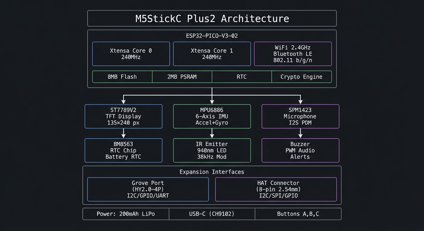
What Makes This Device Special
- Complete System: Unlike bare ESP32 modules, you get a working product—display, battery, sensors, case—ready to program
- Dual Expansion: Grove (I2C/UART) and HAT (SPI/GPIO) connectors support 100+ modules
- Portable: 54.2×25.5×13.7mm form factor fits in your pocket; wearable as a watch
- Production-Ready: Same hardware can go from prototype to deployed product
- Rich Ecosystem: Arduino, MicroPython, UIFlow (visual programming), and ESP-IDF support
What You’ll Learn Building With It
| Domain | Skills Gained |
|---|---|
| Embedded Programming | C/C++ on bare metal, memory management, interrupts, timers |
| Hardware Interfaces | SPI, I2C, UART, GPIO, ADC, PWM, I2S |
| Wireless Communication | WiFi networking, BLE beacons, MQTT/HTTP protocols |
| Display Graphics | Framebuffers, sprites, animations, UI design |
| Sensor Fusion | IMU data processing, gesture recognition, motion tracking |
| Power Management | Deep sleep, wake sources, battery optimization |
| IoT Architecture | Device-to-cloud, OTA updates, remote control |
Learning Outcomes Overview
This guide takes you from “I can flash a demo” to “I can design a production-grade IoT device.” You will learn how to:
- Build stable firmware that runs for days without crashing.
- Read sensors, filter their noise, and turn raw signals into meaningful data.
- Design responsive UIs on a tiny display without flicker or lag.
- Use WiFi/BLE safely and efficiently, including OTA updates.
- Optimize battery life using deep sleep and event-driven wakeups.
- Integrate external modules through Grove/HAT with correct bus timing.
The Big Picture: From Sensor to Cloud
Every project you build is a variation of this pipeline:
Sensors ─► Sampling ─► Filtering ─► Local UI ─► Radio ─► Cloud
   |           |           |           |         |        |
  IMU        timers      DSP         TFT      WiFi/BLE  MQTT/HTTP
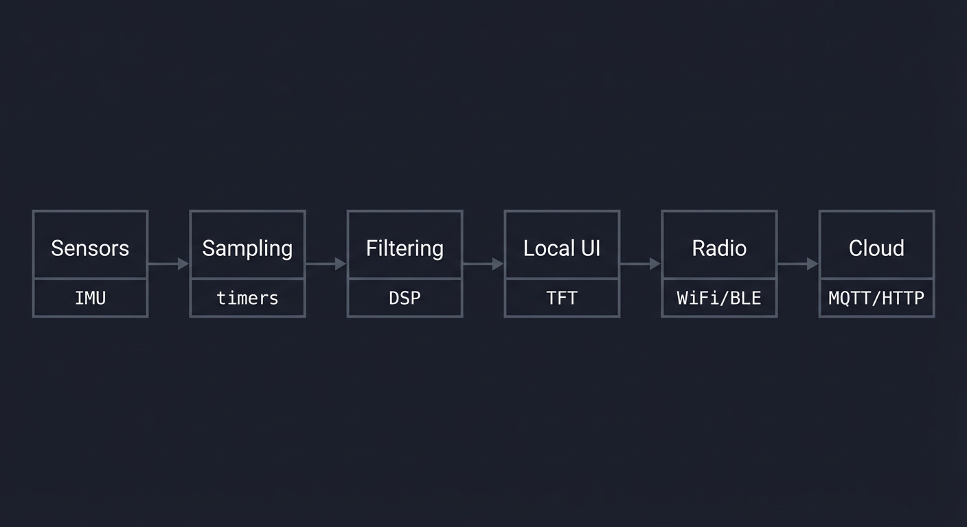
The StickC Plus2 is small, but the architecture is the same as modern wearables:
- Front end: sensors, buttons, IR, microphone
- Core: ESP32 dual-core + FreeRTOS
- Back end: WiFi/BLE + cloud endpoints
- Energy system: battery + sleep management
Once you understand this pipeline, you can design any IoT product.
Prerequisites & Background Knowledge
Essential Prerequisites (Must Have)
- Basic Arduino or C/C++ fundamentals (functions, loops, structs)
- Comfort with serial logs and flashing firmware
- Basic electronics: power, ground, pull-up resistors
Helpful But Not Required
- Familiarity with FreeRTOS tasks
- Simple networking concepts (IP, TCP/UDP)
- Basic signal processing (moving average, FFT)
Self-Assessment Questions
- Can you wire an I2C sensor correctly and scan its address?
- Can you debug a crash using serial logs?
- Can you read a datasheet table and extract pin requirements?
Development Environment Setup
- Arduino IDE or PlatformIO (recommended)
- M5StickC Plus2 board support package
- USB-C data cable
- Optional: logic analyzer for bus debugging
Time Investment
- Beginner path: 6–10 weeks
- Intermediate path: 4–6 weeks
- Advanced path: 3–5 weeks (if already familiar with ESP32)
How to Use This Guide
- Read the Core Question for each project and restate it.
- Implement minimal functionality first, then add polish.
- Validate with tests (sensor values, packet counts, frame rate).
- Measure power consumption at least once per project.
- Treat each project as a deployable product, not a throwaway demo.
Core Concept Analysis
Before building projects, you must internalize these foundational concepts.
0. Firmware Stack and Tooling
The StickC Plus2 firmware stack layers hardware, RTOS, and libraries:
Your App
  └─ M5Unified / TFT_eSPI / Arduino APIs
      └─ ESP32 Arduino Core
          └─ ESP-IDF (drivers, WiFi, BLE, NVS)
              └─ FreeRTOS (tasks, queues, timers)
                  └─ HAL + ROM (low-level peripherals)
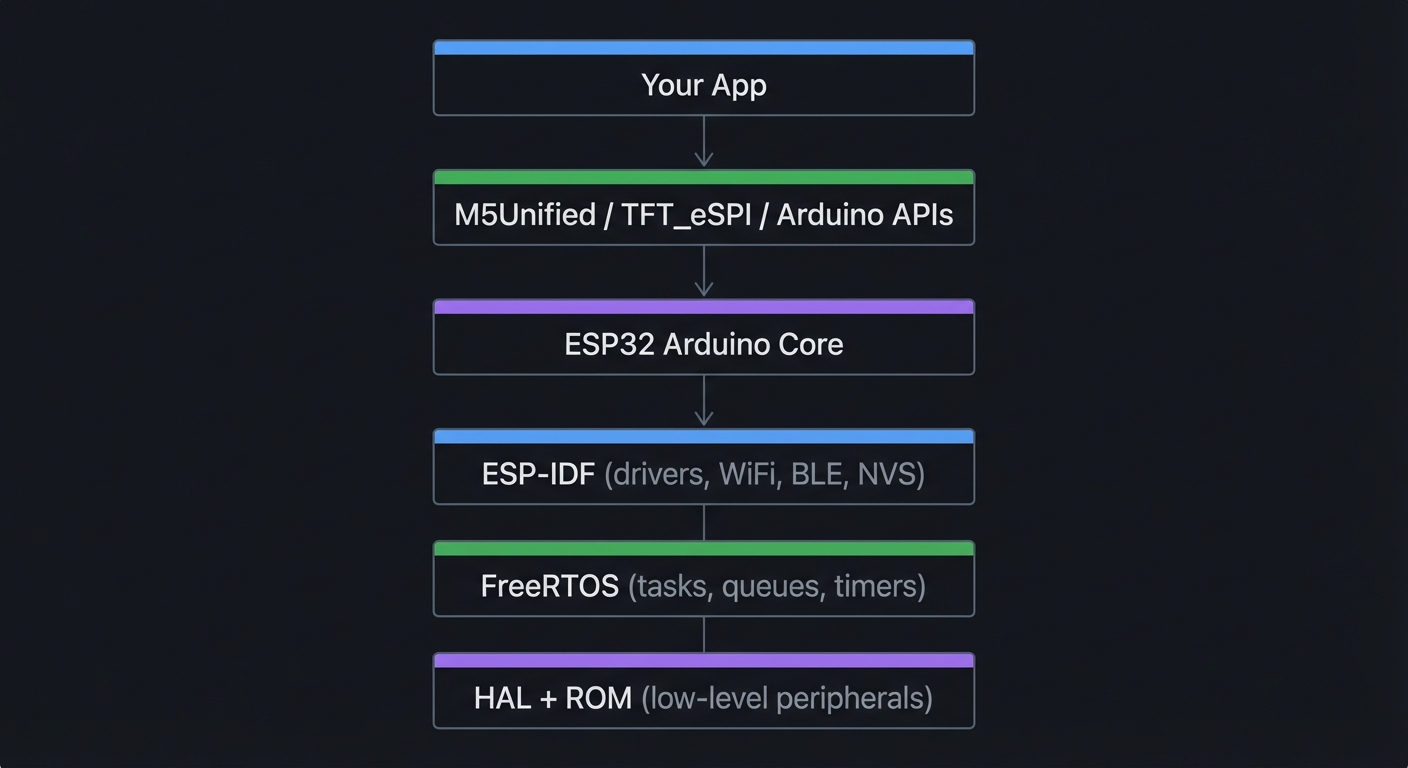
Key Insight: Bugs often hide across layers (e.g., a display glitch caused by SPI contention). Knowing the stack helps you debug faster.
1. The ESP32 Architecture
The ESP32-PICO-V3-02 in the StickC Plus2 is a System-in-Package (SiP):
┌─────────────────────────────────────────────────────────────────┐
│                    ESP32 Memory Architecture                     │
├─────────────────────────────────────────────────────────────────┤
│                                                                  │
│  Address Space (32-bit)                                          │
│  ├── 0x00000000 ─────────────────────────────────────────────   │
│  │                                                               │
│  ├── 0x3F400000  External Flash (8MB)                           │
│  │   ├── Bootloader                                              │
│  │   ├── Partition Table                                         │
│  │   ├── OTA App 0                                               │
│  │   ├── OTA App 1                                               │
│  │   ├── NVS (Non-Volatile Storage)                             │
│  │   └── SPIFFS/LittleFS                                         │
│  │                                                               │
│  ├── 0x3F800000  External PSRAM (2MB)                           │
│  │   └── Large buffers, sprites, audio                          │
│  │                                                               │
│  ├── 0x3FF00000  Peripheral Registers                           │
│  │   ├── GPIO, SPI, I2C, UART                                   │
│  │   ├── RMT (IR/LED control)                                   │
│  │   ├── I2S (Audio)                                            │
│  │   └── WiFi/BT MAC                                            │
│  │                                                               │
│  ├── 0x3FFB0000  Internal SRAM (520KB total)                    │
│  │   ├── SRAM0 (192KB) - Instruction cache                      │
│  │   ├── SRAM1 (128KB) - Data cache                             │
│  │   └── SRAM2 (200KB) - General purpose                        │
│  │                                                               │
│  └── 0x50000000  RTC Memory (8KB)                               │
│      └── Survives deep sleep!                                    │
│                                                                  │
└─────────────────────────────────────────────────────────────────┘
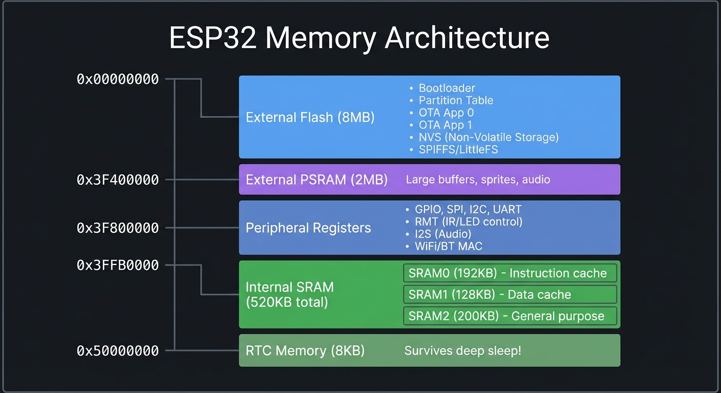
Key Insight: The ESP32 has limited internal RAM (~320KB usable), but 2MB of PSRAM for large buffers. Graphics and audio will use PSRAM.
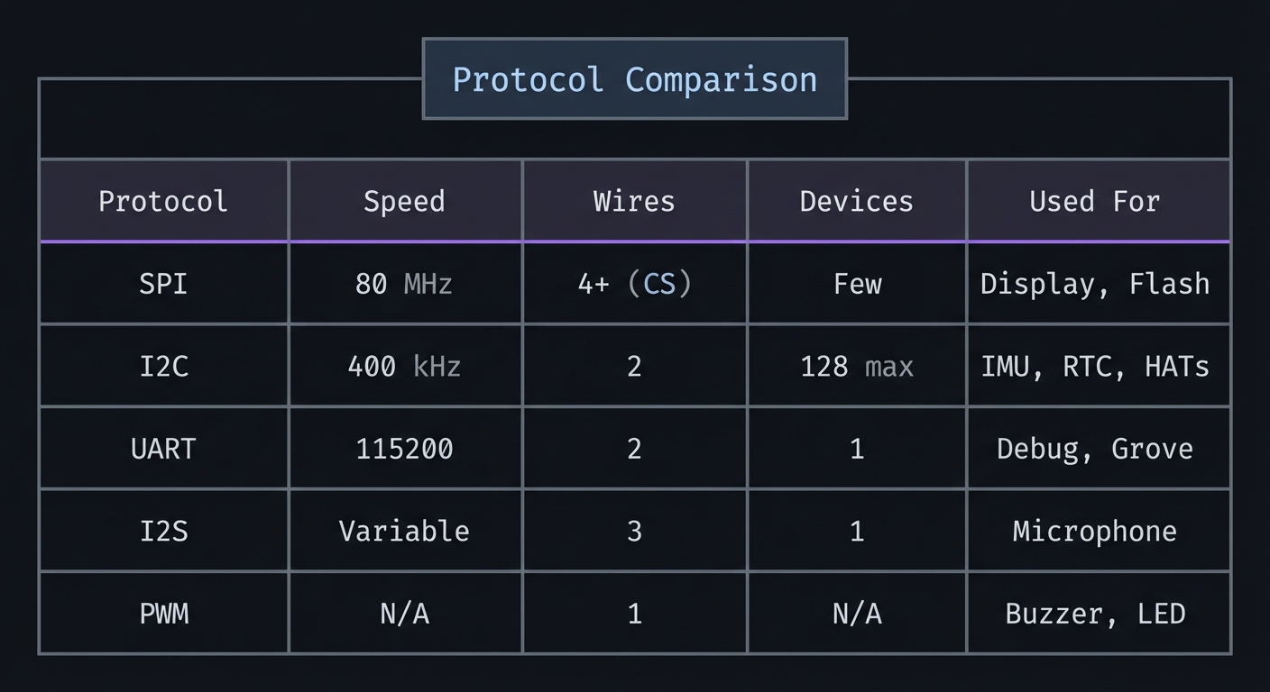
2. Communication Protocols
The StickC Plus2 uses multiple protocols to talk to its peripherals:
┌─────────────────────────────────────────────────────────────────┐
│                    Protocol Comparison                           │
├──────────┬───────────┬───────────┬───────────┬──────────────────┤
│ Protocol │  Speed    │  Wires    │  Devices  │  Used For        │
├──────────┼───────────┼───────────┼───────────┼──────────────────┤
│   SPI    │ 80 MHz    │  4+ (CS)  │  Few      │ Display, Flash   │
│   I2C    │ 400 kHz   │  2        │  128 max  │ IMU, RTC, HATs   │
│   UART   │ 115200    │  2        │  1        │ Debug, Grove     │
│   I2S    │ Variable  │  3        │  1        │ Microphone       │
│   PWM    │ N/A       │  1        │  N/A      │ Buzzer, LED      │
└──────────┴───────────┴───────────┴───────────┴──────────────────┘
SPI (Display - ST7789V2):
  ┌───────┐     MOSI    ┌─────────┐
  │       │────────────►│         │
  │ ESP32 │     SCLK    │ ST7789  │
  │       │────────────►│ Display │
  │       │     CS      │         │
  │       │────────────►│         │
  │       │     DC      │         │
  │       │────────────►│         │
  └───────┘             └─────────┘

I2C (IMU, RTC - Shared Bus):
  ┌───────┐     SDA     ┌─────────┐     ┌─────────┐
  │       │◄───────────►│ MPU6886 │     │ BM8563  │
  │ ESP32 │     SCL     │  (0x68) │     │  (0x51) │
  │       │────────────►│   IMU   │     │   RTC   │
  └───────┘             └────┬────┘     └────┬────┘
                             │               │
                         ◄───┴───────────────┘ (Same bus, different addresses)

3. Power States and Deep Sleep
Battery life is critical for portable devices. The ESP32 has multiple power modes:
┌─────────────────────────────────────────────────────────────────┐
│                    ESP32 Power States                            │
├─────────────────────────────────────────────────────────────────┤
│                                                                  │
│  Active Mode (WiFi TX): ~240mA                                   │
│  ┌─────────────────────────────────────────────────────────┐    │
│  │ ████████████████████████████████████████████████████████│    │
│  └─────────────────────────────────────────────────────────┘    │
│  Everything running, WiFi transmitting                           │
│                                                                  │
│  Modem Sleep: ~20mA                                              │
│  ┌───────────────────────────────┐                              │
│  │ ███████████████████████████████                              │
│  └───────────────────────────────┘                              │
│  CPU running, WiFi off                                           │
│                                                                  │
│  Light Sleep: ~0.8mA                                             │
│  ┌────────┐                                                      │
│  │ ████████                                                      │
│  └────────┘                                                      │
│  CPU paused, RAM retained, fast wake                             │
│                                                                  │
│  Deep Sleep: ~10µA                                               │
│  ┌──┐                                                            │
│  │ ██                                                            │
│  └──┘                                                            │
│  Only RTC running, 8KB RTC memory retained                       │
│  Wake sources: Timer, GPIO, Touch, ULP                           │
│                                                                  │
│  200mAh Battery Life Estimates:                                  │
│  ├── Active WiFi: ~50 minutes                                    │
│  ├── Active (no WiFi): ~5 hours                                  │
│  ├── Light Sleep: ~250 hours (10 days)                          │
│  └── Deep Sleep: ~2.3 years (!!)                                │
│                                                                  │
└─────────────────────────────────────────────────────────────────┘
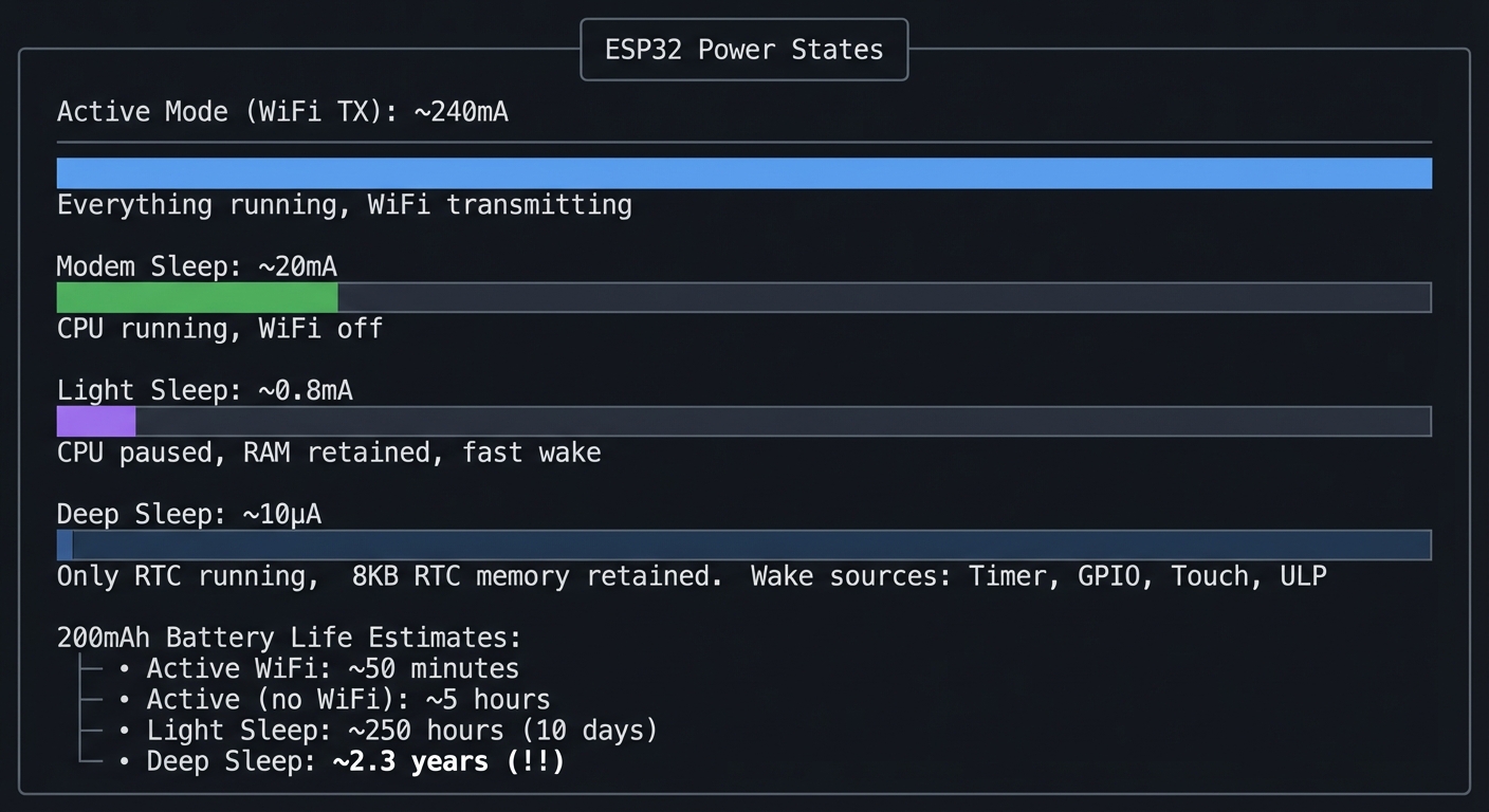
Key Insight: Real IoT devices spend 99%+ of time in deep sleep, waking only to sample sensors and transmit data.
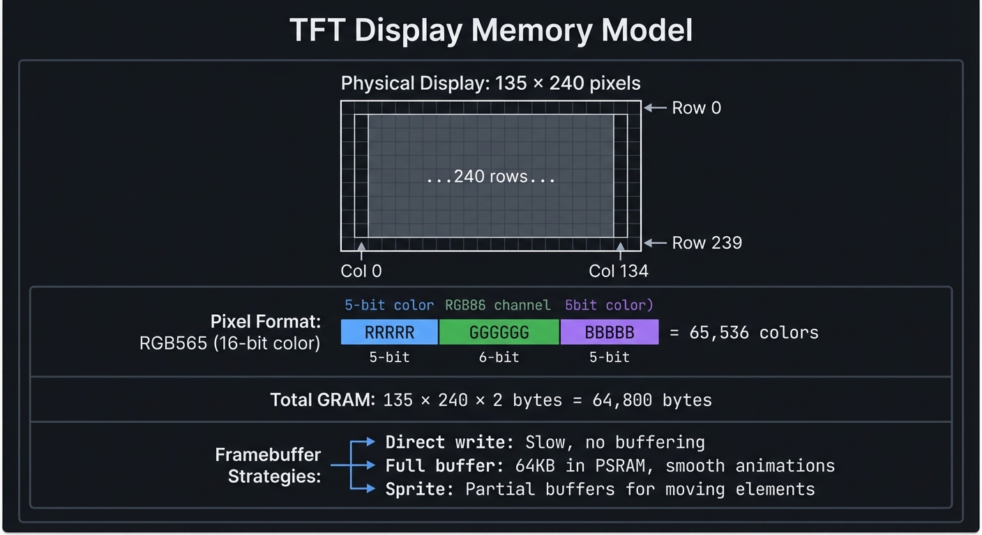
4. Display and Graphics
The ST7789V2 is a color TFT driven over SPI:
┌─────────────────────────────────────────────────────────────────┐
│                    TFT Display Memory Model                      │
├─────────────────────────────────────────────────────────────────┤
│                                                                  │
│  Physical Display: 135 × 240 pixels                              │
│  ┌─────────────────────────────────────────────┐                │
│  │░░░░░░░░░░░░░░░░░░░░░░░░░░░░░░░░░░░░░░░░░░░░░│ ← Row 0        │
│  │░░░░░░░░░░░░░░░░░░░░░░░░░░░░░░░░░░░░░░░░░░░░░│                │
│  │░░░░░░░░░░░░░░░░░░░░░░░░░░░░░░░░░░░░░░░░░░░░░│                │
│  │             ...240 rows...                  │                │
│  │░░░░░░░░░░░░░░░░░░░░░░░░░░░░░░░░░░░░░░░░░░░░░│ ← Row 239      │
│  └─────────────────────────────────────────────┘                │
│       ▲                                     ▲                   │
│       │                                     │                   │
│    Col 0                                 Col 134                │
│                                                                  │
│  Pixel Format: RGB565 (16-bit color)                            │
│  ┌──────────────────────────────────────────┐                   │
│  │ RRRRR │ GGGGGG │ BBBBB │  = 65,536 colors │                   │
│  │ 5-bit │ 6-bit  │ 5-bit │                  │                   │
│  └──────────────────────────────────────────┘                   │
│                                                                  │
│  Total GRAM: 135 × 240 × 2 bytes = 64,800 bytes                 │
│                                                                  │
│  Framebuffer Strategies:                                         │
│  ├── Direct write: Slow, no buffering                           │
│  ├── Full buffer: 64KB in PSRAM, smooth animations              │
│  └── Sprite: Partial buffers for moving elements                │
│                                                                  │
└─────────────────────────────────────────────────────────────────┘
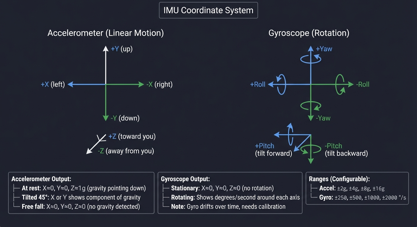
5. The IMU (Inertial Measurement Unit)
The MPU6886 provides 6 degrees of freedom:
┌─────────────────────────────────────────────────────────────────┐
│                    IMU Coordinate System                         │
├─────────────────────────────────────────────────────────────────┤
│                                                                  │
│         Accelerometer                    Gyroscope               │
│         (Linear Motion)                  (Rotation)              │
│                                                                  │
│              +Y (up)                       +Yaw                  │
│               ▲                             ⟳                    │
│               │                             │                    │
│               │                             │                    │
│    +X ◄───────┼─────────► -X     +Roll ◄────┼────► -Roll         │
│   (left)      │        (right)              │                    │
│               │                             │                    │
│               ▼                             ▼                    │
│              -Y (down)                    -Yaw                   │
│                                                                  │
│           +Z (toward you)              +Pitch (tilt forward)     │
│           -Z (away from you)           -Pitch (tilt backward)    │
│                                                                  │
│  Accelerometer Output:                                           │
│  ├── At rest: X≈0, Y≈0, Z≈1g (gravity pointing down)           │
│  ├── Tilted 45°: X or Y shows component of gravity              │
│  └── Free fall: X≈0, Y≈0, Z≈0 (no gravity detected)            │
│                                                                  │
│  Gyroscope Output:                                               │
│  ├── Stationary: X≈0, Y≈0, Z≈0 (no rotation)                   │
│  ├── Rotating: Shows degrees/second around each axis            │
│  └── Note: Gyro drifts over time, needs calibration             │
│                                                                  │
│  Ranges (Configurable):                                          │
│  ├── Accel: ±2g, ±4g, ±8g, ±16g                                 │
│  └── Gyro: ±250, ±500, ±1000, ±2000 °/s                        │
│                                                                  │
└─────────────────────────────────────────────────────────────────┘
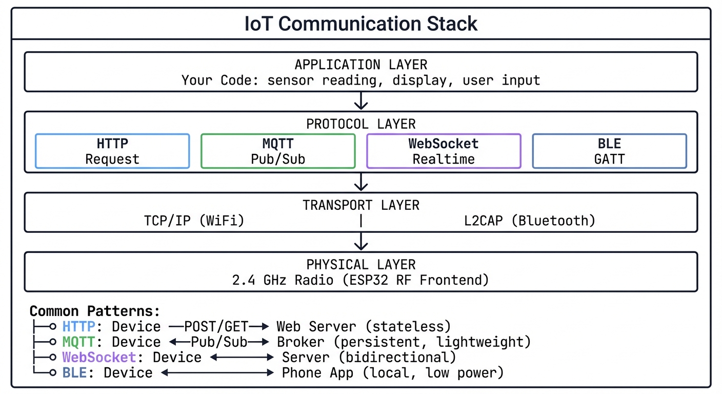
6. Wireless Communication Stack
┌─────────────────────────────────────────────────────────────────┐
│                    IoT Communication Stack                       │
├─────────────────────────────────────────────────────────────────┤
│                                                                  │
│  ┌─────────────────────────────────────────────────────────┐    │
│  │                    APPLICATION LAYER                     │    │
│  │   Your Code: sensor reading, display, user input        │    │
│  └─────────────────────────────────────────────────────────┘    │
│                            │                                     │
│                            ▼                                     │
│  ┌─────────────────────────────────────────────────────────┐    │
│  │                    PROTOCOL LAYER                        │    │
│  │   ┌─────────┐  ┌─────────┐  ┌─────────┐  ┌─────────┐   │    │
│  │   │  HTTP   │  │  MQTT   │  │ WebSocket│  │   BLE   │   │    │
│  │   │ Request │  │Pub/Sub  │  │Realtime │  │ GATT    │   │    │
│  │   └─────────┘  └─────────┘  └─────────┘  └─────────┘   │    │
│  └─────────────────────────────────────────────────────────┘    │
│                            │                                     │
│                            ▼                                     │
│  ┌─────────────────────────────────────────────────────────┐    │
│  │                    TRANSPORT LAYER                       │    │
│  │          TCP/IP (WiFi)    │    L2CAP (Bluetooth)        │    │
│  └─────────────────────────────────────────────────────────┘    │
│                            │                                     │
│                            ▼                                     │
│  ┌─────────────────────────────────────────────────────────┐    │
│  │                    PHYSICAL LAYER                        │    │
│  │          2.4 GHz Radio (ESP32 RF Frontend)              │    │
│  └─────────────────────────────────────────────────────────┘    │
│                                                                  │
│  Common Patterns:                                                │
│  ├── HTTP: Device ──POST/GET──► Web Server (stateless)          │
│  ├── MQTT: Device ◄──Pub/Sub──► Broker (persistent, lightweight)│
│  ├── WebSocket: Device ◄──────► Server (bidirectional)          │
│  └── BLE: Device ◄──────────► Phone App (local, low power)      │
│                                                                  │
└─────────────────────────────────────────────────────────────────┘
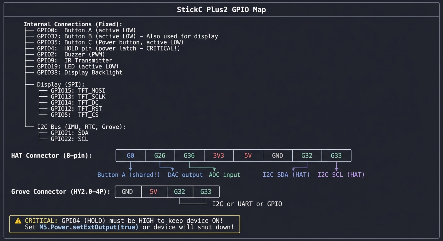
7. GPIO and Pin Functions
The StickC Plus2 exposes limited but versatile pins:
┌─────────────────────────────────────────────────────────────────┐
│                    StickC Plus2 GPIO Map                         │
├─────────────────────────────────────────────────────────────────┤
│                                                                  │
│  Internal Connections (Fixed):                                   │
│  ├── GPIO0:  Button A (active LOW)                              │
│  ├── GPIO37: Button B (active LOW) - Also used for display      │
│  ├── GPIO35: Button C (Power button, active LOW)                │
│  ├── GPIO4:  HOLD pin (power latch - CRITICAL!)                 │
│  ├── GPIO2:  Buzzer (PWM)                                       │
│  ├── GPIO9:  IR Transmitter                                     │
│  ├── GPIO19: LED (active LOW)                                   │
│  ├── GPIO38: Display Backlight                                  │
│  │                                                               │
│  │   Display (SPI):                                              │
│  ├── GPIO15: TFT_MOSI                                           │
│  ├── GPIO13: TFT_SCLK                                           │
│  ├── GPIO14: TFT_DC                                             │
│  ├── GPIO12: TFT_RST                                            │
│  ├── GPIO5:  TFT_CS                                             │
│  │                                                               │
│  │   I2C Bus (IMU, RTC, Grove):                                  │
│  ├── GPIO21: SDA                                                │
│  └── GPIO22: SCL                                                │
│                                                                  │
│  HAT Connector (8-pin):                                          │
│  ┌────┬────┬────┬────┬────┬────┬────┬────┐                     │
│  │ G0 │G26 │G36 │3V3 │5V  │GND │G32 │G33 │                     │
│  └────┴────┴────┴────┴────┴────┴────┴────┘                     │
│    │    │    │                    │    │                        │
│    │    │    └── ADC input        │    └── I2C SCL (HAT)        │
│    │    └── DAC output            └── I2C SDA (HAT)             │
│    └── Button A (shared!)                                        │
│                                                                  │
│  Grove Connector (HY2.0-4P):                                     │
│  ┌────┬────┬────┬────┐                                          │
│  │GND │5V  │G32 │G33 │                                          │
│  └────┴────┴────┴────┘                                          │
│             │    │                                               │
│             └────┴── I2C or UART or GPIO                        │
│                                                                  │
│  ⚠️  CRITICAL: GPIO4 (HOLD) must be HIGH to keep device ON!     │
│      Set M5.Power.setExtOutput(true) or device will shut down!  │
│                                                                  │
└─────────────────────────────────────────────────────────────────┘
8. Real-Time Tasking and Timing Budget
Tiny devices still have a timing budget. If your render loop is too slow, sensors lag; if WiFi blocks, UI freezes.
16ms frame budget @ 60 FPS
├── 4ms sensor read + filter
├── 6ms UI render
├── 2ms radio tasks
└── 4ms margin / interrupts
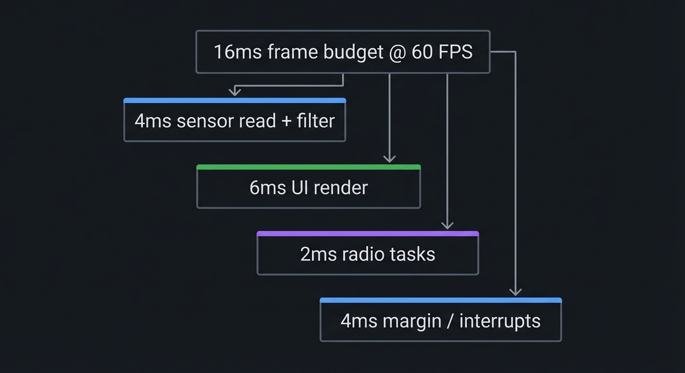
Key Insight: Use non-blocking operations and short critical sections. Long WiFi calls should run in a separate task.
Concept Summary Table
| Concept Cluster | What You Need to Internalize |
|---|---|
| ESP32 Architecture | Dual-core processor with limited RAM (~320KB), 8MB flash for code/data, 2MB PSRAM for buffers. Memory-mapped peripherals. |
| Communication Protocols | SPI for high-speed (display), I2C for sensors (shared bus, addresses), UART for serial, I2S for audio. Each has timing/wiring requirements. |
| Power Management | Deep sleep draws 10µA vs 240mA active. Battery life depends on duty cycle. RTC memory survives sleep. Wake sources: timer, GPIO, touch. |
| Display Graphics | RGB565 format (16-bit color), framebuffers eliminate flicker, sprites for animation. PSRAM holds large buffers. |
| IMU Physics | Accelerometer measures linear motion + gravity. Gyroscope measures rotation. Sensor fusion combines both for orientation. Drift requires calibration. |
| Wireless Protocols | WiFi for internet (high power), BLE for local (low power). MQTT for IoT pub/sub, HTTP for request/response, BLE GATT for services/characteristics. |
| GPIO & Peripherals | Limited exposed pins. Internal connections fixed. HOLD pin (GPIO4) critical for power. Button states are active-LOW. |
| Firmware Stack | Arduino runs on ESP-IDF/FreeRTOS. Driver conflicts and blocking calls are common bugs. |
| Real-Time Timing | UI + sensor + radio must fit within frame budget. Use tasks and non-blocking APIs. |
Success Metrics (What “Mastery” Looks Like)
You can consider this track successful when you can:
- Explain how each peripheral communicates and debug it with logs or bus scans.
- Build a UI that stays responsive while networking in the background.
- Deploy OTA updates safely without bricking the device.
- Measure and optimize power consumption for a real battery target.
- Integrate at least one external HAT/Grove module from scratch.
Deep Dive Reading by Concept
This section maps each concept from above to specific book chapters for deeper understanding.
Embedded Systems Fundamentals
| Concept | Book & Chapter |
|---|---|
| Microcontroller Architecture | Making Embedded Systems, 2nd Edition by Elecia White — Ch. 2: “Creating a System Architecture” |
| Memory-Mapped I/O | Computer Systems: A Programmer’s Perspective by Bryant & O’Hallaron — Ch. 6: “The Memory Hierarchy” |
| Interrupt Handling | Making Embedded Systems by Elecia White — Ch. 5: “Interrupts” |
| RTOS Scheduling | Making Embedded Systems by Elecia White — Ch. 6: “Scheduling” |
| Power Optimization | Making Embedded Systems by Elecia White — Ch. 10: “Reducing Power Consumption” |
Communication Protocols
| Concept | Book & Chapter |
|---|---|
| SPI Protocol | The Book of I2C by Randall Hyde — Ch. 2: “SPI vs I2C Comparison” |
| I2C Protocol | The Book of I2C by Randall Hyde — Ch. 3-5: “I2C Fundamentals” |
| UART/Serial | Making Embedded Systems by Elecia White — Ch. 8: “Serial Drivers” |
Wireless & Networking
| Concept | Book & Chapter |
|---|---|
| TCP/IP Fundamentals | Computer Networks, 5th Edition by Tanenbaum — Ch. 5-6: “Transport Layer” |
| MQTT Protocol | Designing Data-Intensive Applications by Kleppmann — Ch. 4: “Encoding and Evolution” (messaging patterns) |
| Bluetooth Low Energy | Getting Started with Bluetooth Low Energy by Townsend (O’Reilly) — All chapters |
Power & Hardware
| Concept | Book & Chapter |
|---|---|
| Low-Power Design | Making Embedded Systems by Elecia White — Ch. 10: “Reducing Power Consumption” |
| Battery Management | AVR Workshop by John Boxall — Ch. 8: “Power Management” |
| Sensor Interfacing | Arduino Workshop, 2nd Edition by John Boxall — Ch. 9-12: “Sensors” |
Essential Reading Order
For maximum comprehension, read in this order:
- Foundation (Week 1-2):
- Making Embedded Systems Ch. 1-2 (architecture)
- Arduino Workshop Ch. 1-4 (getting started)
- Communication (Week 3):
- The Book of I2C Ch. 1-5 (protocols)
- Making Embedded Systems Ch. 8 (serial drivers)
- Advanced Topics (Week 4+):
- Making Embedded Systems Ch. 10 (power)
- Computer Networks Ch. 5 (TCP/IP for WiFi understanding)
Project List
The following 12 projects take you from beginner to advanced, covering all major capabilities of the M5Stack StickC Plus2.
Project 1: Digital Instrument Cluster (Display & Graphics Mastery)
- File: LEARN_M5STACK_STICKC_PLUS2_DEEP_DIVE.md
- Main Programming Language: C++ (Arduino)
- Alternative Programming Languages: MicroPython, Rust (esp-rs)
- Coolness Level: Level 3: Genuinely Clever
- Business Potential: 2. The “Micro-SaaS / Pro Tool”
- Difficulty: Level 1: Beginner
- Knowledge Area: Embedded Graphics, SPI Protocol, Framebuffers
- Software or Tool: TFT_eSPI library, ST7789 display driver
- Main Book: “Making Embedded Systems, 2nd Edition” by Elecia White
What you’ll build: A real-time dashboard showing animated gauges, text, and graphics—demonstrating framebuffer techniques that eliminate flicker and enable smooth animations on the 135×240 TFT display.
Why it teaches display programming: Before you can build any visual IoT project, you must master the display. This project forces you to understand RGB565 color encoding, SPI communication timing, sprite-based rendering, and how to achieve smooth animation with limited memory.
Core challenges you’ll face:
- Understanding the ST7789 command set → maps to how display controllers work
- Eliminating screen flicker → maps to framebuffer and double-buffering concepts
- Managing memory for sprites → maps to PSRAM allocation and memory constraints
- Achieving smooth animation → maps to refresh rates and drawing optimization
Key Concepts:
- SPI Communication: Making Embedded Systems Ch. 8 - Elecia White
- Framebuffer Rendering: TFT_eSPI library documentation - Bodmer
- Color Encoding (RGB565): Computer Graphics from Scratch Ch. 2 - Gabriel Gambetta
- Memory Management: ESP32 Technical Reference Manual - Espressif
Difficulty: Beginner Time estimate: Weekend Prerequisites: Basic Arduino knowledge (setup/loop), understanding of functions and variables, ability to install libraries in Arduino IDE
Real World Outcome
You’ll have a mini instrument panel that displays multiple animated gauges, updating in real-time with no visible flicker. When you run it:
- The display shows two analog-style gauges (speedometer and tachometer style)
- Needle positions animate smoothly as values change
- A digital readout shows precise values
- Frame rate counter proves you’re hitting 30+ FPS
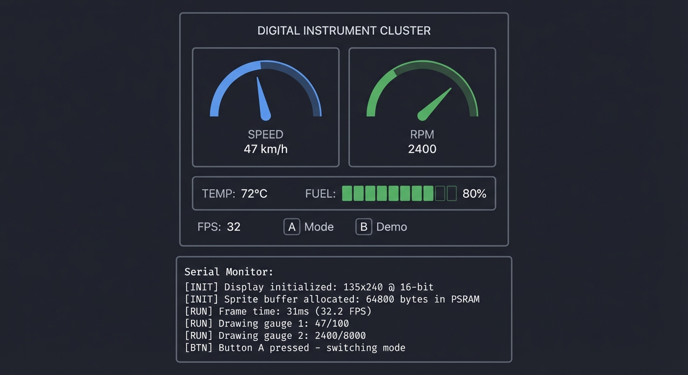
Example Output:
┌──────────────────────────────────────────────┐
│           DIGITAL INSTRUMENT CLUSTER         │
├──────────────────────────────────────────────┤
│  ┌─────────────┐    ┌─────────────┐          │
│  │     ◠◠◠     │    │     ◠◠◠     │          │
│  │   ╱     ╲   │    │   ╱     ╲   │          │
│  │  │   ╲    │ │    │  │    ╱  │  │          │
│  │   ╲  ▼  ╱   │    │   ╲  ▼  ╱   │          │
│  │     ◡◡◡     │    │     ◡◡◡     │          │
│  │   SPEED     │    │    RPM      │          │
│  │    47 km/h  │    │   2400      │          │
│  └─────────────┘    └─────────────┘          │
│                                              │
│  TEMP: 72°C    FUEL: ████████░░ 80%          │
│                                              │
│  FPS: 32       [A] Mode  [B] Demo            │
└──────────────────────────────────────────────┘

Serial Monitor:
[INIT] Display initialized: 135x240 @ 16-bit
[INIT] Sprite buffer allocated: 64800 bytes in PSRAM
[RUN] Frame time: 31ms (32.2 FPS)
[RUN] Drawing gauge 1: 47/100
[RUN] Drawing gauge 2: 2400/8000
[BTN] Button A pressed - switching mode
The Core Question You’re Answering
“How do professional embedded devices display smooth, flicker-free animations on tiny screens with limited memory?”
Before you write any code, sit with this question. The StickC Plus2 has only ~320KB of usable RAM, but the display needs 64KB just for one frame. How do commercial products like smartwatches achieve buttery-smooth graphics? The answer lies in understanding framebuffers, sprites, and the art of drawing only what changes.
Concepts You Must Understand First
Stop and research these before coding:
- SPI (Serial Peripheral Interface)
- What are the four main SPI signals (MOSI, MISO, SCLK, CS)?
- Why does SPI use a clock signal when UART doesn’t?
- What determines SPI transfer speed?
- Book Reference: “The Book of I2C” Ch. 2 - Randall Hyde
- Framebuffers and Double Buffering
- What is a framebuffer and where does it live in memory?
- Why does drawing directly to the screen cause flicker?
- How does double-buffering solve this?
- Book Reference: “Computer Graphics from Scratch” Ch. 1 - Gabriel Gambetta
- RGB Color Models
- Why does RGB565 use 5-6-5 bits instead of 8-8-8?
- How do you convert RGB888 to RGB565?
- What colors are lost in this conversion?
- Book Reference: “Computer Graphics from Scratch” Ch. 2 - Gabriel Gambetta
Questions to Guide Your Design
Before implementing, think through these:
- Memory Budget
- How many bytes does one full-screen framebuffer require?
- Will this fit in internal RAM or must you use PSRAM?
- Can you use a smaller sprite for just the moving parts?
- Drawing Strategy
- Should you redraw the entire screen every frame?
- Can you draw static elements once and only update moving parts?
- How will you handle overlapping elements?
- Animation Approach
- How will you calculate needle position from a value?
- What trigonometry do you need for circular gauges?
- How will you smooth motion to avoid jerky updates?
Thinking Exercise
Trace the Pixel Path
Before coding, trace how a single pixel gets from your code to the display:
sprite.drawPixel(67, 120, TFT_RED);  // Center of 135-wide screen
sprite.pushSprite(0, 0);              // Send to display
Questions while tracing:
- Where is the pixel value (TFT_RED = 0xF800) stored before pushSprite?
- How many bytes are transferred over SPI when pushSprite runs?
- What commands does the ESP32 send to tell the display WHERE to put these bytes?
- At 80MHz SPI clock, how long does transferring one full frame take?
Calculate: 135 × 240 × 2 bytes = 64,800 bytes. At 80 MHz, with 8 bits per clock: 64,800 × 8 ÷ 80,000,000 = ~6.5ms per frame. You could theoretically hit 150 FPS just from transfer time!
The Interview Questions They’ll Ask
Prepare to answer these:
- “Explain the difference between SPI and I2C. When would you use each?”
- “What is double buffering and why is it important for graphics?”
- “How does the ESP32 manage memory between internal RAM and PSRAM?”
- “Describe RGB565 color format. Why is it used in embedded displays?”
- “How would you optimize drawing performance on a memory-constrained device?”
Hints in Layers
Hint 1: Getting Started Install the M5StickCPlus2 library through Arduino IDE Library Manager. The library includes display drivers. Start with the “Display” example.
Hint 2: Creating Sprites Look at TFT_eSPI’s sprite examples. A sprite is just an off-screen canvas. Create one the size of your gauge, draw there, then push to screen.
Hint 3: Drawing Gauge Needles For a needle pointing at angle θ from center (cx, cy) with length r:
- endpoint_x = cx + r * cos(θ)
- endpoint_y = cy + r * sin(θ) Convert your 0-100 value to radians: θ = map(value, 0, 100, -135°, 135°) × π/180
Hint 4: Optimizing Refresh
Use sprite.createSprite(width, height) in PSRAM. Draw background once to a static sprite. Each frame: copy background to working sprite, draw needles, push to display.
Common Pitfalls & Debugging
Problem: “Screen flickers during animation”
- Why: Full-screen redraw without buffering
- Fix: Use sprites or partial buffers in PSRAM and only blit changed regions
- Quick test: Track FPS before and after buffering
Problem: “Graphics corruption after a few seconds”
- Why: Buffer overflow or PSRAM not enabled
- Fix: Ensure PSRAM enabled and buffers sized for 135x240 RGB565
- Quick test: Allocate a 64KB buffer and render a solid color
Definition of Done
- UI renders at 30+ FPS without flicker
- Uses sprites or partial buffers in PSRAM
- SPI display init is reliable across reboots
- Frame time logged and stays under budget
Books That Will Help
| Topic | Book | Chapter |
|---|---|---|
| Display drivers | “Making Embedded Systems” by Elecia White | Ch. 8 |
| Graphics fundamentals | “Computer Graphics from Scratch” by Gambetta | Ch. 1-2 |
| SPI protocol | “The Book of I2C” by Randall Hyde | Ch. 2 |
| ESP32 memory | ESP32 Technical Reference Manual | Ch. 4 |
Implementation Hints
The key insight for this project is understanding the sprite workflow:
- Create sprites in setup(): Allocate memory once for your drawing canvases
- Draw static elements once: Background, gauge faces, labels
- In loop(), only redraw what changes: Clear sprite, copy background, draw needles, push
The TFT_eSPI library provides the TFT_eSprite class. Study how createSprite(), fillSprite(), drawLine(), and pushSprite() work together.
For smooth needle motion, don’t jump instantly to new values. Implement easing:
current = current + (target - current) * 0.1; // Smooth approach
Learning milestones:
- Display shows static text and shapes → You understand basic TFT commands
- Sprite-based drawing eliminates flicker → You understand buffering
- Gauges animate smoothly at 30+ FPS → You’ve mastered the graphics pipeline
Project 2: Environmental Monitor with Cloud Dashboard (WiFi & MQTT)
- File: LEARN_M5STACK_STICKC_PLUS2_DEEP_DIVE.md
- Main Programming Language: C++ (Arduino)
- Alternative Programming Languages: MicroPython, ESP-IDF (C)
- Coolness Level: Level 3: Genuinely Clever
- Business Potential: 3. The “Service & Support” Model
- Difficulty: Level 2: Intermediate
- Knowledge Area: WiFi Networking, MQTT Protocol, IoT Architecture
- Software or Tool: PubSubClient (MQTT), ENV Hat III, Home Assistant
- Main Book: “Designing Data-Intensive Applications” by Martin Kleppmann
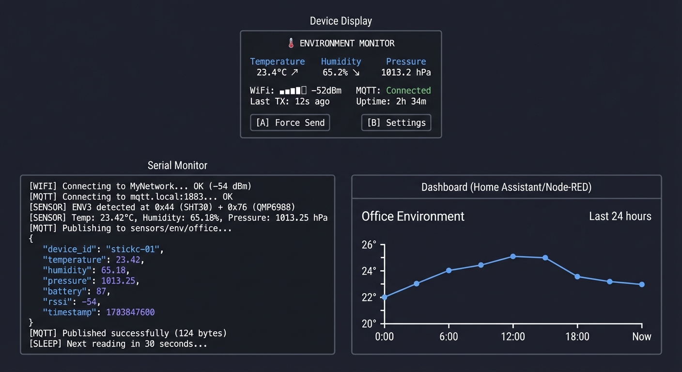
What you’ll build: A wireless environmental sensor station that reads temperature, humidity, and pressure from an ENV Hat, publishes data to an MQTT broker, and displays current readings on the device while a web dashboard shows historical trends.
Why it teaches IoT architecture: This is THE fundamental IoT pattern: sense → process → transmit → visualize. You’ll understand the complete data pipeline from physical sensor to cloud storage, learning MQTT’s publish/subscribe model that powers billions of IoT devices.
Core challenges you’ll face:
- Connecting to WiFi reliably → maps to network stack initialization and error handling
- Understanding MQTT pub/sub → maps to message broker architecture
- Formatting sensor data for transmission → maps to JSON serialization and data schemas
- Handling network failures gracefully → maps to resilient IoT design patterns
Key Concepts:
- MQTT Protocol: Designing Data-Intensive Applications Ch. 4 - Martin Kleppmann
- WiFi Connection Management: ESP32 WiFi documentation - Espressif
- JSON Serialization: ArduinoJson library documentation - Benoît Blanchon
- I2C Sensor Reading: The Book of I2C Ch. 4 - Randall Hyde
Difficulty: Intermediate Time estimate: 1 week Prerequisites: Project 1 completed, basic understanding of WiFi/internet concepts, comfort with JSON format
Real World Outcome
You’ll have a complete IoT environmental monitoring system:
- The device wakes up, connects to WiFi, reads sensors
- Current readings display on the screen with trend indicators
- Data publishes to MQTT broker every 30 seconds
- A dashboard (Home Assistant, Node-RED, or custom) shows graphs
Example Output:
Device Display:
┌──────────────────────────────────────────────┐
│        🌡️ ENVIRONMENT MONITOR               │
├──────────────────────────────────────────────┤
│                                              │
│   Temperature    Humidity     Pressure       │
│    23.4°C ↗     65.2% ↘     1013.2 hPa      │
│                                              │
│   WiFi: ████░ -52dBm    MQTT: Connected     │
│   Last TX: 12s ago      Uptime: 2h 34m      │
│                                              │
│   [A] Force Send    [B] Settings            │
└──────────────────────────────────────────────┘

Serial Monitor:
[WIFI] Connecting to MyNetwork... OK (-54 dBm)
[MQTT] Connecting to mqtt.local:1883... OK
[SENSOR] ENV3 detected at 0x44 (SHT30) + 0x76 (QMP6988)
[SENSOR] Temp: 23.42°C, Humidity: 65.18%, Pressure: 1013.25 hPa
[MQTT] Publishing to sensors/env/office...
{
  "device_id": "stickc-01",
  "temperature": 23.42,
  "humidity": 65.18,
  "pressure": 1013.25,
  "battery": 87,
  "rssi": -54,
  "timestamp": 1703847600
}
[MQTT] Published successfully (124 bytes)
[SLEEP] Next reading in 30 seconds...

Dashboard (Home Assistant/Node-RED):
┌─────────────────────────────────────────────────────────────┐
│ Office Environment                           Last 24 hours  │
├─────────────────────────────────────────────────────────────┤
│ Temperature                                                  │
│ 26°┤                    ╭───╮                               │
│ 24°┤         ╭─────────╯   ╰───────────╮                   │
│ 22°┤────────╯                           ╰───────           │
│ 20°┼──────────────────────────────────────────────────────  │
│    └──────────────────────────────────────────────────────  │
│      0:00    6:00    12:00    18:00    Now                  │
└─────────────────────────────────────────────────────────────┘
The Core Question You’re Answering
“How do IoT devices reliably send sensor data to the cloud while handling real-world network failures?”
Before you write any code, sit with this question. Your home WiFi drops occasionally. Your MQTT broker might restart. Power might fluctuate. A real IoT device must handle all these gracefully—buffering data, reconnecting automatically, and never losing measurements. This is what separates a hobby project from a production device.
Concepts You Must Understand First
Stop and research these before coding:
- MQTT Protocol Fundamentals
- What is a broker and why doesn’t MQTT use direct client-to-client?
- What are topics and how does the hierarchy work (e.g., home/office/temperature)?
- What are QoS levels 0, 1, 2 and when would you use each?
- What is a “retained” message and why is it useful?
- Book Reference: “Designing Data-Intensive Applications” Ch. 4 - Kleppmann
- WiFi Connection Lifecycle
- What happens between calling WiFi.begin() and being connected?
- What is DHCP and how does your device get an IP address?
- What is RSSI and what values indicate good/poor signal?
- Book Reference: “Computer Networks” Ch. 6 - Tanenbaum
- I2C Multi-Sensor Communication
- How does I2C addressing work when multiple devices share the bus?
- How do you discover devices on the I2C bus (scanning)?
- Book Reference: “The Book of I2C” Ch. 4 - Randall Hyde
Questions to Guide Your Design
Before implementing, think through these:
- Reliability
- What should happen if WiFi connection fails?
- Should you buffer readings locally if MQTT is unreachable?
- How many readings will you store, and where (RAM vs Flash)?
- Data Format
- What fields does your JSON payload need?
- How will you include a timestamp if the device has no internet time?
- Should you use NTP to sync time?
- Power Strategy
- Should the device stay on continuously or use deep sleep?
- If deep sleep, how do you maintain MQTT connection state?
- What’s the tradeoff between update frequency and battery life?
Thinking Exercise
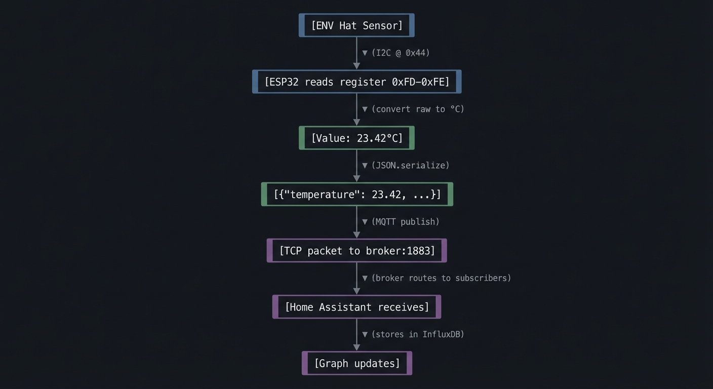
Map the Data Flow
Before coding, diagram the complete path of a temperature reading:
[ENV Hat Sensor]
       │
       ▼ (I2C @ 0x44)
[ESP32 reads register 0xFD-0xFE]
       │
       ▼ (convert raw to °C)
[Value: 23.42°C]
       │
       ▼ (JSON.serialize)
[{"temperature": 23.42, ...}]
       │
       ▼ (MQTT publish)
[TCP packet to broker:1883]
       │
       ▼ (broker routes to subscribers)
[Home Assistant receives]
       │
       ▼ (stores in InfluxDB)
[Graph updates]
Questions while mapping:
- How many bytes is one JSON payload?
- At 30-second intervals, how much data per day?
- If the broker is 100ms away, how much latency is acceptable?
- What happens to subscribers if they’re offline when you publish?
The Interview Questions They’ll Ask
Prepare to answer these:
- “Compare MQTT with HTTP for IoT applications. When would you choose each?”
- “What is the publish/subscribe pattern and why is it suited for IoT?”
- “How would you handle a scenario where network is unavailable for hours?”
- “Explain MQTT QoS levels and their delivery guarantees.”
- “How would you secure MQTT communication for production IoT devices?”
Hints in Layers
Hint 1: Start Simple
Get WiFi connected first. Use WiFi.status() == WL_CONNECTED to verify. Print your IP address to serial.
Hint 2: Add MQTT
Install PubSubClient library. Connect to a free broker like test.mosquitto.org for testing. Subscribe to your own topic to verify messages arrive.
Hint 3: Add Sensors The ENV Hat III uses SHT30 (temp/humidity at 0x44) and QMP6988 (pressure at 0x76). Use Wire.h to scan for devices first.
Hint 4: Error Handling Wrap network operations in retry loops with exponential backoff:
int retries = 0;
while (!mqtt.connect() && retries < 5) {
    delay(1000 * (1 << retries));  // 1s, 2s, 4s, 8s, 16s
    retries++;
}
Common Pitfalls & Debugging
Problem: “MQTT publishes but dashboard is empty”
- Why: Wrong topic or broker auth
- Fix: Verify topic strings and credentials; test with a known client
- Quick test: Use mosquitto_sub to confirm messages arrive
Problem: “Device stops updating after WiFi drop”
- Why: No reconnect loop or stale socket
- Fix: Implement reconnect + re-subscribe logic
- Quick test: Disable WiFi router for 30s and verify recovery
Definition of Done
- Publishes sensor data to MQTT/HTTP reliably
- Dashboard updates in near real time
- Reconnect logic survives WiFi outages
- Credentials stored securely in NVS
Books That Will Help
| Topic | Book | Chapter |
|---|---|---|
| MQTT architecture | “Designing Data-Intensive Applications” by Kleppmann | Ch. 4 |
| Network reliability | “Release It!” by Nygard | Ch. 4-5 |
| I2C sensors | “The Book of I2C” by Randall Hyde | Ch. 4 |
| JSON in embedded | ArduinoJson documentation | Tutorial section |
Implementation Hints
The key architectural pattern is the state machine for connection management:
States: DISCONNECTED → CONNECTING_WIFI → CONNECTING_MQTT → CONNECTED → PUBLISHING
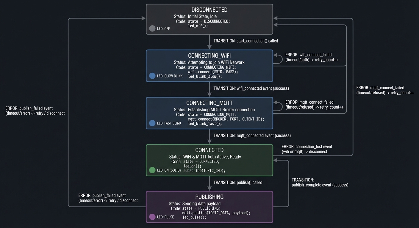
Each state handles its own errors and knows how to transition. Don’t try to do everything in one big if-else chain.
For the ENV Hat III, M5Stack provides the M5Unit-ENV library. Study how it abstracts the I2C communication for multiple sensors.
Consider using NTP to sync time so your timestamps are meaningful. The configTime() function in ESP32 makes this easy.
Learning milestones:
- Device connects to WiFi and prints IP → You understand network initialization
- MQTT messages arrive at broker → You understand pub/sub
- Dashboard shows live sensor data → You’ve built a complete IoT pipeline
Project 3: Universal IR Remote with Learning Mode (IR Protocol Mastery)
- File: LEARN_M5STACK_STICKC_PLUS2_DEEP_DIVE.md
- Main Programming Language: C++ (Arduino)
- Alternative Programming Languages: MicroPython, ESP-IDF (C)
- Coolness Level: Level 4: Hardcore Tech Flex
- Business Potential: 2. The “Micro-SaaS / Pro Tool”
- Difficulty: Level 2: Intermediate
- Knowledge Area: IR Protocols, Signal Processing, NEC Encoding
- Software or Tool: IRremote library, ESP32 RMT peripheral
- Main Book: “Making Embedded Systems, 2nd Edition” by Elecia White
What you’ll build: A programmable IR remote that can learn commands from any IR remote (TV, AC, soundbar), store them in flash memory, and replay them on demand—using the built-in IR emitter and optionally an IR receiver module.
Why it teaches protocol engineering: IR remotes seem like magic until you understand the encoding. You’ll decode timing-based protocols (NEC, RC5, Sony), see how manufacturers distinguish commands, and understand why “timing is everything” in embedded systems.
Core challenges you’ll face:
- Understanding pulse-distance encoding → maps to how digital data becomes analog signals
- Decoding captured IR signals → maps to signal processing and timing analysis
- Using the ESP32 RMT peripheral → maps to hardware acceleration for timing-critical tasks
- Storing learned codes persistently → maps to flash storage and data serialization
Key Concepts:
- NEC IR Protocol: IR Remote Control Theory - SB-Projects reference
- RMT Peripheral: ESP32 Technical Reference Manual - Espressif
- Timing-Critical I/O: Making Embedded Systems Ch. 5 - Elecia White
- Non-Volatile Storage: Making Embedded Systems Ch. 9 - Elecia White
Difficulty: Intermediate Time estimate: 1 week Prerequisites: Basic understanding of binary/hex, experience with GPIO
Real World Outcome
You’ll have a pocket-sized universal remote that can:
- Learn IR codes from existing remotes
- Store 20+ commands in flash memory
- Display a button grid for stored commands
- Transmit learned codes on button press
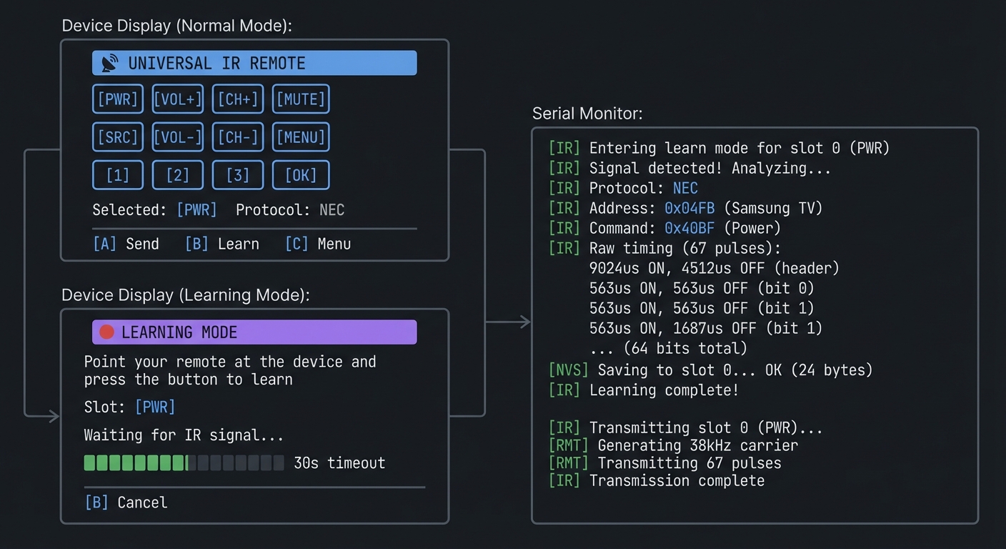
Example Output:
Device Display (Normal Mode):
┌──────────────────────────────────────────────┐
│       📡 UNIVERSAL IR REMOTE                 │
├──────────────────────────────────────────────┤
│                                              │
│   [PWR]   [VOL+]   [CH+]   [MUTE]           │
│                                              │
│   [SRC]   [VOL-]   [CH-]   [MENU]           │
│                                              │
│   [1]     [2]      [3]     [OK]             │
│                                              │
│   Selected: [PWR]   Protocol: NEC           │
│   [A] Send    [B] Learn     [C] Menu        │
└──────────────────────────────────────────────┘

Device Display (Learning Mode):
┌──────────────────────────────────────────────┐
│       🔴 LEARNING MODE                       │
├──────────────────────────────────────────────┤
│                                              │
│   Point your remote at the device            │
│   and press the button to learn              │
│                                              │
│   Slot: [PWR]                                │
│                                              │
│   Waiting for IR signal...                   │
│   ▓▓▓▓▓▓░░░░░░░░░░░░ 30s timeout            │
│                                              │
│   [B] Cancel                                 │
└──────────────────────────────────────────────┘

Serial Monitor:
[IR] Entering learn mode for slot 0 (PWR)
[IR] Signal detected! Analyzing...
[IR] Protocol: NEC
[IR] Address: 0x04FB (Samsung TV)
[IR] Command: 0x40BF (Power)
[IR] Raw timing (67 pulses):
     9024us ON, 4512us OFF  (header)
     563us ON, 563us OFF    (bit 0)
     563us ON, 1687us OFF   (bit 1)
     ... (64 bits total)
[NVS] Saving to slot 0... OK (24 bytes)
[IR] Learning complete!

[IR] Transmitting slot 0 (PWR)...
[RMT] Generating 38kHz carrier
[RMT] Transmitting 67 pulses
[IR] Transmission complete
The Core Question You’re Answering
“How do TV remotes encode button presses into invisible light pulses, and how can you decode and recreate these signals?”
Before you write any code, sit with this question. An IR remote sends nothing but flashes of 940nm light—invisible to humans but visible to cameras. Yet somehow, your TV knows the difference between “Volume Up” and “Channel Down” from these flashes. The answer is timing—precisely timed bursts encode binary data.
Concepts You Must Understand First
Stop and research these before coding:
- Pulse Distance/Width Modulation
- What is a “mark” and a “space” in IR communication?
- How does NEC encode a 0 vs a 1?
- Why is the carrier frequency 38kHz?
- Reference: SB-Projects IR Remote Control Theory
- The NEC Protocol
- What does a complete NEC message look like?
- What are the address and command fields?
- Why does NEC send inverted copies of address and command?
- How does NEC repeat work (vs sending the full code again)?
- Reference: SB-Projects NEC Protocol Specification
- ESP32 RMT Peripheral
- What is RMT and why is it better than bit-banging GPIO?
- How does RMT handle microsecond-precision timing?
- How does RMT generate the 38kHz carrier signal?
- Reference: ESP-IDF RMT Documentation
Questions to Guide Your Design
Before implementing, think through these:
- Learning Mode
- How will you detect the start of an IR signal?
- How long should you wait before timing out?
- How do you distinguish signal from noise?
- Protocol Detection
- NEC uses a 9ms header, Sony uses 2.4ms—how will you tell them apart?
- Should you store raw timings or decode to protocol format?
- What if you encounter an unknown protocol?
- Storage
- How much data does one IR code require?
- How many codes can you fit in flash?
- Should you use NVS, SPIFFS, or raw flash partitions?
Thinking Exercise
Decode an NEC Signal by Hand
Given this timing sequence (in microseconds):
9000 ON, 4500 OFF,   <- Header
560 ON, 560 OFF,     <- Bit 0 (logical 0)
560 ON, 1690 OFF,    <- Bit 1 (logical 1)
560 ON, 560 OFF,     <- Bit 2 (logical 0)
560 ON, 1690 OFF,    <- Bit 3 (logical 1)
... (60 more bits)
560 ON               <- Stop bit
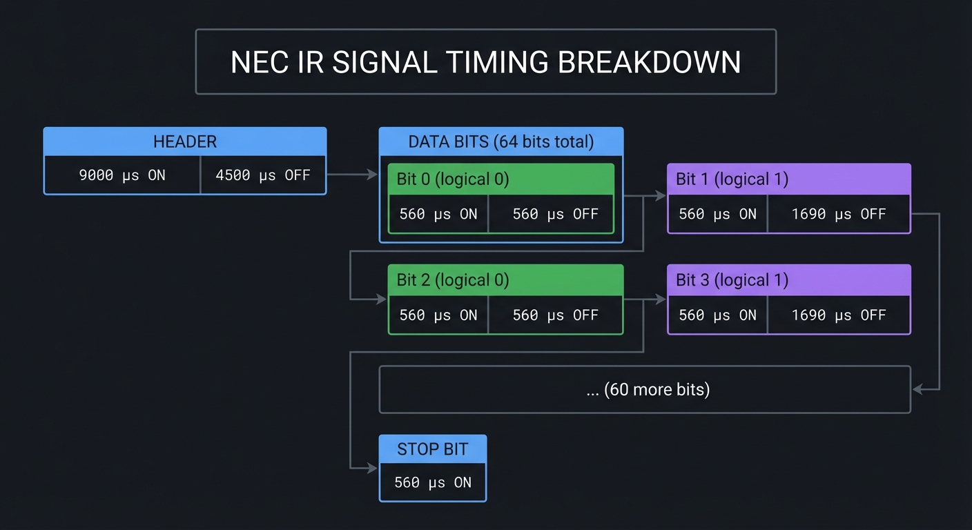
Questions while decoding:
- The header is always 9ms ON + 4.5ms OFF. How would you detect this programmatically?
- A short space (560µs) means 0, a long space (1690µs) means 1. Why not use ON time instead?
- 32 bits total: 8 address + 8 address_inverse + 8 command + 8 command_inverse. Why send inverses?
- If you receive
0x04 0xFB 0x40 0xBF, what are the address and command? (Answer: address=0x04, command=0x40)
The Interview Questions They’ll Ask
Prepare to answer these:
- “Explain how NEC infrared encoding works at the bit level.”
- “Why do IR remotes use a 38kHz carrier frequency?”
- “How would you implement a timeout when waiting for IR signals?”
- “What are the advantages of using a hardware peripheral (RMT) vs bit-banging GPIO?”
- “How would you store configuration data persistently on an ESP32?”
Hints in Layers
Hint 1: Start With Receiving Use an IR receiver module (like VS1838B) on a Grove port. The IRremoteESP8266 library can decode common protocols automatically.
Hint 2: Understand Raw Mode When decoding, capture raw timings first. You can analyze protocol later. Store an array of microsecond values for each mark/space.
Hint 3: Transmitting The StickC Plus2 has a built-in IR LED on GPIO9. For NEC transmission, you need to generate a 38kHz PWM carrier, then modulate it with your timing sequence.
Hint 4: RMT Configuration ESP32’s RMT can handle both receiving and transmitting. For TX, configure carrier frequency and pulse patterns. For RX, set up the receiver to capture edges.
Common Pitfalls & Debugging
Problem: “IR codes do not trigger target device”
- Why: Wrong carrier frequency or timing
- Fix: Match protocol timing and 38kHz carrier
- Quick test: Measure output with a phone camera or IR receiver
Problem: “Learning mode returns inconsistent codes”
- Why: Noisy signal or incorrect sampling
- Fix: Average multiple captures and use proper gap detection
- Quick test: Capture the same remote 5x and compare hashes
Definition of Done
- Learns and replays at least 5 IR codes
- Protocol decoding identifies common formats
- Codes persist across reboot (NVS)
- UI allows test-send and delete
Books That Will Help
| Topic | Book | Chapter |
|---|---|---|
| Timing-critical I/O | “Making Embedded Systems” by Elecia White | Ch. 5 |
| Hardware peripherals | ESP32 Technical Reference Manual | Ch. 15 (RMT) |
| Data persistence | “Making Embedded Systems” by Elecia White | Ch. 9 |
| Signal processing | “The Art of Electronics” by Horowitz & Hill | Ch. 10 |
Implementation Hints
The key insight is that IR transmission is really about precise timing. The ESP32’s RMT peripheral exists specifically for this—it can generate timing patterns with microsecond accuracy while your CPU does other things.
For learning mode:
- Configure RMT in receive mode
- Wait for signal (edge detection)
- Capture all timing pairs until gap > 20ms
- Analyze header to identify protocol
- Decode bits based on protocol rules
For transmitting:
- Build RMT item array with timing pairs
- Configure carrier (38kHz, 33% duty cycle)
- Send and wait for completion
Store learned codes using ESP32’s NVS (Non-Volatile Storage) library—it handles wear leveling and provides a key-value API.
Learning milestones:
- You can read and print raw IR timings → You understand signal capture
- You can decode NEC address and command → You understand the protocol
- Your device can control a real TV → You’ve mastered IR transmission
Project 4: Motion-Activated Smart Watch with Gesture Control (IMU Mastery)
- File: LEARN_M5STACK_STICKC_PLUS2_DEEP_DIVE.md
- Main Programming Language: C++ (Arduino)
- Alternative Programming Languages: MicroPython, CircuitPython
- Coolness Level: Level 4: Hardcore Tech Flex
- Business Potential: 2. The “Micro-SaaS / Pro Tool”
- Difficulty: Level 3: Advanced
- Knowledge Area: IMU Sensors, Gesture Recognition, Signal Processing
- Software or Tool: MPU6886, M5Unified, Watch accessories
- Main Book: “Making Embedded Systems, 2nd Edition” by Elecia White
What you’ll build: A wearable smart watch that wakes on wrist-raise, displays time/date/battery, recognizes gestures (shake to dismiss, tilt to scroll), and demonstrates how fitness trackers detect motion patterns.
Why it teaches sensor fusion: The IMU (accelerometer + gyroscope) is the core sensor in every fitness tracker, phone rotation, and game controller. You’ll learn to read raw sensor data, filter noise, detect events, and combine multiple axes into meaningful gestures—skills that transfer to any motion-sensing project.
Core challenges you’ll face:
- Calibrating the IMU at startup → maps to sensor offset and drift correction
- Detecting orientation from acceleration → maps to gravity vector decomposition
- Recognizing gestures from motion patterns → maps to state machines and threshold detection
- Minimizing power while monitoring motion → maps to sampling strategies and interrupts
Key Concepts:
- Accelerometer Physics: Making Embedded Systems Ch. 7 - Elecia White
- Sensor Calibration: MPU6886 datasheet - TDK InvenSense
- Low-Pass Filtering: The Art of Electronics Ch. 8 - Horowitz & Hill
- Power Optimization: Making Embedded Systems Ch. 10 - Elecia White
Difficulty: Advanced Time estimate: 2 weeks Prerequisites: Projects 1-2 completed, basic trigonometry, understanding of 3D coordinate systems
Real World Outcome
You’ll have a functional smart watch with:
- Always-on clock that wakes on wrist-raise gesture
- Gesture recognition for navigation (tilt, shake, tap)
- Step counter demonstration
- Orientation visualization
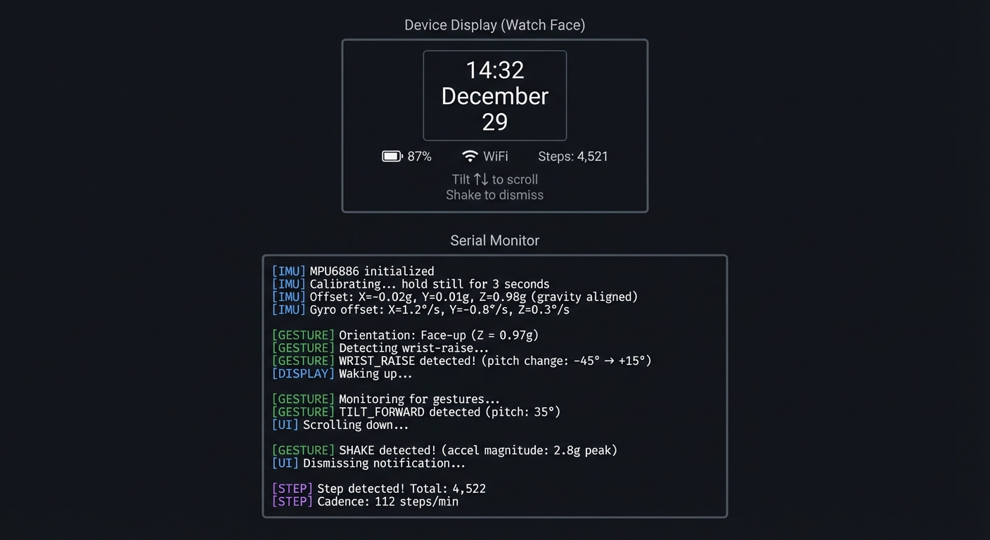
Example Output:
Device Display (Watch Face):
┌──────────────────────────────────────────────┐
│                                              │
│              ┌─────────────┐                 │
│              │   14:32     │                 │
│              │  December   │                 │
│              │     29      │                 │
│              └─────────────┘                 │
│                                              │
│     🔋 87%     📶 WiFi     Steps: 4,521      │
│                                              │
│   Tilt ↑↓ to scroll    Shake to dismiss     │
└──────────────────────────────────────────────┘

Serial Monitor:
[IMU] MPU6886 initialized
[IMU] Calibrating... hold still for 3 seconds
[IMU] Offset: X=-0.02g, Y=0.01g, Z=0.98g (gravity aligned)
[IMU] Gyro offset: X=1.2°/s, Y=-0.8°/s, Z=0.3°/s

[GESTURE] Orientation: Face-up (Z = 0.97g)
[GESTURE] Detecting wrist-raise...
[GESTURE] WRIST_RAISE detected! (pitch change: -45° → +15°)
[DISPLAY] Waking up...

[GESTURE] Monitoring for gestures...
[GESTURE] TILT_FORWARD detected (pitch: 35°)
[UI] Scrolling down...

[GESTURE] SHAKE detected! (accel magnitude: 2.8g peak)
[UI] Dismissing notification...

[STEP] Step detected! Total: 4,522
[STEP] Cadence: 112 steps/min
The Core Question You’re Answering
“How do smartphones and fitness trackers know which way they’re oriented and detect motion patterns like steps or gestures?”
Before you write any code, sit with this question. Your phone knows when you rotate it. Your fitness tracker counts steps. Your game controller knows when you swing it. All of this comes from a tiny chip measuring acceleration and rotation—but the raw data is noisy, ambiguous, and needs interpretation.
Concepts You Must Understand First
Stop and research these before coding:
- Accelerometer Basics
- What does an accelerometer actually measure (hint: not just motion)?
- Why does a stationary device read ~1g on one axis?
- How do you separate gravity from actual acceleration?
- Book Reference: “Making Embedded Systems” Ch. 7 - Elecia White
- Gyroscope and Integration
- What does a gyroscope measure (angular velocity, not angle)?
- Why does integrating gyro data lead to drift?
- What is sensor fusion and why is it needed?
- Reference: MPU6886 Application Note - TDK InvenSense
- Digital Filtering
- What is a low-pass filter and why is it needed?
- How do you implement a simple moving average?
- What is an exponential moving average (EMA)?
- Book Reference: “The Art of Electronics” Ch. 8 - Horowitz & Hill
Questions to Guide Your Design
Before implementing, think through these:
- Orientation Detection
- If the device is tilted 45°, what will the X, Y, Z acceleration values be?
- How do you calculate pitch and roll from accelerometer readings?
- What happens to your calculation if the device is being shaken?
- Gesture Recognition
- How will you distinguish a “shake” from normal arm movement?
- What defines a “wrist raise” gesture?
- How do you avoid false positives while still being responsive?
- Power Management
- Should you sample the IMU continuously or use interrupts?
- What sample rate is needed for gesture detection vs step counting?
- How can you put the IMU into low-power mode when the display is off?
Thinking Exercise
Calculate Orientation from Gravity
The accelerometer at rest reads: X = 0.12g, Y = -0.05g, Z = 0.99g
Questions to work through:
- Is this device “upright” or tilted? How do you know?
- Calculate the pitch angle: pitch = atan2(Y, sqrt(X² + Z²))
- Calculate the roll angle: roll = atan2(X, Z)
- If Z were negative, what would that mean about device orientation?
- The values don’t add to exactly 1g—why might that be?
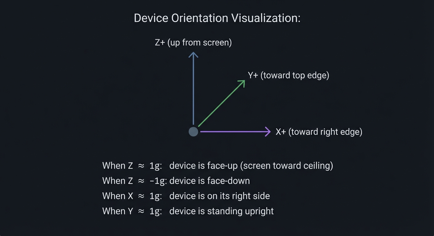
Device Orientation Visualization:

       Z+ (up from screen)
        ▲
        │
        │    Y+ (toward top edge)
        │   ╱
        │  ╱
        │ ╱
        ●───────► X+ (toward right edge)

When Z ≈ 1g: device is face-up (screen toward ceiling)
When Z ≈ -1g: device is face-down
When X ≈ 1g: device is on its right side
When Y ≈ 1g: device is standing upright
The Interview Questions They’ll Ask
Prepare to answer these:
- “How does an accelerometer work and what does it actually measure?”
- “Explain how you would implement step detection using an accelerometer.”
- “What is sensor fusion and why is it important for orientation tracking?”
- “How would you filter noisy sensor data in a resource-constrained environment?”
- “Describe the tradeoffs between sampling rate and power consumption for motion sensors.”
Hints in Layers
Hint 1: Start With Raw Data Use M5.Imu.getAccelData() to read accelerometer values. Print them continuously and move the device to understand what each axis represents.
Hint 2: Calibrate at Startup The MPU6886 has manufacturing offsets. At startup, with device stationary, read 100 samples and compute the average—this is your offset. Subtract it from all future readings.
Hint 3: Implement Low-Pass Filter
For smooth orientation, use EMA: filtered = alpha * new_value + (1 - alpha) * filtered. Try alpha = 0.1 for stable readings.
Hint 4: Gesture State Machine Don’t just check thresholds—use states. For wrist-raise: (1) arm down (pitch < -30°), (2) arm rising (pitch increasing), (3) arm up (pitch > 0°). Only trigger on the full sequence.
Common Pitfalls & Debugging
Problem: “Gesture detection is unstable”
- Why: Gyro drift or no filtering
- Fix: Calibrate on startup and apply low-pass filter
- Quick test: Hold device still and verify bias goes to zero
Problem: “Watch wakes too often”
- Why: Wake thresholds too sensitive
- Fix: Tune motion threshold and add debounce
- Quick test: Log wake events over 1 hour and review rate
Definition of Done
- Gesture detection works with calibrated IMU
- Wake-on-motion works with debounce
- Display updates without lag during motion
- Battery life improved vs always-on
Books That Will Help
| Topic | Book | Chapter |
|---|---|---|
| Sensor physics | “Making Embedded Systems” by Elecia White | Ch. 7 |
| Signal filtering | “The Art of Electronics” by Horowitz & Hill | Ch. 8 |
| Power optimization | “Making Embedded Systems” by Elecia White | Ch. 10 |
| Motion algorithms | “Programming Embedded Systems” by Barr & Massa | Ch. 10 |
Implementation Hints
The key insight is that gesture recognition is a state machine, not a simple threshold check. A shake isn’t just “acceleration > 2g”—it’s “acceleration crossed threshold, then crossed back, multiple times within 500ms.”
For wrist-raise detection:
- Track pitch angle over time
- State IDLE: waiting for arm-down position (pitch < -30°)
- State RISING: pitch is increasing
- State TRIGGERED: pitch crossed into viewing range (pitch > 0°)
For step counting, look for periodic peaks in the accelerometer magnitude:
- Compute magnitude: sqrt(x² + y² + z²)
- Detect peaks (local maxima above threshold)
- Filter by time between peaks (humans walk at 0.5-3 Hz)
Learning milestones:
- You can read and print stable orientation (pitch/roll) → You understand accelerometer interpretation
- Wrist-raise wakes the display reliably → You understand gesture state machines
- Step counter matches actual steps within 10% → You understand signal processing
Project 5: BLE Beacon Proximity Scanner (Bluetooth Low Energy)
- File: LEARN_M5STACK_STICKC_PLUS2_DEEP_DIVE.md
- Main Programming Language: C++ (Arduino)
- Alternative Programming Languages: ESP-IDF (C), MicroPython
- Coolness Level: Level 4: Hardcore Tech Flex
- Business Potential: 3. The “Service & Support” Model
- Difficulty: Level 3: Advanced
- Knowledge Area: BLE Protocol, iBeacon, Proximity Detection
- Software or Tool: ESP32 BLE library, iBeacon protocol
- Main Book: “Getting Started with Bluetooth Low Energy” by Townsend (O’Reilly)
What you’ll build: A BLE scanner that detects nearby iBeacon and Eddystone beacons, estimates distance based on signal strength, and can also broadcast as a beacon itself—demonstrating the technology behind asset tracking, indoor navigation, and proximity marketing.
Why it teaches wireless protocols: BLE is fundamentally different from WiFi—it’s designed for low power, not high bandwidth. You’ll understand advertising packets, RSSI-to-distance conversion, and how retail stores know when you’re near a product display.
Core challenges you’ll face:
- Understanding BLE advertising vs connected modes → maps to protocol stack design
- Parsing iBeacon packet format → maps to binary protocol parsing
- Estimating distance from RSSI → maps to RF propagation and signal processing
- Implementing beacon broadcasting → maps to constructing protocol packets
Key Concepts:
- BLE Architecture: Getting Started with Bluetooth Low Energy Ch. 2 - Townsend
- iBeacon Protocol: Apple iBeacon Specification
- RSSI and Path Loss: Computer Networks Ch. 2 - Tanenbaum
- Advertising Packets: ESP32 BLE documentation - Espressif
Difficulty: Advanced Time estimate: 1-2 weeks Prerequisites: Understanding of binary/hex, some networking concepts
Real World Outcome
You’ll have a handheld BLE scanner that:
- Scans for and displays nearby BLE devices
- Parses iBeacon UUID, major, minor values
- Estimates distance from RSSI
- Can switch to beacon mode and broadcast
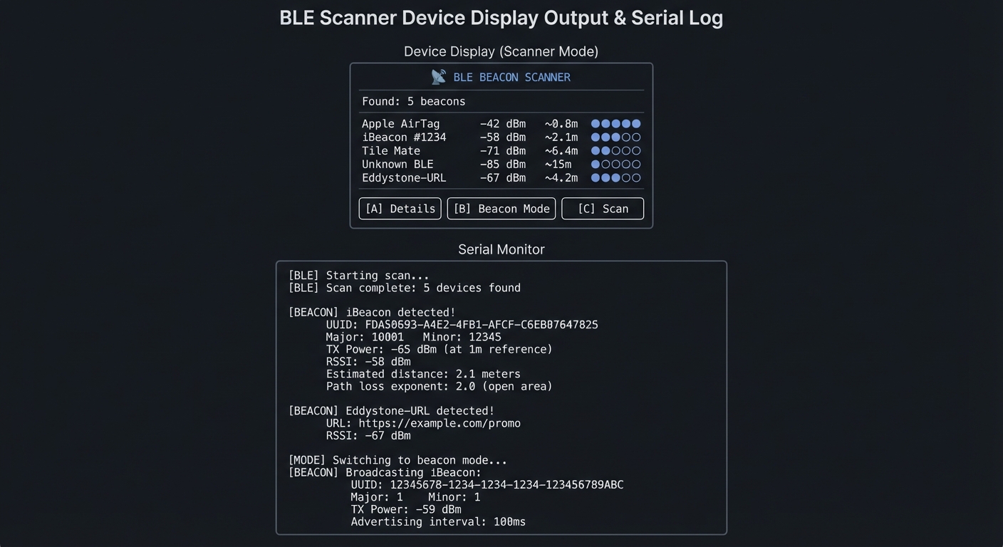
Example Output:
Device Display (Scanner Mode):
┌──────────────────────────────────────────────┐
│       📡 BLE BEACON SCANNER                  │
├──────────────────────────────────────────────┤
│                                              │
│   Found: 5 beacons                           │
│                                              │
│   1. Apple AirTag     -42 dBm  ~0.8m  ●●●●○  │
│   2. iBeacon #1234    -58 dBm  ~2.1m  ●●●○○  │
│   3. Tile Mate        -71 dBm  ~6.4m  ●●○○○  │
│   4. Unknown BLE      -85 dBm  ~15m   ●○○○○  │
│   5. Eddystone-URL    -67 dBm  ~4.2m  ●●○○○  │
│                                              │
│   [A] Details    [B] Beacon Mode    [C] Scan │
└──────────────────────────────────────────────┘

Serial Monitor:
[BLE] Starting scan...
[BLE] Scan complete: 5 devices found

[BEACON] iBeacon detected!
  UUID: FDA50693-A4E2-4FB1-AFCF-C6EB07647825
  Major: 10001    Minor: 12345
  TX Power: -65 dBm (at 1m reference)
  RSSI: -58 dBm
  Estimated distance: 2.1 meters
  Path loss exponent: 2.0 (open area)

[BEACON] Eddystone-URL detected!
  URL: https://example.com/promo
  RSSI: -67 dBm

[MODE] Switching to beacon mode...
[BEACON] Broadcasting iBeacon:
  UUID: 12345678-1234-1234-1234-123456789ABC
  Major: 1    Minor: 1
  TX Power: -59 dBm
  Advertising interval: 100ms
The Core Question You’re Answering
“How do stores know when you’re standing near a specific product, and how does indoor positioning work without GPS?”
Before you write any code, sit with this question. GPS doesn’t work indoors. Yet museums can trigger audio guides as you approach exhibits, and retailers can send you coupons when you’re near a product. BLE beacons are the technology enabling this—and understanding them teaches you about wireless protocols, signal propagation, and proximity estimation.
Concepts You Must Understand First
Stop and research these before coding:
- BLE Advertising
- What is the difference between advertising and connected modes?
- How often do beacons advertise (interval)?
- What data can fit in an advertising packet (31 bytes)?
- Book Reference: “Getting Started with Bluetooth Low Energy” Ch. 2
- iBeacon Packet Format
- What are the 16-byte UUID, 2-byte major, and 2-byte minor values?
- What is the 1-byte TX Power field and what does it represent?
- How do you identify an iBeacon from a generic BLE advertisement?
- Reference: Apple iBeacon specification
- RSSI and Distance Estimation
- What is RSSI and how is it measured?
- Why is the relationship between RSSI and distance logarithmic?
- What is the path loss exponent and how does it vary by environment?
- Book Reference: “Computer Networks” Ch. 2 - Tanenbaum
Questions to Guide Your Design
Before implementing, think through these:
- Scanning Strategy
- Should you scan continuously or periodically?
- How do you handle the same beacon appearing in multiple scans?
- How do you detect when a beacon has gone out of range?
- Distance Accuracy
- RSSI fluctuates by ±10 dBm—how do you smooth it?
- What environment factors affect signal strength?
- Is precise distance really achievable, or just proximity zones?
- Power vs Responsiveness
- Scanning uses significant power—how do you balance detection speed vs battery?
- In beacon mode, how does advertising interval affect power and detectability?
Thinking Exercise
Parse an iBeacon Packet
Given this raw advertising data (hex):
02 01 06 1A FF 4C 00 02 15
E2 C5 6D B5 DF FB 48 D2 B0 60 D0 F5 A7 10 96 E0
00 01 00 02 C5
Questions to decode:
- Bytes 5-6 are company ID (0x004C). Whose company ID is this? (Answer: Apple)
- Bytes 7-8 are beacon type (0x0215). What does 0x15 mean? (Answer: iBeacon, 21 bytes following)
- Bytes 9-24 are the UUID. Extract it in standard format (8-4-4-4-12)
- Bytes 25-26 are Major. What value? (Answer: 0x0001 = 1)
- Bytes 27-28 are Minor. What value? (Answer: 0x0002 = 2)
- Byte 29 is TX Power. If it’s 0xC5, what’s the signed value? (Answer: -59 dBm)
The Interview Questions They’ll Ask
Prepare to answer these:
- “Explain the difference between BLE advertising and connection modes.”
- “How would you estimate the distance to a BLE beacon using RSSI?”
- “What are the practical limitations of BLE-based indoor positioning?”
- “Compare iBeacon with Eddystone. What are the tradeoffs?”
- “How would you optimize power consumption in a BLE scanning application?”
Hints in Layers
Hint 1: Use the ESP32 BLE Library
Install ESP32 BLE library. Start with the “BLE_scan” example. The BLEAdvertisedDeviceCallbacks class receives every detected device.
Hint 2: Identify iBeacons
In the callback, check if getManufacturerData() starts with 4C 00 02 15. If so, it’s an Apple iBeacon. Parse the following 21 bytes.
Hint 3: Calculate Distance Use the log-distance path loss model:
distance = 10 ^ ((txPower - rssi) / (10 * n))
where n is the path loss exponent (typically 2.0 in open areas, 3.0-4.0 indoors).
Hint 4: Smooth RSSI RSSI fluctuates significantly. Use a Kalman filter or simple moving average over 5-10 readings to get stable distance estimates.
Common Pitfalls & Debugging
Problem: “BLE scanner misses nearby devices”
- Why: Scan window/interval too short
- Fix: Increase scan window or use active scanning
- Quick test: Compare results with a phone BLE scanner
Problem: “RSSI values jump wildly”
- Why: No smoothing or poor antenna orientation
- Fix: Apply exponential moving average and clamp spikes
- Quick test: Log RSSI and verify smoothing reduces variance
Definition of Done
- Detects and lists nearby BLE devices
- RSSI smoothing produces stable distance estimate
- Scan interval and window are configurable
- Exportable log of sightings exists
Books That Will Help
| Topic | Book | Chapter |
|---|---|---|
| BLE fundamentals | “Getting Started with Bluetooth Low Energy” | Ch. 1-3 |
| Signal propagation | “Computer Networks” by Tanenbaum | Ch. 2 |
| ESP32 BLE | ESP32 Programming Guide | BLE section |
| Indoor positioning | “Location-Based Services” by Schiller | Ch. 4 |
Implementation Hints
The key insight is that BLE advertising is broadcast—no connection needed. This makes it perfect for one-way information transmission (beacons) and discovery.
For scanning:
- Create
BLEScanobject with callback - Set active scan for more data (optional)
- Start scan for N seconds
- Process results in callback
For parsing iBeacons:
- Check manufacturer data exists and has correct prefix
- Extract UUID (bytes 4-19), Major (20-21), Minor (22-23), TX Power (24)
- Remember TX Power is signed byte
For beacon broadcasting:
- Create
BLEAdvertisementDatawith iBeacon prefix - Add your UUID, Major, Minor, TX Power
- Start advertising with desired interval
Learning milestones:
- You can scan and list all nearby BLE devices → You understand BLE advertising
- You can parse iBeacon data and display UUID/Major/Minor → You understand packet formats
- Your device can broadcast as a beacon and be detected by phone apps → You understand both directions
Project 6: Battery-Optimized Data Logger with Deep Sleep (Power Management)
- File: LEARN_M5STACK_STICKC_PLUS2_DEEP_DIVE.md
- Main Programming Language: C++ (Arduino)
- Alternative Programming Languages: ESP-IDF (C), MicroPython
- Coolness Level: Level 3: Genuinely Clever
- Business Potential: 3. The “Service & Support” Model
- Difficulty: Level 3: Advanced
- Knowledge Area: Power Management, Deep Sleep, RTC Memory
- Software or Tool: ESP32 sleep APIs, BM8563 RTC
- Main Book: “Making Embedded Systems, 2nd Edition” by Elecia White
What you’ll build: A data logger that samples environmental data at configurable intervals, stores readings in flash, and achieves weeks of battery life through aggressive deep sleep—demonstrating production-grade power optimization techniques.
Why it teaches power management: The 200mAh battery lasts about 50 minutes at full power. Yet commercial IoT sensors run for months on similar batteries. The secret is deep sleep—and understanding exactly what power is consumed where. This project teaches you to think about every microamp.
Core challenges you’ll face:
- Configuring ESP32 deep sleep modes → maps to understanding power domains
- Persisting data across sleep cycles → maps to RTC memory and flash storage
- Using RTC for precise wake timing → maps to low-power timekeeping
- Optimizing wake time → maps to minimizing active power consumption
Key Concepts:
- ESP32 Power Modes: ESP32 Technical Reference Manual - Espressif
- RTC Memory: Making Embedded Systems Ch. 10 - Elecia White
- Flash Wear Leveling: Making Embedded Systems Ch. 9 - Elecia White
- Current Measurement: The Art of Electronics Ch. 15 - Horowitz & Hill
Difficulty: Advanced Time estimate: 1-2 weeks Prerequisites: Projects 1-2 completed, understanding of ESP32 memory architecture
Real World Outcome
You’ll have a long-running data logger that:
- Wakes at configurable intervals (1 min to 24 hours)
- Samples sensors quickly (<1 second wake time)
- Stores data in flash with timestamps
- Displays accumulated data on button press
- Runs for weeks on a single charge
Example Output:
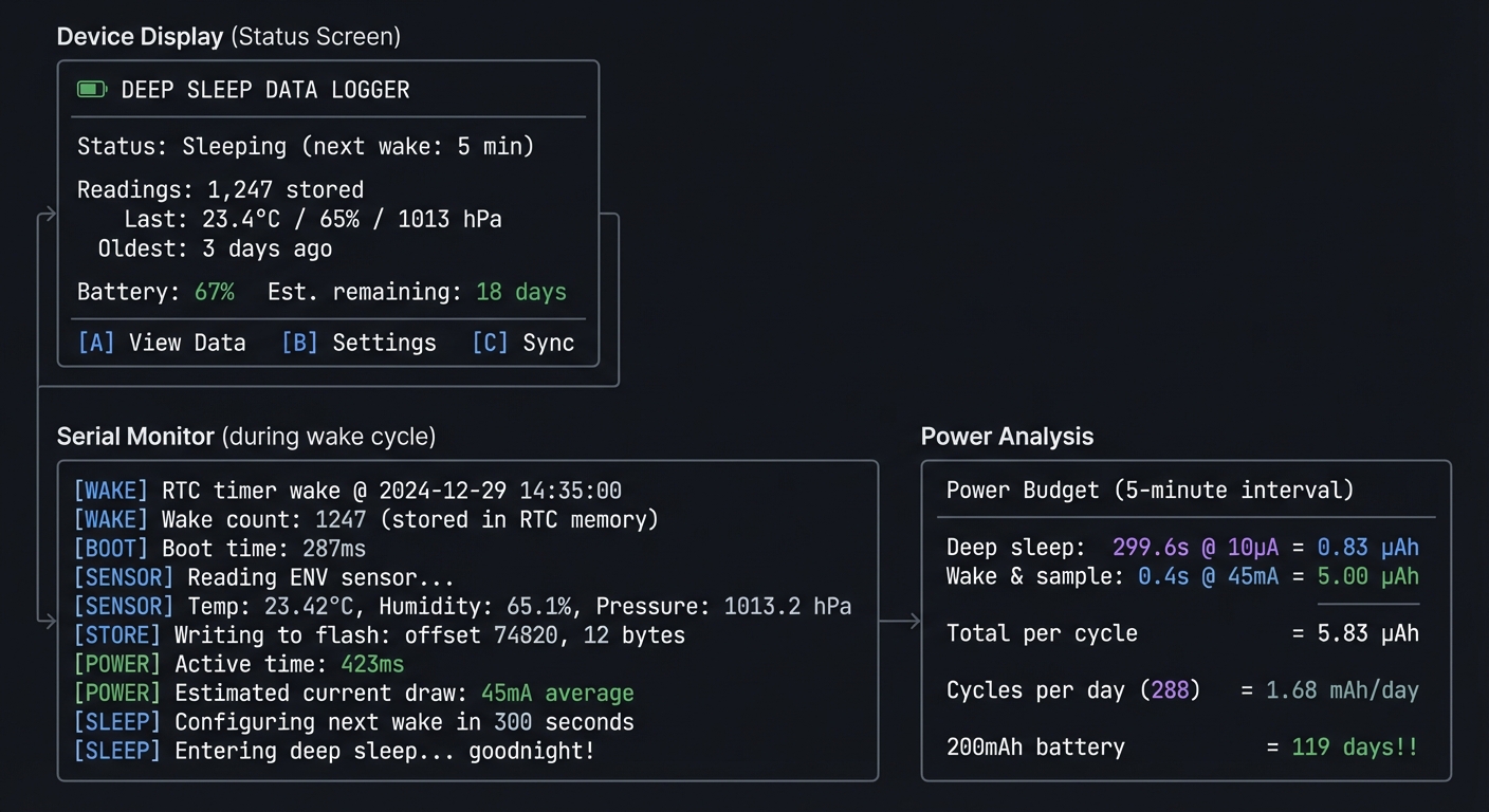
Device Display (Status Screen):
┌──────────────────────────────────────────────┐
│       🔋 DEEP SLEEP DATA LOGGER              │
├──────────────────────────────────────────────┤
│                                              │
│   Status: Sleeping (next wake: 5 min)        │
│                                              │
│   Readings: 1,247 stored                     │
│   Last: 23.4°C / 65% / 1013 hPa              │
│   Oldest: 3 days ago                         │
│                                              │
│   Battery: 67%   Est. remaining: 18 days     │
│                                              │
│   [A] View Data    [B] Settings    [C] Sync  │
└──────────────────────────────────────────────┘

Serial Monitor (during wake cycle):
[WAKE] RTC timer wake @ 2024-12-29 14:35:00
[WAKE] Wake count: 1247 (stored in RTC memory)
[BOOT] Boot time: 287ms
[SENSOR] Reading ENV sensor...
[SENSOR] Temp: 23.42°C, Humidity: 65.1%, Pressure: 1013.2 hPa
[STORE] Writing to flash: offset 74820, 12 bytes
[POWER] Active time: 423ms
[POWER] Estimated current draw: 45mA average
[SLEEP] Configuring next wake in 300 seconds
[SLEEP] Entering deep sleep... goodnight!

[Power Analysis]:
┌──────────────────────────────────────────────┐
│ Power Budget (5-minute interval)             │
├──────────────────────────────────────────────┤
│ Deep sleep: 299.6s @ 10µA    = 0.83 µAh      │
│ Wake & sample: 0.4s @ 45mA   = 5.00 µAh      │
│ Total per cycle              = 5.83 µAh      │
│ Cycles per day (288)         = 1.68 mAh/day  │
│ 200mAh battery               = 119 days!!    │
└──────────────────────────────────────────────┘
The Core Question You’re Answering
“How do battery-powered IoT devices run for months or years on tiny batteries?”
Before you write any code, sit with this question. A 200mAh battery at 50mA active current lasts 4 hours. Yet commercial sensors last years. The key is duty cycling—spending 99.9% of time in deep sleep drawing microamps, not milliamps. Every optimization matters: boot speed, sensor read time, WiFi connection time.
Concepts You Must Understand First
Stop and research these before coding:
- ESP32 Power Domains
- What components are powered in each sleep mode?
- What’s the difference between light sleep and deep sleep?
- What is the ULP coprocessor and when would you use it?
- Book Reference: ESP32 Technical Reference Manual Ch. 29
- RTC Memory Persistence
- What is RTC_DATA_ATTR and how does it survive deep sleep?
- How much RTC memory is available?
- When is RTC memory erased (hint: reset button)?
- Book Reference: “Making Embedded Systems” Ch. 10 - Elecia White
- Wake Sources
- What can wake the ESP32 from deep sleep?
- How do you configure timer-based wake?
- How do you configure GPIO-based wake (button press)?
- Reference: ESP-IDF Deep Sleep documentation
Questions to Guide Your Design
Before implementing, think through these:
- Wake Strategy
- Should you use ESP32’s internal timer or the BM8563 RTC?
- What if you want to wake on button press AND timer?
- How do you know WHY the device woke up?
- Data Storage
- How many readings can you store before running out of flash?
- How do you handle flash wear (limited write cycles)?
- When do you upload/clear stored data?
- Power Measurement
- How will you measure actual sleep current?
- What peripherals are you leaving powered accidentally?
- Is the display backlight fully off during sleep?
Thinking Exercise
Calculate Your Power Budget
Fill in this table for your design:
| Phase           | Duration | Current | Charge Used |
|-----------------|----------|---------|-------------|
| Deep sleep      | 299.5s   | 10µA    | ?           |
| Boot/init       | 0.3s     | 50mA    | ?           |
| Sensor read     | 0.1s     | 30mA    | ?           |
| Flash write     | 0.05s    | 50mA    | ?           |
| Display update  | 0.05s    | 80mA    | ?           |
| TOTAL per cycle |          |         | ?           |
Questions to calculate:
- Charge (µAh) = Current (µA) × Time (hours)
- How many cycles per day if you sample every 5 minutes?
- Total daily consumption in mAh?
- Days of operation from 200mAh battery?
- What dominates: sleep power or active power?
The Interview Questions They’ll Ask
Prepare to answer these:
- “Explain the different power modes of the ESP32 and when you’d use each.”
- “How would you measure the actual power consumption of an embedded device?”
- “What techniques would you use to minimize wake time in a battery-powered sensor?”
- “How does RTC memory differ from regular RAM? What survives deep sleep?”
- “Design a system that runs for 2 years on a CR2032 coin cell.”
Hints in Layers
Hint 1: Start With Timer Wake
Use esp_sleep_enable_timer_wakeup(microseconds) to configure a timer wake. Start with 10 seconds to iterate quickly.
Hint 2: Preserve Data Across Sleep
Variables with RTC_DATA_ATTR survive deep sleep:
RTC_DATA_ATTR int bootCount = 0;
Use this for wake counts, accumulated data, etc.
Hint 3: GPIO Wake for User Interaction
Use esp_sleep_enable_ext0_wakeup(GPIO_NUM_X, LEVEL) to wake on button press. Check esp_sleep_get_wakeup_cause() to know if it was timer or button.
Hint 4: Minimize Boot Time The StickC Plus2 has a HOLD pin (GPIO4) that must be set HIGH to keep power on. Set it immediately in setup(). Also, skip WiFi initialization on sensor-only wakes.
Common Pitfalls & Debugging
Problem: “Deep sleep never wakes”
- Why: Wrong wake source or HOLD pin issue
- Fix: Configure GPIO/timer wake and keep HOLD pin high
- Quick test: Test wake with button press only
Problem: “Logged data corrupts over time”
- Why: Power loss during flash write
- Fix: Write in append-only pages and flush safely
- Quick test: Simulate power loss and verify last valid record
Definition of Done
- Device sleeps and wakes on schedule
- Logs timestamped data safely to flash
- Battery life estimate documented
- Data export works over USB or WiFi
Books That Will Help
| Topic | Book | Chapter |
|---|---|---|
| Power optimization | “Making Embedded Systems” by Elecia White | Ch. 10 |
| Flash storage | “Making Embedded Systems” by Elecia White | Ch. 9 |
| ESP32 sleep | ESP32 Technical Reference Manual | Ch. 29 |
| Current measurement | “The Art of Electronics” by Horowitz & Hill | Ch. 15 |
Implementation Hints
The key insight is that every millisecond of wake time matters when you’re optimizing for battery life. A 1-second vs 0.5-second wake time doubles your power consumption.
Optimization priorities:
- Skip unnecessary initialization on wake
- Don’t initialize WiFi unless you’re transmitting
- Read sensors with minimal delay
- Use fastest flash write settings
- Don’t update display unless user requested it
For persistent storage:
- Use SPIFFS or LittleFS for wear leveling
- Buffer multiple readings before writing
- Use binary format, not JSON, to save space
- Consider a circular buffer to handle full storage
For the HOLD pin (critical for StickC Plus2):
void setup() {
  pinMode(4, OUTPUT);
  digitalWrite(4, HIGH);  // MUST be first!
  // ...rest of init
}
Learning milestones:
- Device sleeps and wakes on timer → You understand deep sleep basics
- Boot count persists across sleep cycles → You understand RTC memory
- Device runs for days on battery → You’ve mastered power optimization
Project 7: Audio Spectrum Analyzer (I2S Microphone & DSP)
- File: LEARN_M5STACK_STICKC_PLUS2_DEEP_DIVE.md
- Main Programming Language: C++ (Arduino)
- Alternative Programming Languages: ESP-IDF (C), MicroPython
- Coolness Level: Level 4: Hardcore Tech Flex
- Business Potential: 2. The “Micro-SaaS / Pro Tool”
- Difficulty: Level 3: Advanced
- Knowledge Area: Digital Signal Processing, FFT, Audio Analysis
- Software or Tool: ArduinoFFT, ESP32 I2S, SPM1423 microphone
- Main Book: “The Scientist and Engineer’s Guide to Digital Signal Processing” by Smith
What you’ll build: A real-time audio spectrum analyzer that captures sound from the built-in microphone, performs FFT analysis, and displays frequency bars on screen—demonstrating digital signal processing fundamentals.
Why it teaches DSP: The Fast Fourier Transform (FFT) is one of the most important algorithms in computing, enabling everything from MP3 compression to voice recognition. You’ll see abstract math become tangible as sound waves transform into frequency bars on your display.
Core challenges you’ll face:
- Configuring I2S for audio input → maps to digital audio protocols
- Understanding sampling and Nyquist frequency → maps to signal theory fundamentals
- Implementing FFT and interpreting results → maps to frequency domain analysis
- Mapping frequency bins to visual display → maps to data visualization
Key Concepts:
- I2S Protocol: ESP32 Technical Reference Manual - Espressif
- Sampling Theory: DSP Guide Ch. 3 - Steven Smith
- FFT Algorithm: DSP Guide Ch. 12 - Steven Smith
- Audio Analysis: Making Embedded Systems Ch. 7 - Elecia White
Difficulty: Advanced Time estimate: 2 weeks Prerequisites: Basic understanding of signals, comfort with arrays, Projects 1 and 4 completed
Real World Outcome
You’ll have a pocket spectrum analyzer that:
- Captures audio in real-time from the microphone
- Performs FFT to extract frequency components
- Displays animated frequency bars
- Shows peak frequencies and dB levels
Example Output:
Device Display:
┌──────────────────────────────────────────────┐
│       🎵 AUDIO SPECTRUM ANALYZER             │
├──────────────────────────────────────────────┤
│                                              │
│   ▄     ▄                                    │
│   █ ▄   █ ▄       ▄                          │
│   █ █ ▄ █ █   ▄   █                          │
│   █ █ █ █ █ ▄ █ ▄ █ ▄     ▄                  │
│   █ █ █ █ █ █ █ █ █ █ ▄ ▄ █ ▄                │
│   █ █ █ █ █ █ █ █ █ █ █ █ █ █ ▄ ▄ ▄ ▄ ▄      │
│   ─────────────────────────────────────────  │
│   100  500  1k  2k  4k  8k  16k Hz          │
│                                              │
│   Peak: 440 Hz (A4)    Level: -24 dB        │
│   [A] Mode    [B] Scale    [C] Freeze       │
└──────────────────────────────────────────────┘

Serial Monitor:
[I2S] Configured: 44100 Hz, 16-bit, mono
[I2S] Buffer: 512 samples (11.6ms per frame)
[FFT] 512-point FFT, frequency resolution: 86.1 Hz
[FFT] Bin 0 (0 Hz): DC component
[FFT] Bin 5 (430 Hz): magnitude 1247 (strongest)
[FFT] Bin 6 (516 Hz): magnitude 892
[AUDIO] Peak frequency: 440 Hz (closest to A4)
[AUDIO] RMS level: -24.3 dB
[DISPLAY] FPS: 25
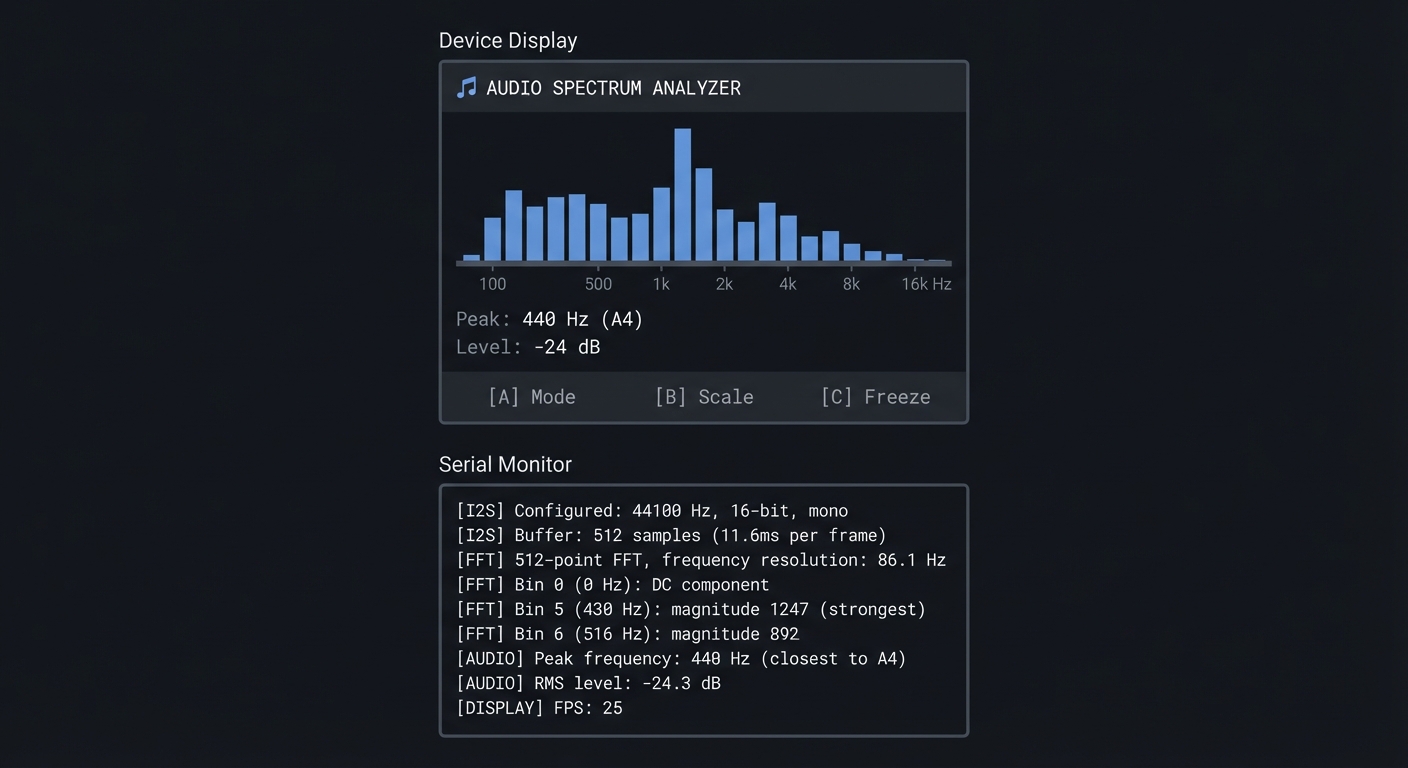
The Core Question You’re Answering
“How does software turn sound waves into frequency information, and why is the FFT called one of the most important algorithms ever invented?”
Before you write any code, sit with this question. When you play music, your ear perceives bass, midrange, and treble—separate frequency bands. But the microphone just sees a single voltage changing over time. The FFT mathematically decomposes that time-domain signal into its frequency components—and it does this so efficiently that real-time audio processing is possible on tiny microcontrollers.
Concepts You Must Understand First
Stop and research these before coding:
- Sampling and Nyquist
- What happens when you sample audio at 44.1 kHz?
- What is aliasing and how does sampling rate prevent it?
- If you can hear up to 20 kHz, what’s the minimum sampling rate?
- Book Reference: “DSP Guide” Ch. 3 - Steven Smith
- Time Domain vs Frequency Domain
- What does a sine wave look like in time domain? In frequency domain?
- If you add two sine waves, what does the spectrum look like?
- Why is frequency domain useful for audio analysis?
- Book Reference: “DSP Guide” Ch. 8 - Steven Smith
- FFT Basics
- How many output bins does an N-point FFT produce?
- What frequency does each bin represent?
- Why is the second half of FFT output redundant for real signals?
- Book Reference: “DSP Guide” Ch. 12 - Steven Smith
Questions to Guide Your Design
Before implementing, think through these:
- Sample Rate vs Resolution
- Higher sample rate = higher max frequency. What do you need for music?
- More samples per FFT = better frequency resolution. What’s the tradeoff?
- 512-sample FFT at 44.1 kHz: what’s your frequency resolution?
- Display Mapping
- How will you map 256 FFT bins to ~20 display bars?
- Should frequency axis be linear or logarithmic (like human hearing)?
- How will you scale magnitude to bar height?
- Smoothing
- FFT output changes rapidly—how do you make display readable?
- Should bars fall slowly (like physical analyzers)?
- How do you highlight peak frequencies?
Thinking Exercise
Calculate FFT Parameters
Given: sample_rate = 44100 Hz, FFT_size = 512 samples
Work through these:
- Frame duration = FFT_size / sample_rate = ?
- Frequency resolution = sample_rate / FFT_size = ?
- Maximum frequency (Nyquist) = sample_rate / 2 = ?
- If bin[5] has the highest magnitude, what frequency is that?
- How many useful bins do you have (excluding negative frequencies)?
Frequency Bin Mapping:

Bin 0:   0 Hz (DC)
Bin 1:   86.1 Hz
Bin 2:   172.3 Hz
Bin 3:   258.4 Hz
...
Bin 255: 21,991 Hz (near Nyquist)
Bins 256-511: Mirror of 1-255 (ignore for real signals)
The Interview Questions They’ll Ask
Prepare to answer these:
- “Explain the Nyquist theorem and why it matters for digital audio.”
- “What is the FFT and how does it relate to the DFT?”
- “How would you detect a specific frequency in an audio stream?”
- “What’s the tradeoff between FFT size and frequency resolution?”
- “How would you implement a real-time audio level meter?”
Hints in Layers
Hint 1: Configure I2S The SPM1423 is a PDM microphone. Use ESP-IDF’s I2S driver with PDM mode. Start with 44100 Hz sample rate and 512-sample buffer.
Hint 2: Use ArduinoFFT
Install the ArduinoFFT library. It provides FFT.Windowing(), FFT.Compute(), and FFT.ComplexToMagnitude(). Apply a Hamming window before FFT to reduce spectral leakage.
Hint 3: Scale for Display
FFT magnitudes vary enormously. Use logarithmic scaling: display_height = log10(magnitude + 1) * scale_factor. This matches human perception of loudness.
Hint 4: Smooth the Bars
Instead of jumping to new values, use: bar[i] = max(new_value, bar[i] * 0.9). This creates a “falling” effect where peaks decay gradually.
Common Pitfalls & Debugging
Problem: “FFT output looks random”
- Why: Wrong sample rate or missing windowing
- Fix: Confirm I2S sample rate and apply Hann window
- Quick test: Generate a pure tone and verify a single peak
Problem: “Audio capture stutters”
- Why: Buffer underrun or CPU overload
- Fix: Use double buffering and reduce render load
- Quick test: Profile CPU usage while sampling
Definition of Done
- FFT shows correct peak for known tone
- Spectrum refresh is smooth and stable
- Audio sampling runs without buffer underrun
- CPU usage stays within target budget
Books That Will Help
| Topic | Book | Chapter |
|---|---|---|
| Sampling theory | “DSP Guide” by Steven Smith | Ch. 3 |
| FFT algorithm | “DSP Guide” by Steven Smith | Ch. 12 |
| I2S protocol | ESP32 Technical Reference Manual | Ch. 12 |
| Audio fundamentals | “Making Embedded Systems” by Elecia White | Ch. 7 |
Implementation Hints
The key insight is that FFT gives you magnitude and phase for each frequency bin, but for visualization you only need magnitude. Phase is irrelevant for spectrum display.
For the I2S microphone:
- Configure I2S in PDM mode (the SPM1423 is PDM, not PCM)
- Read samples into a buffer
- Convert PDM data to PCM values (the driver handles this)
For visualization:
- Apply window function (Hamming) to reduce edge effects
- Compute FFT
- Take magnitude of first half of bins (0 to N/2-1)
- Map to logarithmic frequency axis for display
- Apply smoothing for visual appeal
Musical note frequencies to test:
- A4 = 440 Hz (tuning fork standard)
- Middle C (C4) = 261.63 Hz
- One octave up = 2× frequency
Learning milestones:
- You can read and plot raw audio samples → You understand I2S input
- FFT shows a peak at correct frequency for test tones → You understand spectral analysis
- Display shows smooth, responsive frequency bars → You’ve mastered real-time DSP
Project 8: OTA Firmware Updater with Version Management (Secure Updates)
- File: LEARN_M5STACK_STICKC_PLUS2_DEEP_DIVE.md
- Main Programming Language: C++ (Arduino)
- Alternative Programming Languages: ESP-IDF (C)
- Coolness Level: Level 3: Genuinely Clever
- Business Potential: 4. The “Open Core” Infrastructure
- Difficulty: Level 3: Advanced
- Knowledge Area: OTA Updates, Partition Management, Security
- Software or Tool: ArduinoOTA, ESP32 partition table, HTTPS
- Main Book: “Making Embedded Systems, 2nd Edition” by Elecia White
What you’ll build: A robust over-the-air update system that can download and install new firmware from a web server, with version checking, rollback capability, and progress indication—essential for any deployed IoT device.
Why it teaches production IoT: You can’t physically access every deployed device to update firmware. OTA updates are essential for bug fixes, security patches, and new features. Understanding partitions, dual-app schemes, and update security is critical for real-world IoT.
Core challenges you’ll face:
- Understanding ESP32 partition schemes → maps to flash memory organization
- Implementing dual-app update pattern → maps to atomic update strategies
- Adding version checking and rollback → maps to update reliability
- Securing the update channel → maps to transport security
Key Concepts:
- Flash Partitioning: ESP-IDF Partition Tables documentation - Espressif
- OTA Update Flow: Making Embedded Systems Ch. 11 - Elecia White
- Update Security: ESP32 Secure Boot documentation - Espressif
- HTTPS Transport: ESP32 WiFi documentation - Espressif
Difficulty: Advanced Time estimate: 1-2 weeks Prerequisites: Project 2 completed (WiFi connectivity), understanding of flash memory
Real World Outcome
You’ll have a complete OTA update system that:
- Checks for updates on a web server
- Shows download progress on display
- Safely installs new firmware
- Can rollback if update fails
- Requires valid firmware signatures (optional)
Example Output:
Device Display (Update Available):
┌──────────────────────────────────────────────┐
│       🔄 FIRMWARE UPDATE                     │
├──────────────────────────────────────────────┤
│                                              │
│   Current: v1.2.3                            │
│   Available: v1.3.0                          │
│                                              │
│   Changelog:                                 │
│   • Fixed battery percentage bug             │
│   • Added new gesture: double-tap            │
│   • Improved WiFi reconnection               │
│                                              │
│   [A] Install Now    [B] Skip    [C] Info   │
└──────────────────────────────────────────────┘

Device Display (Updating):
┌──────────────────────────────────────────────┐
│       🔄 UPDATING FIRMWARE                   │
├──────────────────────────────────────────────┤
│                                              │
│   Downloading v1.3.0...                      │
│                                              │
│   ▓▓▓▓▓▓▓▓▓▓▓▓▓▓▓▓░░░░░░░░░ 64%             │
│                                              │
│   512 KB / 800 KB                            │
│   Speed: 42 KB/s                             │
│   ETA: 7 seconds                             │
│                                              │
│   ⚠️ Do not power off!                       │
└──────────────────────────────────────────────┘

Serial Monitor:
[OTA] Current version: 1.2.3
[OTA] Checking https://updates.example.com/stickc/version.json
[OTA] Server version: 1.3.0 (newer available)
[OTA] Firmware size: 819200 bytes
[OTA] SHA256: a1b2c3d4...

[OTA] Starting download...
[OTA] Progress: 10% (81920 bytes)
[OTA] Progress: 20% (163840 bytes)
...
[OTA] Progress: 100% (819200 bytes)
[OTA] Download complete in 19.5 seconds

[OTA] Verifying checksum...
[OTA] Checksum valid!
[OTA] Writing to partition ota_1...
[OTA] Setting boot partition to ota_1...
[OTA] Update successful! Rebooting in 3 seconds...

[BOOT] First boot after OTA update
[BOOT] Marking update as successful
[BOOT] Running version 1.3.0
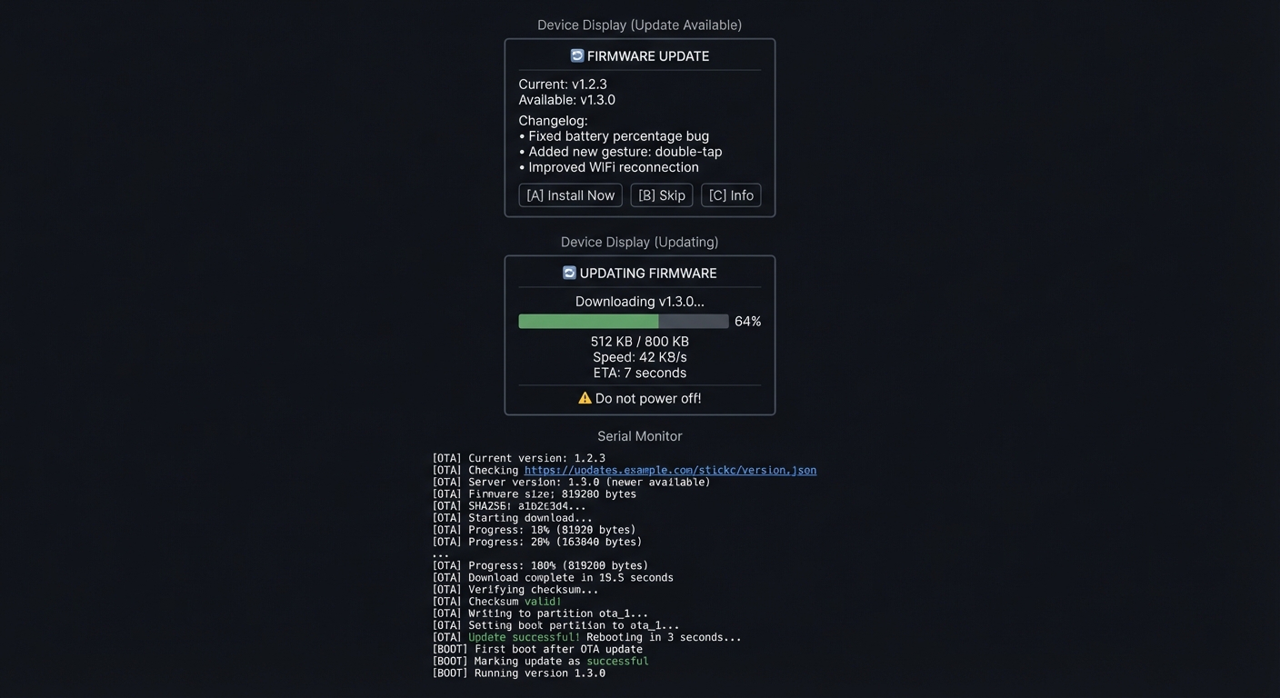
The Core Question You’re Answering
“How do deployed IoT devices safely update themselves without bricking, and how do you ensure only authorized firmware can run?”
Before you write any code, sit with this question. A failed update could brick thousands of devices in the field. A compromised update could turn your devices into a botnet. Production OTA systems need atomicity (all-or-nothing updates), verification (only valid firmware runs), and recovery (ability to rollback failed updates).
Concepts You Must Understand First
Stop and research these before coding:
- ESP32 Partition Table
- What is a partition and how is flash divided?
- What is the difference between ota_0 and ota_1 partitions?
- Where is the bootloader and why can’t you update it via OTA?
- Reference: ESP-IDF Partition Tables documentation
- A/B Update Pattern
- Why do you need two app partitions for safe updates?
- How does the bootloader decide which partition to boot?
- What happens if the new firmware crashes immediately?
- Book Reference: “Making Embedded Systems” Ch. 11 - Elecia White
- Update Verification
- Why is a checksum (SHA256) important?
- What additional protection does code signing provide?
- How does ESP32 Secure Boot work?
- Reference: ESP32 Secure Boot documentation
Questions to Guide Your Design
Before implementing, think through these:
- Version Management
- How will you embed version numbers in firmware?
- Where will you store version metadata on the server?
- How do you prevent downgrade attacks?
- Update Reliability
- What if WiFi drops during download?
- What if the new firmware crashes on boot?
- How long should you wait before marking update successful?
- Security Considerations
- Is HTTPS enough, or do you need code signing?
- Where do you store the signing public key?
- How do you update the signing key if compromised?
Thinking Exercise
Trace an OTA Update
Map the complete update process:
[User triggers update]
        │
        ▼
[1. Check current version]
        │ (read from firmware or NVS)
        ▼
[2. Fetch version.json from server]
        │ (HTTPS GET)
        ▼
[3. Compare versions]
        │ (is server version > current?)
        ▼
[4. Download firmware binary]
        │ (stream to flash, don't buffer in RAM)
        ▼
[5. Verify checksum]
        │ (SHA256 match?)
        ▼
[6. Set next boot partition]
        │ (tell bootloader to try new partition)
        ▼
[7. Reboot]
        │
        ▼
[8. New firmware boots]
        │
        ▼
[9. Mark as successful]
        │ (after N seconds of stable operation)
        ▼
[Done - or rollback if step 8/9 fail]
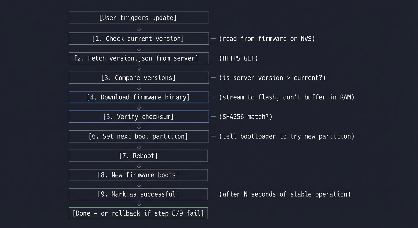
Questions while tracing:
- At which step can you safely abort?
- What happens if power fails during step 4?
- What happens if new firmware has a bug and crashes in step 8?
- How does the bootloader know to fall back to old partition?
The Interview Questions They’ll Ask
Prepare to answer these:
- “Explain the A/B partition scheme and why it’s used for OTA updates.”
- “How would you implement rollback if a firmware update fails?”
- “What security measures would you implement for firmware updates?”
- “How would you handle partial downloads during OTA updates?”
- “Design a system to update 10,000 devices in the field safely.”
Hints in Layers
Hint 1: Use ESP32 OTA APIs
The ESP-IDF provides esp_ota_begin(), esp_ota_write(), and esp_ota_end(). Arduino wraps these in Update.begin() and Update.write().
Hint 2: Stream, Don’t Buffer Firmware is large (500KB-2MB). Don’t try to download it all to RAM. Stream chunks from HTTPS directly to flash.
Hint 3: Implement Health Check
After booting new firmware, wait 30 seconds of stable operation before calling esp_ota_mark_app_valid_cancel_rollback(). If the device crashes before this, bootloader will revert.
Hint 4: Version in Firmware Embed version in your code:
const char* FIRMWARE_VERSION = "1.3.0";
Compare with server’s version.json to decide if update is needed.
Common Pitfalls & Debugging
Problem: “OTA update fails and reboots”
- Why: Partition table mismatch or bad URL
- Fix: Align partition layout and validate URL
- Quick test: Check logs for HTTP and verification errors
Problem: “Device bricks after update”
- Why: No rollback on boot failure
- Fix: Enable OTA rollback and health checks
- Quick test: Force a bad firmware and confirm rollback
Definition of Done
- Update downloads and installs successfully
- Versioning and rollback logic verified
- Progress shown on screen
- Update integrity is validated
Books That Will Help
| Topic | Book | Chapter |
|---|---|---|
| Update strategies | “Making Embedded Systems” by Elecia White | Ch. 11 |
| Flash memory | ESP32 Technical Reference Manual | Ch. 4 |
| Security | ESP32 Security documentation | All |
| Network programming | “TCP/IP Sockets in C” by Donahoo | Ch. 5 |
Implementation Hints
The key insight is that OTA updates must be atomic—either the entire update succeeds, or the system remains on the old firmware. The ESP32’s partition scheme makes this possible.
Partition layout for OTA:
nvs        : 0x009000 (20KB) - settings
otadata    : 0x00e000 (8KB)  - which partition to boot
ota_0      : 0x010000 (1.5MB) - app slot 1
ota_1      : 0x190000 (1.5MB) - app slot 2
The bootloader reads otadata to decide which partition to boot. After successful OTA write, you set the next boot partition, reboot, and the new code runs from the other slot.
For server setup, create:
version.json- metadata about latest versionfirmware.bin- the actual binaryfirmware.sha256- checksum for verification
Simple version.json format:
{
  "version": "1.3.0",
  "url": "https://example.com/firmware.bin",
  "sha256": "a1b2c3d4...",
  "size": 819200,
  "notes": "Bug fixes and improvements"
}
Learning milestones:
- Device checks version.json and reports update available → You understand version management
- Firmware downloads and installs successfully → You understand partition writes
- Failed update triggers automatic rollback → You understand safe update patterns
Project 9: Web-Based Configuration Portal (Captive Portal)
- File: LEARN_M5STACK_STICKC_PLUS2_DEEP_DIVE.md
- Main Programming Language: C++ (Arduino)
- Alternative Programming Languages: ESP-IDF (C), MicroPython
- Coolness Level: Level 3: Genuinely Clever
- Business Potential: 3. The “Service & Support” Model
- Difficulty: Level 2: Intermediate
- Knowledge Area: Web Servers, WiFi AP Mode, HTML/CSS
- Software or Tool: ESPAsyncWebServer, SPIFFS, DNS server
- Main Book: “Learning Web Design” by Robbins (for web fundamentals)
What you’ll build: A WiFi configuration system that creates its own access point, runs a captive portal for initial setup, stores settings in NVS, and provides a web dashboard for ongoing configuration—the standard pattern for consumer IoT devices.
Why it teaches web and embedded integration: Every consumer IoT device needs initial setup without requiring cables or apps. The captive portal pattern (connect to device’s WiFi, get redirected to setup page) is how smart bulbs, thermostats, and routers work. You’ll learn to serve web pages from an embedded device.
Core challenges you’ll face:
- Running ESP32 as a WiFi access point → maps to AP mode configuration
- Implementing DNS hijacking for captive portal → maps to network protocols
- Serving HTML/CSS from flash → maps to embedded web servers
- Persisting configuration across reboots → maps to NVS storage
Key Concepts:
- WiFi AP Mode: ESP32 WiFi documentation - Espressif
- Captive Portal Detection: RFC 7710 and browser behavior
- Embedded Web Server: ESPAsyncWebServer library documentation
- NVS Storage: Making Embedded Systems Ch. 9 - Elecia White
Difficulty: Intermediate Time estimate: 1 week Prerequisites: Basic HTML/CSS knowledge, Project 2 completed
Real World Outcome
You’ll have a device that:
- On first boot, creates “StickC-Setup” WiFi network
- When connected, automatically opens setup page
- Lets user configure WiFi credentials and settings
- Stores configuration and connects to home network
- Provides ongoing web dashboard at device’s IP
Example Output:
Phone Screen (Captive Portal):
┌──────────────────────────────────────────────┐
│ ≡  StickC Plus2 Setup                   ✕   │
├──────────────────────────────────────────────┤
│                                              │
│  ┌────────────────────────────────────────┐  │
│  │  🏠 Welcome to StickC Plus2           │  │
│  │                                        │  │
│  │  Let's get your device connected!     │  │
│  └────────────────────────────────────────┘  │
│                                              │
│  WiFi Network                                │
│  ┌────────────────────────────────────────┐  │
│  │ MyHomeNetwork                      ▼  │  │
│  └────────────────────────────────────────┘  │
│                                              │
│  Password                                    │
│  ┌────────────────────────────────────────┐  │
│  │ ●●●●●●●●●●●●●                         │  │
│  └────────────────────────────────────────┘  │
│                                              │
│  Device Name                                 │
│  ┌────────────────────────────────────────┐  │
│  │ LivingRoom-Sensor                      │  │
│  └────────────────────────────────────────┘  │
│                                              │
│  ┌────────────────────────────────────────┐  │
│  │           Save & Connect               │  │
│  └────────────────────────────────────────┘  │
│                                              │
└──────────────────────────────────────────────┘

Serial Monitor:
[BOOT] First boot detected (no WiFi credentials)
[AP] Starting Access Point: StickC-XXXX
[AP] IP Address: 192.168.4.1
[DNS] Starting captive portal DNS
[WEB] Starting web server on port 80

[DNS] Query for connectivitycheck.gstatic.com → 192.168.4.1
[WEB] GET /hotspot-detect.html → redirecting to /setup
[WEB] GET /setup → serving setup.html (4.2 KB)
[WEB] GET /style.css → 200 OK (1.8 KB)
[WEB] GET /scan → returning 8 networks

[WEB] POST /configure
  SSID: MyHomeNetwork
  Pass: ********
  Name: LivingRoom-Sensor
[NVS] Saving configuration...
[WIFI] Connecting to MyHomeNetwork...
[WIFI] Connected! IP: 192.168.1.47
[AP] Shutting down access point
[WEB] Dashboard available at http://192.168.1.47/
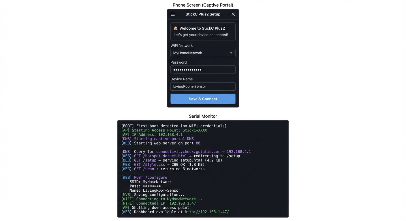
The Core Question You’re Answering
“How do IoT devices get configured for home WiFi without needing a companion app or physical interface?”
Before you write any code, sit with this question. Smart bulbs don’t have screens or keyboards. Yet somehow you can configure them to join your WiFi. The captive portal pattern is the answer: the device creates its own network, you connect to it, and your phone automatically opens a setup webpage—all without installing any app.
Concepts You Must Understand First
Stop and research these before coding:
- WiFi AP vs Station Mode
- What is the difference between AP and STA modes?
- Can ESP32 run both simultaneously (AP+STA)?
- What IP range does the AP use by default?
- Reference: ESP32 WiFi documentation
- Captive Portal Detection
- How does your phone know a WiFi network has a captive portal?
- What URLs do different OS’s check (Android, iOS, Windows)?
- What response triggers the “sign in to network” popup?
- Reference: RFC 7710 and browser captive portal behavior
- DNS Hijacking
- How can the ESP32 intercept all DNS queries?
- Why return your own IP for every domain?
- Is this safe/legal in this context?
- Reference: DNS server library documentation
Questions to Guide Your Design
Before implementing, think through these:
- Setup Flow
- How do you detect first boot vs configured device?
- Should setup be triggered by button press or automatic?
- How do you scan for available networks?
- User Experience
- What if the user enters wrong WiFi password?
- How do you show connection success/failure?
- Should you fall back to AP mode if WiFi connection fails later?
- Security
- Should the setup network be password protected?
- How do you validate input to prevent injection?
- Should the dashboard require authentication?
Thinking Exercise
Map the HTTP Request Flow
When a phone connects to your captive portal:
Phone connects to "StickC-Setup" WiFi
        │
        ▼
Phone makes HTTP request to detect captive portal
  (Android: connectivitycheck.gstatic.com)
  (iOS: captive.apple.com)
        │
        ▼
ESP32 DNS server returns its own IP (192.168.4.1)
        │
        ▼
Phone requests http://connectivitycheck.gstatic.com/generate_204
  (Actually goes to 192.168.4.1!)
        │
        ▼
ESP32 returns 302 redirect to /setup
        │
        ▼
Phone opens built-in browser showing /setup page
        │
        ▼
User fills form and submits
        │
        ▼
ESP32 saves config and connects to real WiFi
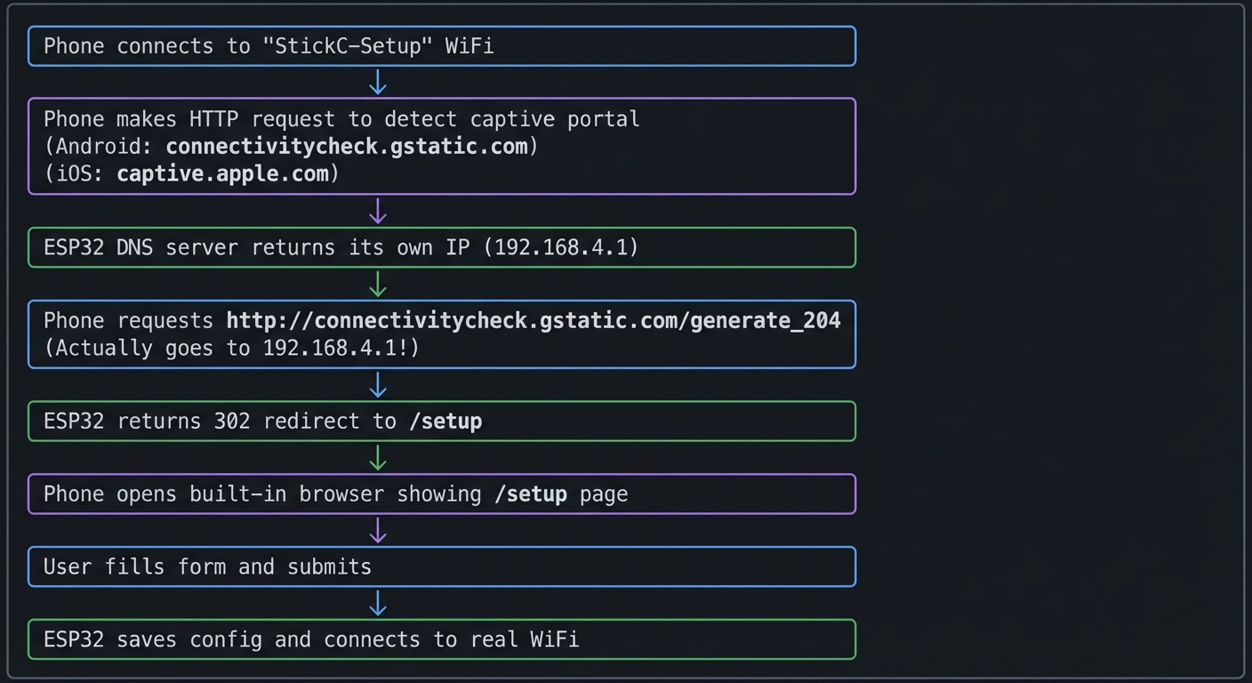
Questions while mapping:
- Why does Android expect a 204 response from connectivity check?
- What happens if you return 200 with content instead of 302 redirect?
- Why do we need a DNS server and not just a web server?
The Interview Questions They’ll Ask
Prepare to answer these:
- “Explain how captive portal detection works on mobile devices.”
- “What is the difference between WiFi AP and station modes?”
- “How would you securely store WiFi credentials on an embedded device?”
- “Describe the process of serving web pages from an embedded system.”
- “How would you implement a fallback mode if the configured WiFi is unavailable?”
Hints in Layers
Hint 1: Start with AP Mode
Use WiFi.softAP("StickC-Setup") to create the access point. Connect from your phone and verify you can reach 192.168.4.1.
Hint 2: Add DNS Server Install DNSServer library. Start it redirecting all queries to your IP:
dnsServer.start(53, "*", WiFi.softAPIP());
Call dnsServer.processNextRequest() in loop().
Hint 3: Serve HTML from SPIFFS
Store your HTML/CSS in the data folder. Use SPIFFS.begin() and serve files with the web server. Or embed HTML as strings in code for simplicity.
Hint 4: Handle All Portal Detection URLs
Respond to /generate_204, /hotspot-detect.html, /ncsi.txt, etc. with redirects to your setup page.
Common Pitfalls & Debugging
Problem: “Captive portal doesn’t open”
- Why: DNS redirect not configured
- Fix: Run a local DNS responder for all domains
- Quick test: Ping a random URL and confirm redirect
Problem: “Config not saved after reboot”
- Why: NVS not committed
- Fix: Commit NVS after write and validate
- Quick test: Reboot and verify settings persist
Definition of Done
- Captive portal loads on first connect
- Settings persist across reboot
- Device reconnects using saved credentials
- Fallback AP mode works
Books That Will Help
| Topic | Book | Chapter |
|---|---|---|
| WiFi programming | ESP32 WiFi documentation | AP/STA modes |
| Web fundamentals | “Learning Web Design” by Robbins | Ch. 1-5 |
| NVS storage | “Making Embedded Systems” by Elecia White | Ch. 9 |
| HTML/forms | MDN Web Docs | Forms guide |
Implementation Hints
The key insight is that captive portals work by hijacking DNS—all domain lookups return the ESP32’s IP, so any HTTP request goes to your server.
Captive portal detection URLs to handle:
- Android:
/generate_204- expect 204, giving anything else triggers portal - iOS:
/hotspot-detect.html- expect specific text, otherwise triggers portal - Windows:
/ncsi.txt- similar pattern
Web server structure:
/           → redirect to /setup
/setup      → serve setup HTML form
/configure  → POST handler for form data
/scan       → JSON list of available networks
/dashboard  → status page (after configuration)
/style.css  → stylesheet
/api/status → JSON device status
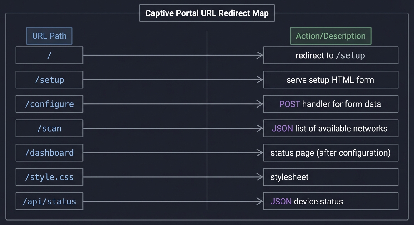
For NVS storage:
preferences.begin("config", false);
preferences.putString("ssid", ssid);
preferences.putString("password", password);
preferences.end();
Check at boot: if NVS has valid credentials, connect to WiFi; otherwise, start AP mode.
Learning milestones:
- Phone auto-opens setup page when connecting to device AP → You understand captive portals
- User can enter WiFi credentials and device connects → You understand the full flow
- Dashboard works after connecting to home network → You’ve built a complete configuration system
Project 10: HAT Module Interface Library (I2C/GPIO Expansion)
- File: LEARN_M5STACK_STICKC_PLUS2_DEEP_DIVE.md
- Main Programming Language: C++ (Arduino)
- Alternative Programming Languages: MicroPython, Rust (ESP-RS)
- Coolness Level: Level 3: Genuinely Clever
- Business Potential: 2. The “Micro-SaaS / Pro Tool”
- Difficulty: Level 3: Advanced
- Knowledge Area: I2C Protocol / Hardware Abstraction
- Software or Tool: HAT modules (ENV III, PIR, ToF, etc.)
- Main Book: “Making Embedded Systems” by Elecia White
What you’ll build: A unified hardware abstraction library that auto-detects and interfaces with various M5Stack HAT modules, providing a consistent API regardless of the underlying sensor type—similar to how operating systems provide device drivers.
Why it teaches M5Stack Plus2: The Plus2’s true power comes from its expansion ecosystem. This project forces you to understand I2C bus scanning, device identification, register mapping, and hardware abstraction—the core skills for any embedded developer working with sensor networks.
Core challenges you’ll face:
- I2C bus scanning and device detection → maps to understanding I2C addressing and ACK/NACK
- Reading device ID registers → maps to understanding sensor register maps
- Creating polymorphic sensor interfaces → maps to hardware abstraction design patterns
- Handling hot-plug detection → maps to interrupt-driven I2C events
Key Concepts:
- I2C Protocol: “Making Embedded Systems” Ch. 7 - Elecia White
- Hardware Abstraction: “Design Patterns” by Gang of Four - Adapter Pattern
- Sensor Datasheets: SHT30, VL53L0X, BH1750 manufacturer documentation
- Device Trees: Linux kernel documentation on device enumeration
Difficulty: Advanced Time estimate: 1-2 weeks Prerequisites: C++ classes and inheritance, I2C communication basics, understanding of sensor registers, completion of at least 2 earlier projects
Real World Outcome
You’ll have a library that works like this:
$ ./hat_manager

HAT Module Manager v1.0
Scanning I2C bus...

[DETECTED] Address 0x44: SHT30 Temperature/Humidity Sensor
  - Temperature: 24.5°C
  - Humidity: 45.2%

[DETECTED] Address 0x29: VL53L0X Time-of-Flight Distance Sensor
  - Distance: 127mm
  - Signal rate: 2.4 Mcps

[DETECTED] Address 0x23: BH1750 Light Sensor
  - Illuminance: 342 lux

[DETECTED] Address 0x68: MPU6886 (built-in IMU)
  - Already managed by system

Total HATs detected: 3
Polling all sensors every 1000ms...

[2024-12-29 10:15:01]
  ENV III: 24.6°C, 45.1% RH
  ToF: 125mm
  Light: 345 lux

[2024-12-29 10:15:02]
  ENV III: 24.6°C, 45.0% RH
  ToF: 131mm (object moved)
  Light: 340 lux
Using your library programmatically:
HATManager manager;
manager.scan();

for (auto& sensor : manager.getSensors()) {
    Serial.printf("%s at 0x%02X\n", sensor->getName(), sensor->getAddress());

    if (sensor->hasCapability(Capability::TEMPERATURE)) {
        auto temp = static_cast<TemperatureSensor*>(sensor);
        Serial.printf("  Temp: %.1f°C\n", temp->readTemperature());
    }
}
The Core Question You’re Answering
“How do operating systems and embedded frameworks discover and communicate with arbitrary hardware devices without knowing in advance what’s connected?”
This is the fundamental question behind plug-and-play, device drivers, and hardware abstraction layers. When you plug a USB device into your computer, it “just works”—but someone had to write the code that scans the bus, reads the device descriptor, loads the appropriate driver, and exposes a uniform API.
Concepts You Must Understand First
Stop and research these before coding:
- I2C Protocol Fundamentals
- What’s the difference between SDA and SCL? Which is data, which is clock?
- Why does I2C use 7-bit addresses but we often see 8-bit values in code?
- What happens during a bus scan? How does ACK/NACK tell you a device exists?
- What’s the maximum number of devices on a single I2C bus?
- Book Reference: “Making Embedded Systems” Ch. 7
- Sensor Register Maps
- How do you read a specific register from an I2C device?
- What’s the difference between a WHO_AM_I register and data registers?
- Why do some sensors require you to write a command before reading?
- Book Reference: Sensor datasheets (SHT30, VL53L0X)
- C++ Polymorphism
- What’s the difference between composition and inheritance?
- When would you use a virtual base class vs. templates?
- What’s the cost of virtual function calls in embedded systems?
- Book Reference: “Design Patterns” by Gang of Four - Adapter Pattern
Questions to Guide Your Design
Before implementing, think through these:
- Device Discovery
- How will you distinguish between a SHT30 and a BH1750 if both respond at similar addresses?
- What if two different HATs have the same I2C address?
- Should detection happen once at startup or continuously?
- API Design
- Should all sensors implement the same interface, or should different sensor types have different methods?
- How will you handle sensors that measure multiple things (temp + humidity)?
- What happens when a HAT is disconnected mid-operation?
- Resource Management
- Should each sensor object own its I2C bus reference, or share one?
- How do you prevent two parts of your code from talking to the same sensor simultaneously?
Thinking Exercise
Trace an I2C Transaction
Before coding, trace what happens when you read temperature from a SHT30:
Master (ESP32)                    Slave (SHT30 @ 0x44)
      |                                   |
      |--[START]------------------------->|
      |--[0x44 << 1 | W = 0x88]---------->|
      |<-[ACK]----------------------------|
      |--[0x2C]-------------------------->| (command MSB)
      |<-[ACK]----------------------------|
      |--[0x06]-------------------------->| (command LSB)
      |<-[ACK]----------------------------|
      |--[STOP]-------------------------->|
      |                                   |
      | (wait 15ms for measurement)       |
      |                                   |
      |--[START]------------------------->|
      |--[0x44 << 1 | R = 0x89]---------->|
      |<-[ACK]----------------------------|
      |<-[temp MSB]-----------------------|
      |--[ACK]--------------------------->|
      |<-[temp LSB]-----------------------|
      |--[ACK]--------------------------->|
      |<-[CRC]-----------------------------|
      |--[NACK]-------------------------->| (signal end)
      |--[STOP]-------------------------->|
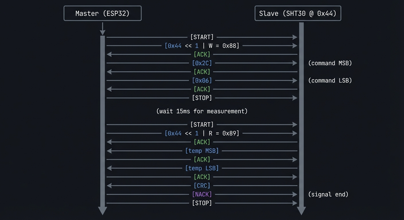
Questions while tracing:
- Why is the address shifted left and OR’d with read/write bit?
- Why does master send NACK before the final STOP?
- What would happen if the sensor wasn’t ready when we tried to read?
The Interview Questions They’ll Ask
- “Explain the I2C protocol. What are the roles of master and slave?”
- “How would you handle address conflicts on an I2C bus?”
- “What’s the difference between hardware abstraction and direct register access? When would you choose each?”
- “How do you detect if an I2C device has disconnected?”
- “Design a sensor fusion system that combines data from multiple sensors. How would you handle different sampling rates?”
Hints in Layers
Hint 1: Start with Bus Scanning
Use Wire.beginTransmission(addr) and Wire.endTransmission() for each address 0x01-0x7F. Return value 0 means device present.
Hint 2: Build a Device Registry Create a table mapping I2C addresses to potential device types. Some addresses are unique (VL53L0X = 0x29), others need ID register reads.
Hint 3: Use Factory Pattern
Create a SensorFactory that takes an I2C address and returns the appropriate sensor object based on device identification.
Hint 4: Handle Polymorphism
Define a base Sensor class with virtual methods like read(), getName(). Derived classes implement sensor-specific logic. Use std::vector<Sensor*> to store all detected sensors.
Common Pitfalls & Debugging
Problem: “External module not detected”
- Why: I2C address collision or wrong pins
- Fix: Scan bus and verify SDA/SCL pins
- Quick test: Run an I2C scanner and confirm address
Problem: “GPIO conflicts with internal peripherals”
- Why: Pin shared with display/buttons
- Fix: Use documented free GPIOs and remap
- Quick test: Toggle pin while display is active and verify no glitches
Definition of Done
- Library detects module and initializes bus
- At least two modules supported end-to-end
- API docs and example sketches included
- Bus errors handled gracefully
Books That Will Help
| Topic | Book | Chapter |
|---|---|---|
| I2C protocol | “Making Embedded Systems” by Elecia White | Ch. 7 |
| Hardware abstraction | “Design Patterns” by Gang of Four | Adapter Pattern |
| C++ embedded patterns | “Real-Time C++” by Kormanyos | Ch. 6-7 |
| Sensor interfacing | Manufacturer datasheets | Register maps |
Implementation Hints
The key insight is that I2C devices identify themselves through registers. Most sensors have a “WHO_AM_I” or device ID register that returns a known value.
Device identification strategy:
1. Scan bus for responding addresses
2. For each address, attempt to read ID register
3. Match ID against known device database
4. Instantiate appropriate driver class
Common HAT sensors and their identification:
Address  | Device       | ID Register | ID Value
---------|--------------|-------------|----------
0x44     | SHT30        | N/A         | Use address
0x29     | VL53L0X      | 0xC0        | 0xEE
0x23/0x5C| BH1750       | N/A         | Use address
0x38     | AHT20        | N/A         | Use address
0x76/0x77| BMP280       | 0xD0        | 0x58
Polymorphic sensor base class approach:
class Sensor {
public:
    virtual ~Sensor() = default;
    virtual const char* getName() = 0;
    virtual uint8_t getAddress() = 0;
    virtual void update() = 0;
    virtual bool hasCapability(Capability cap) = 0;
};

class TemperatureSensor : public Sensor {
public:
    virtual float readTemperature() = 0;
};

class SHT30 : public TemperatureSensor {
    // Implementation
};
Learning milestones:
- Bus scan finds all connected HATs → You understand I2C addressing
- Devices are correctly identified and instantiated → You understand device enumeration
- Unified API reads all sensors regardless of type → You’ve built a hardware abstraction layer
Project 11: Multi-Protocol Gateway (BLE + WiFi + IR Bridge)
- File: LEARN_M5STACK_STICKC_PLUS2_DEEP_DIVE.md
- Main Programming Language: C++ (Arduino)
- Alternative Programming Languages: MicroPython, ESP-IDF
- Coolness Level: Level 4: Hardcore Tech Flex
- Business Potential: 3. The “Service & Support” Model
- Difficulty: Level 4: Expert
- Knowledge Area: Protocol Bridging / IoT Gateway
- Software or Tool: BLE, WiFi, IR, MQTT
- Main Book: “Computer Networks” by Tanenbaum
What you’ll build: A universal IoT gateway that bridges BLE devices (like fitness trackers), WiFi/MQTT cloud services, and IR-controlled appliances—all through a single StickC Plus2. Send a BLE notification to turn on your TV, or control BLE lights from a cloud dashboard.
Why it teaches M5Stack Plus2: This project exercises ALL the Plus2’s communication capabilities simultaneously: WiFi, BLE, and IR. You’ll learn how to manage multiple concurrent protocols, handle protocol translation, and build a true edge computing device.
Core challenges you’ll face:
- Running BLE and WiFi concurrently → maps to ESP32 dual-mode radio management
- Protocol translation logic → maps to message routing and transformation
- Managing connection state across protocols → maps to state machine design
- IR code learning and replay → maps to timing-critical signal generation
Key Concepts:
- Protocol Bridging: “Computer Networks” Ch. 5-6 - Tanenbaum
- BLE GATT: “Getting Started with Bluetooth Low Energy” by Townsend
- State Machines: “Making Embedded Systems” Ch. 5 - Elecia White
- Message Queues: “Real-Time Concepts for Embedded Systems” Ch. 8
Difficulty: Expert Time estimate: 2-3 weeks Prerequisites: Completion of Projects 3, 5, 9; understanding of BLE GATT, MQTT, and IR protocols; comfort with concurrent programming
Real World Outcome
Your gateway provides a unified control interface:
$ mosquitto_pub -t "gateway/cmd" -m '{"action":"ir_send","device":"tv","command":"power"}'

Gateway response (on MQTT topic gateway/status):
{
  "status": "success",
  "action": "ir_send",
  "device": "tv",
  "command": "power",
  "timestamp": "2024-12-29T10:30:00Z"
}

# Your TV turns on!
BLE notification triggers MQTT:
[BLE] Received notification from Mi Band 6:
  Heart rate: 85 BPM

[MQTT] Publishing to health/heartrate:
  {"device":"miband6","hr":85,"timestamp":"2024-12-29T10:30:15Z"}
Cloud command controls BLE device:
$ mosquitto_pub -t "gateway/cmd" -m '{"action":"ble_write","device":"led_strip","char":"color","value":"FF0000"}'

[Gateway] Writing to BLE device led_strip
[Gateway] Characteristic 0xFFE1 written: FF0000
[Result] LED strip turns red!
The display shows:
┌──────────────────────────┐
│  Protocol Gateway v1.0   │
├──────────────────────────┤
│ WiFi: Connected ✓        │
│ MQTT: broker.local ✓     │
│ BLE:  3 devices paired   │
│                          │
│ Last actions:            │
│ → IR: TV power           │
│ ← BLE: HR 85 bpm         │
│ → BLE: LED red           │
└──────────────────────────┘
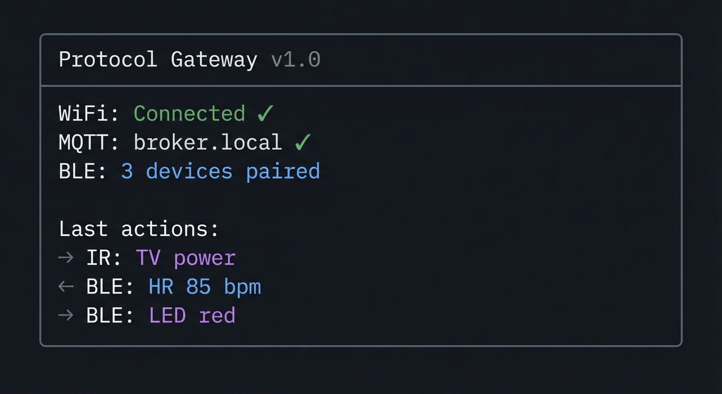
The Core Question You’re Answering
“How do IoT gateways translate between incompatible protocols to create unified smart home/building systems?”
This is the core challenge of IoT integration. Your Philips Hue uses Zigbee, your TV uses IR, your fitness tracker uses BLE, and your cloud uses MQTT/HTTP. The gateway is the translator that makes them all work together.
Concepts You Must Understand First
Stop and research these before coding:
- ESP32 Radio Coexistence
- Can ESP32 use WiFi and BLE simultaneously?
- What’s the performance impact of running both radios?
- How does time-slicing work for shared radio resources?
- Book Reference: ESP-IDF documentation on coexistence
- Protocol Translation Patterns
- What’s the difference between a gateway, bridge, and proxy?
- How do you map concepts between different protocols (BLE characteristics → MQTT topics)?
- What are the latency implications of protocol bridging?
- Book Reference: “Computer Networks” Ch. 5
- Message Routing
- How do you decide which output protocol handles an input message?
- What’s a message broker and how does it differ from a gateway?
- How do you handle messages that need responses?
- Book Reference: “Enterprise Integration Patterns” by Hohpe
Questions to Guide Your Design
Before implementing, think through these:
- Message Format
- What’s your canonical internal message format?
- How do you represent IR commands vs. BLE characteristics vs. MQTT messages?
- Should translation happen at the edge or just forwarding?
- Device Management
- How do you track which BLE devices are paired?
- How do you store learned IR codes?
- What happens when a device disconnects?
- Concurrency
- How do you handle an IR command arriving while a BLE scan is in progress?
- Should each protocol have its own FreeRTOS task?
- How do you avoid race conditions in shared state?
Thinking Exercise
Design the Message Flow
Before coding, diagram how a cloud command flows through your system:
MQTT Message Arrives
        │
        ▼
┌───────────────────┐
│ Parse JSON        │
│ {"action":"ir",   │
│  "device":"tv",   │
│  "cmd":"power"}   │
└───────┬───────────┘
        │
        ▼
┌───────────────────┐
│ Route to Handler  │
│ action == "ir"    │
│ → IR Handler      │
└───────┬───────────┘
        │
        ▼
┌───────────────────┐
│ Lookup IR Code    │
│ device:"tv"       │
│ cmd:"power"       │
│ → NEC: 0x20DF10EF │
└───────┬───────────┘
        │
        ▼
┌───────────────────┐
│ Transmit IR       │
│ 38kHz carrier     │
│ NEC protocol      │
└───────┬───────────┘
        │
        ▼
┌───────────────────┐
│ Publish Result    │
│ gateway/status    │
│ {"status":"ok"}   │
└───────────────────┘
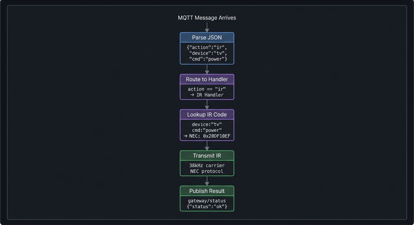
Questions while diagramming:
- What if the device name doesn’t exist in your IR code database?
- How long should the gateway wait before reporting timeout?
- Should the response be synchronous or asynchronous?
The Interview Questions They’ll Ask
- “Design an IoT gateway that bridges Zigbee, WiFi, and Bluetooth devices. What are the key challenges?”
- “How would you handle protocol translation with different data models?”
- “What’s the difference between synchronous and asynchronous message passing? When would you use each?”
- “How do you ensure reliability in a system bridging unreliable protocols?”
- “Design a state machine for managing BLE connections with automatic reconnection.”
Hints in Layers
Hint 1: Use FreeRTOS Tasks Create separate tasks for WiFi/MQTT, BLE, and IR. Use queues to pass messages between them. This prevents one slow protocol from blocking others.
Hint 2: Define a Common Message Format
Create a GatewayMessage struct with fields for source protocol, destination protocol, device ID, action, and payload. All handlers convert to/from this format.
Hint 3: Build Protocol Handlers as Plugins
Each protocol (BLE, IR, MQTT) is a handler class with send() and receive() methods. A router dispatches messages to the appropriate handler.
Hint 4: Persist Device Mappings Store BLE device addresses, IR codes, and MQTT topic mappings in NVS. Provide a REST API or serial interface to configure them.
Common Pitfalls & Debugging
Problem: “Gateway latency is too high”
- Why: Blocking calls in shared task
- Fix: Separate protocols into tasks with queues
- Quick test: Measure end-to-end latency with timestamps
Problem: “Message storms crash device”
- Why: No rate limiting or backpressure
- Fix: Add queue bounds and drop policy
- Quick test: Simulate burst traffic and observe stability
Definition of Done
- BLE/WiFi/IR bridge works end-to-end
- Queueing prevents protocol contention
- Throughput and latency measured
- Status UI shows link health
Books That Will Help
| Topic | Book | Chapter |
|---|---|---|
| Protocol bridging | “Computer Networks” by Tanenbaum | Ch. 5-6 |
| BLE programming | “Getting Started with Bluetooth Low Energy” by Townsend | Ch. 4-6 |
| Message patterns | “Enterprise Integration Patterns” by Hohpe | Ch. 3-4 |
| FreeRTOS tasks | “Mastering the FreeRTOS Kernel” by Barry | Ch. 3-4 |
Implementation Hints
The key architectural insight is separation of concerns: each protocol handler knows only its own protocol. The router knows how to dispatch messages between handlers.
System architecture:
                    ┌─────────────────┐
                    │   Message Bus   │
                    │  (FreeRTOS Q)   │
                    └───────┬─────────┘
           ┌────────────────┼────────────────┐
           ▼                ▼                ▼
   ┌───────────────┐ ┌───────────────┐ ┌───────────────┐
   │ MQTT Handler  │ │  BLE Handler  │ │  IR Handler   │
   │               │ │               │ │               │
   │ - Subscribe   │ │ - Scan        │ │ - Learn       │
   │ - Publish     │ │ - Connect     │ │ - Transmit    │
   │ - Parse JSON  │ │ - Read/Write  │ │ - Decode      │
   └───────────────┘ └───────────────┘ └───────────────┘
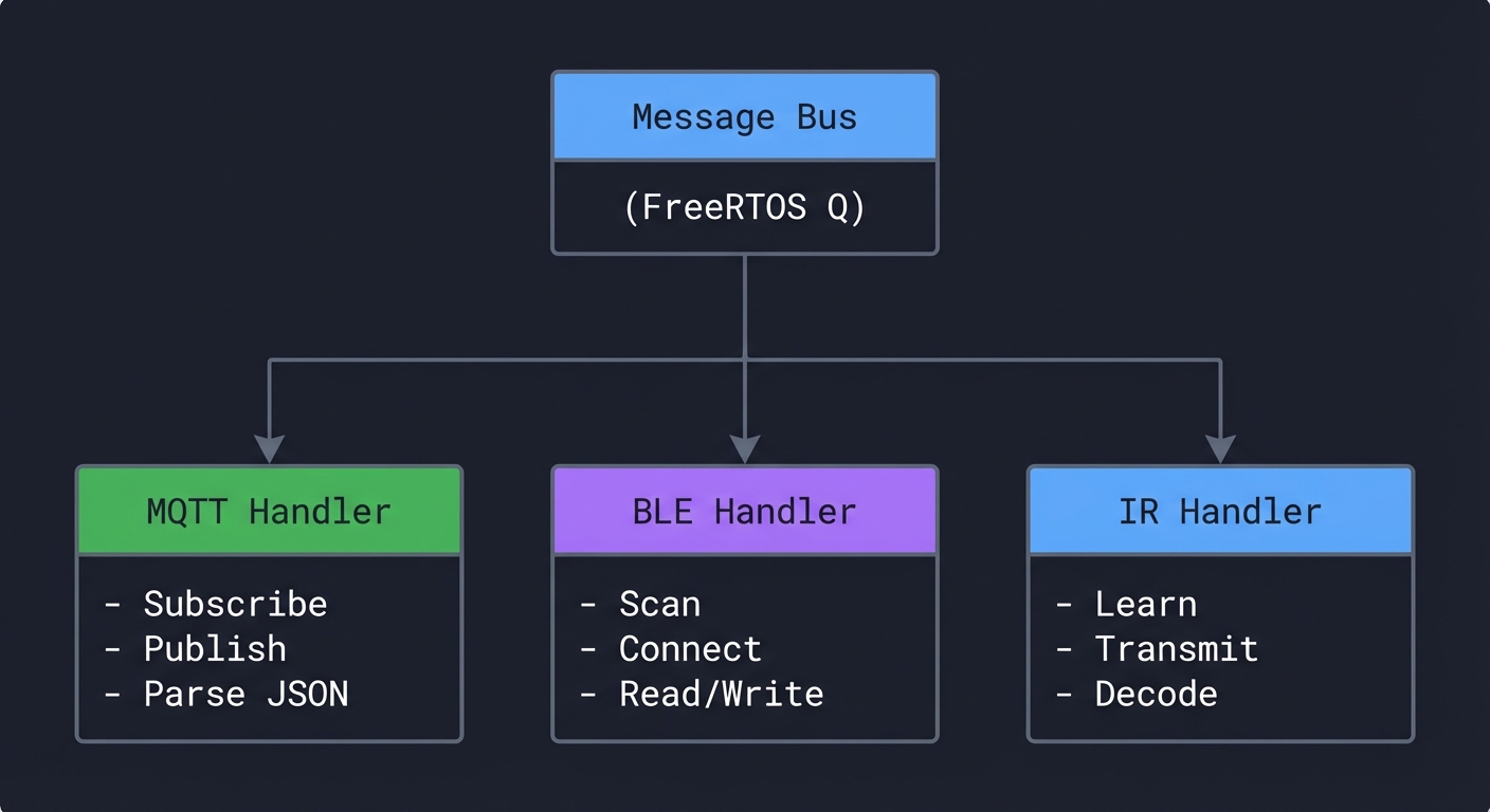
FreeRTOS task structure:
// Message queue
QueueHandle_t messageQueue = xQueueCreate(10, sizeof(GatewayMessage));

// MQTT task - runs on Core 0
void mqttTask(void* param) {
    while(true) {
        // Check for MQTT messages
        // Convert to GatewayMessage
        // Send to queue
        vTaskDelay(10);
    }
}

// BLE task - runs on Core 1
void bleTask(void* param) {
    while(true) {
        // Check for messages from queue destined for BLE
        // Handle BLE events
        vTaskDelay(10);
    }
}
Protocol translation example:
// MQTT message: {"action":"ble","device":"led","char":"color","value":"FF0000"}
// Translates to:
// - Find BLE device with name "led"
// - Find characteristic with name "color"
// - Write value bytes [0xFF, 0x00, 0x00]
Learning milestones:
- All three protocols work independently → You understand each protocol
- Messages route correctly between protocols → You understand message passing
- Full integration: cloud command controls BLE device via gateway → You’ve built a real IoT edge device
Project 12: Wireless Sensor Mesh Network (ESP-NOW + Display Dashboard)
- File: LEARN_M5STACK_STICKC_PLUS2_DEEP_DIVE.md
- Main Programming Language: C++ (Arduino)
- Alternative Programming Languages: ESP-IDF, MicroPython
- Coolness Level: Level 4: Hardcore Tech Flex
- Business Potential: 3. The “Service & Support” Model
- Difficulty: Level 4: Expert
- Knowledge Area: Mesh Networking / Distributed Systems
- Software or Tool: ESP-NOW, Multiple ESP32 devices
- Main Book: “Computer Networks” by Tanenbaum
What you’ll build: A mesh network of multiple StickC Plus2 (or other ESP32) devices that communicate peer-to-peer using ESP-NOW, with one device acting as a dashboard displaying aggregated data from all nodes—creating a wireless sensor network without any WiFi infrastructure.
Why it teaches M5Stack Plus2: ESP-NOW is ESP32’s secret weapon for building infrastructure-free mesh networks. This project teaches you distributed systems concepts, peer-to-peer communication, data aggregation, and how to build systems that work without WiFi or cloud services.
Core challenges you’ll face:
- ESP-NOW peer discovery and pairing → maps to mesh network formation
- Reliable message delivery without TCP → maps to application-level acknowledgment
- Time synchronization across nodes → maps to distributed clock challenges
- Dashboard aggregation and display → maps to data fusion and visualization
Key Concepts:
- Mesh Networking: “Computer Networks” Ch. 5 - Tanenbaum
- Distributed Systems: “Designing Data-Intensive Applications” Ch. 8 - Kleppmann
- ESP-NOW Protocol: ESP-IDF documentation
- Data Aggregation: “Making Embedded Systems” Ch. 11 - Elecia White
Difficulty: Expert Time estimate: 2-3 weeks Prerequisites: Understanding of WiFi basics, experience with multiple ESP32 devices, completion of at least 5 earlier projects
Real World Outcome
With 3+ StickC Plus2 devices, you’ll have:
Node 1 (Kitchen) display:
┌──────────────────────────┐
│ Kitchen Node - ID: 0x01  │
├──────────────────────────┤
│ Local Sensors:           │
│  Temp: 23.5°C            │
│  Humidity: 55%           │
│  Light: 450 lux          │
│                          │
│ Mesh Status: 3 peers     │
│ Last TX: 2s ago          │
│ Signal: -45 dBm          │
└──────────────────────────┘
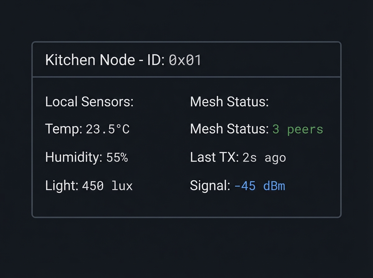
Dashboard Node display:
┌────────────────────────────────────────┐
│     Mesh Network Dashboard             │
├────────────────────────────────────────┤
│ Nodes Online: 3/3           ▲ Healthy  │
├────────────────────────────────────────┤
│ Kitchen (0x01)    23.5°C  55%  -45dBm │
│ Living  (0x02)    24.1°C  52%  -52dBm │
│ Bedroom (0x03)    22.8°C  58%  -61dBm │
├────────────────────────────────────────┤
│ Network Stats:                         │
│ Messages/min: 18    Lost: 0.5%        │
│ Uptime: 4h 23m     Last poll: 1s      │
└────────────────────────────────────────┘
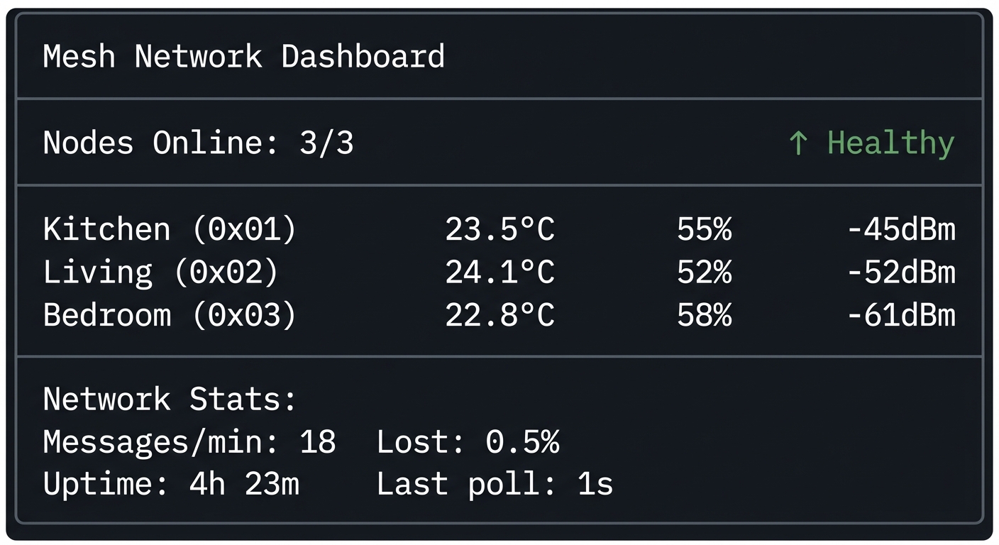
Serial output from dashboard:
[MESH] Received from 0x24:6F:28:AB:CD:EF
  Node ID: 0x01 (Kitchen)
  Temperature: 23.5°C
  Humidity: 55%
  Light: 450 lux
  Battery: 87%
  RSSI: -45 dBm
  Seq: 1234

[MESH] Network status:
  Active peers: 3
  Messages received: 1234
  Messages lost: 6 (0.5%)
  Uptime: 15663 seconds
The Core Question You’re Answering
“How do devices communicate and coordinate without any centralized infrastructure like WiFi routers or cloud servers?”
This is the fundamental challenge of mesh networking, ad-hoc networks, and peer-to-peer systems. Your mesh network has no single point of failure, works in environments without WiFi, and can be the basis for disaster communication systems, agricultural sensors, or building monitoring.
Concepts You Must Understand First
Stop and research these before coding:
- ESP-NOW Protocol
- What layer of the network stack does ESP-NOW operate at?
- What’s the maximum payload size? Maximum range?
- How does peer registration work?
- Can you broadcast to all peers or must you specify addresses?
- Book Reference: ESP-IDF ESP-NOW documentation
- Mesh Network Topologies
- What’s the difference between star, tree, and mesh topologies?
- What are the tradeoffs of each for sensor networks?
- How do packets route in a multi-hop mesh?
- Book Reference: “Computer Networks” Ch. 5
- Reliable Messaging Without TCP
- How do you detect lost messages without TCP acknowledgments?
- What’s the difference between at-most-once, at-least-once, and exactly-once delivery?
- How do you handle duplicate messages?
- Book Reference: “Designing Data-Intensive Applications” Ch. 8
Questions to Guide Your Design
Before implementing, think through these:
- Network Formation
- How do nodes discover each other?
- Should there be a dedicated coordinator node or is it fully peer-to-peer?
- What happens when a new node joins the network?
- Message Design
- What data should each message contain?
- How do you handle messages that are too large for one ESP-NOW packet?
- Should you use binary or text encoding?
- Reliability
- How do you detect if a node goes offline?
- Should sensor nodes retry failed transmissions?
- How do you handle network partitions?
Thinking Exercise
Design the Message Protocol
Before coding, design your mesh message format:
ESP-NOW Message (max 250 bytes)
┌─────────────────────────────────────────┐
│ Header (8 bytes)                        │
├─────────────────────────────────────────┤
│ Magic: 0xESP1  (2 bytes)               │
│ Version: 0x01  (1 byte)                │
│ Type:    0x01  (1 byte)                │
│   0x01 = sensor data                    │
│   0x02 = discovery                      │
│   0x03 = acknowledgment                 │
│   0x04 = time sync                      │
│ Sequence: uint16 (2 bytes)              │
│ Node ID:  uint16 (2 bytes)              │
├─────────────────────────────────────────┤
│ Payload (variable, type-dependent)      │
├─────────────────────────────────────────┤
│ For type 0x01 (sensor data):            │
│   Temperature: int16 (°C × 100)         │
│   Humidity:    uint8 (%)                │
│   Light:       uint16 (lux)             │
│   Battery:     uint8 (%)                │
│   Timestamp:   uint32 (ms since boot)   │
├─────────────────────────────────────────┤
│ CRC16 (2 bytes)                         │
└─────────────────────────────────────────┘
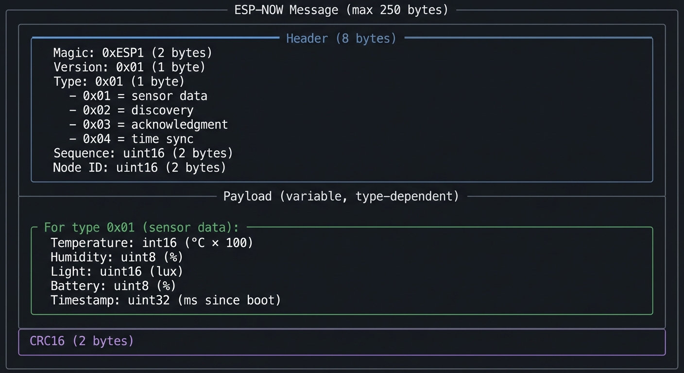
Questions while designing:
- Why use fixed-point instead of float for temperature?
- How will you detect corrupt messages?
- What happens if two nodes have the same Node ID?
The Interview Questions They’ll Ask
- “Design a sensor mesh network for a large warehouse. How would you handle node discovery?”
- “What are the tradeoffs between ESP-NOW, WiFi mesh, and Zigbee for IoT applications?”
- “How would you implement reliable message delivery over an unreliable channel?”
- “What happens when a mesh network partitions? How would you detect and handle it?”
- “How would you synchronize time across nodes without internet access?”
Hints in Layers
Hint 1: Start with Pair of Nodes Get two nodes talking first. Use fixed MAC addresses. Once basic send/receive works, add discovery.
Hint 2: Use Broadcast for Discovery ESP-NOW can send to broadcast MAC (FF:FF:FF:FF:FF:FF). New nodes announce themselves this way. Existing nodes respond with their info.
Hint 3: Implement Sequence Numbers Each node maintains a sequence number that increments with each message. Receivers can detect gaps (lost messages) and duplicates.
Hint 4: Build Dashboard as Aggregator The dashboard node is just another peer, but instead of transmitting sensor data, it listens and aggregates. Display updates when new data arrives from any node.
Common Pitfalls & Debugging
Problem: “Nodes never discover each other”
- Why: ESP-NOW channel mismatch
- Fix: Lock channels or sync via WiFi setup
- Quick test: Log channels and verify alignment
Problem: “Packets drop under load”
- Why: No retry or ack
- Fix: Implement ack + retry with backoff
- Quick test: Send 100 packets and verify delivery rate
Definition of Done
- Mesh nodes discover and display peers
- Messages delivered with retries/acks
- Dashboard shows network status
- Network survives node dropouts
Books That Will Help
| Topic | Book | Chapter |
|---|---|---|
| Mesh networking | “Computer Networks” by Tanenbaum | Ch. 5 |
| Distributed systems | “Designing Data-Intensive Applications” by Kleppmann | Ch. 8 |
| ESP-NOW protocol | ESP-IDF documentation | ESP-NOW guide |
| Wireless sensors | “Making Embedded Systems” by Elecia White | Ch. 11 |
Implementation Hints
The key insight is that ESP-NOW is a connectionless protocol—you send packets to MAC addresses, and they either arrive or they don’t. You must build reliability on top.
ESP-NOW basics:
// Initialize ESP-NOW
WiFi.mode(WIFI_STA);
esp_now_init();

// Register receive callback
esp_now_register_recv_cb(onDataRecv);

// Register send callback
esp_now_register_send_cb(onDataSent);

// Add peer
esp_now_peer_info_t peerInfo;
memcpy(peerInfo.peer_addr, peerMAC, 6);
peerInfo.channel = 0;
peerInfo.encrypt = false;
esp_now_add_peer(&peerInfo);

// Send data
esp_now_send(peerMAC, (uint8_t*)&message, sizeof(message));
Node discovery protocol:
1. New node boots, starts broadcasting discovery every 5s
2. Existing nodes receive broadcast, add new peer
3. Existing nodes send unicast response with their info
4. New node receives responses, builds peer list
5. After 30s with no new peers, stop broadcasting
Dashboard aggregation:
struct NodeData {
    uint8_t mac[6];
    uint16_t nodeId;
    float temperature;
    float humidity;
    uint16_t light;
    uint8_t battery;
    uint32_t lastSeen;
    int8_t rssi;
    uint16_t lastSeq;
};

std::map<uint16_t, NodeData> nodes;

void updateDashboard() {
    M5.Lcd.clear();
    for (auto& [id, node] : nodes) {
        // Draw node info
        // Check if stale (lastSeen > 30s ago)
    }
}
Learning milestones:
- Two nodes exchange messages reliably → You understand ESP-NOW basics
- Network self-forms with discovery protocol → You understand mesh formation
- Dashboard shows all nodes with live updates → You’ve built a distributed sensor system
Final Capstone Project: Smart Home Hub with Voice Feedback and Cloud Integration
- File: LEARN_M5STACK_STICKC_PLUS2_DEEP_DIVE.md
- Main Programming Language: C++ (Arduino/ESP-IDF)
- Alternative Programming Languages: MicroPython, Rust (ESP-RS)
- Coolness Level: Level 5: Pure Magic (Super Cool)
- Business Potential: 4. The “Open Core” Infrastructure
- Difficulty: Level 5: Master
- Knowledge Area: Full-Stack IoT / Edge Computing
- Software or Tool: All Plus2 capabilities combined
- Main Book: “Designing Data-Intensive Applications” by Kleppmann
What you’ll build: A complete smart home hub that integrates everything you’ve learned: reads sensors via I2C HATs, controls devices via IR and BLE, communicates with cloud via MQTT, displays real-time dashboards, manages configuration via web portal, supports OTA updates, uses deep sleep for battery efficiency, and provides audio feedback via the built-in speaker—all while coordinating multiple ESP32 nodes via ESP-NOW mesh.
Why this is the ultimate M5Stack Plus2 project: This capstone combines every hardware and software capability of the Plus2 into a single, cohesive system. Building this proves you’ve mastered embedded systems, networking protocols, user interface design, power management, and distributed systems—the complete toolkit of a professional IoT engineer.
Core challenges you’ll face:
- Resource management with limited RAM → maps to embedded systems constraints
- Coordinating multiple concurrent subsystems → maps to real-time OS design
- Graceful degradation when components fail → maps to fault tolerance
- Seamless user experience across interfaces → maps to product engineering
- Security across multiple attack surfaces → maps to IoT security
Key Concepts:
- System Architecture: “Designing Data-Intensive Applications” Ch. 1-2 - Kleppmann
- FreeRTOS Integration: “Mastering the FreeRTOS Kernel” by Barry
- IoT Security: “Practical IoT Hacking” by Chantzis et al.
- Product Engineering: “Making Embedded Systems” Ch. 12 - Elecia White
Difficulty: Master Time estimate: 1-2 months Prerequisites: Completion of at least 8 previous projects including Projects 10, 11, and 12; strong understanding of all Plus2 subsystems
Real World Outcome
Your smart home hub provides:
Main Dashboard Display:
┌────────────────────────────────────────┐
│ ◉ Smart Home Hub      ☁️ Online  🔋 87% │
├────────────────────────────────────────┤
│ Living Room    24.1°C  52%  💡 ON      │
│ Kitchen        23.5°C  55%  💡 OFF     │
│ Bedroom        22.8°C  58%  💡 ON      │
├────────────────────────────────────────┤
│ Scenes: [Morning] [Away] [Night]       │
│ Last: Motion detected (Kitchen) 2m    │
└────────────────────────────────────────┘
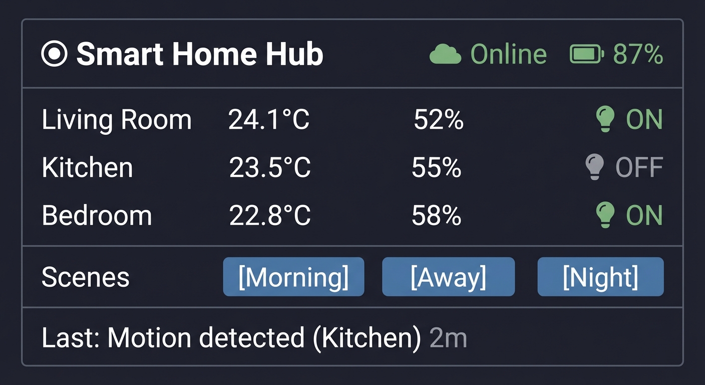
Voice/Audio Feedback:
"Good morning. Living room temperature is 24 degrees.
 Three devices are online. Would you like me to
 activate the morning scene?"
Cloud Dashboard (via MQTT/HTTP API):
{
  "hub_id": "home_001",
  "status": "online",
  "uptime_hours": 168,
  "rooms": [
    {"name": "Living Room", "temp": 24.1, "humidity": 52, "light": "on"},
    {"name": "Kitchen", "temp": 23.5, "humidity": 55, "motion": true},
    {"name": "Bedroom", "temp": 22.8, "humidity": 58, "light": "on"}
  ],
  "mesh_nodes": 3,
  "last_update": "2024-12-29T10:45:00Z"
}
Web Configuration Portal:
┌─────────────────────────────────────────────────┐
│ Smart Home Hub Configuration                    │
├─────────────────────────────────────────────────┤
│ WiFi: [Home_Network_5G    ] [••••••••]         │
│ MQTT Broker: [broker.home.local:1883  ]        │
│ Time Zone: [America/New_York ▼]                │
│                                                 │
│ Scenes:                                         │
│ ┌───────────┬────────────────────────────────┐ │
│ │ Morning   │ Lights 50%, AC 72°F, Radio ON  │ │
│ │ Away      │ Lights OFF, AC 78°F, Alerts ON │ │
│ │ Night     │ Lights 10%, AC 68°F            │ │
│ └───────────┴────────────────────────────────┘ │
│                                                 │
│ [Save] [Reboot] [Factory Reset]                │
└─────────────────────────────────────────────────┘
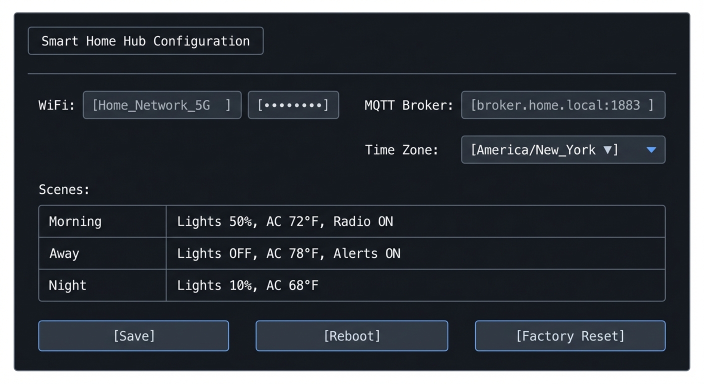
The Core Question You’re Answering
“How do you architect a complex embedded system that integrates multiple protocols, manages limited resources, provides excellent user experience, and remains maintainable and extensible?”
This is the question every professional IoT product engineer faces. The answer involves careful system design, clear separation of concerns, robust error handling, and thoughtful user experience design.
Architecture Overview
                    ┌─────────────────────────────────────────┐
                    │              Cloud Services              │
                    │  (MQTT Broker, REST API, Dashboard)      │
                    └────────────────┬────────────────────────┘
                                     │ WiFi/HTTPS/MQTT
                                     ▼
┌────────────────────────────────────────────────────────────────┐
│                    M5Stack StickC Plus2 Hub                    │
├────────────────────────────────────────────────────────────────┤
│  ┌──────────────┐  ┌──────────────┐  ┌──────────────┐        │
│  │ Display Mgr  │  │   Audio Mgr  │  │  Power Mgr   │        │
│  │ (TFT_eSPI)   │  │  (I2S/Buzz)  │  │ (Deep Sleep) │        │
│  └──────────────┘  └──────────────┘  └──────────────┘        │
│                                                                │
│  ┌──────────────────────────────────────────────────────────┐ │
│  │                     State Machine                        │ │
│  │        (FreeRTOS Tasks + Event Queue + NVS)              │ │
│  └──────────────────────────────────────────────────────────┘ │
│                                                                │
│  ┌──────────────┐  ┌──────────────┐  ┌──────────────┐        │
│  │  WiFi/MQTT   │  │  BLE Handler │  │  IR Handler  │        │
│  │   Handler    │  │  (Devices)   │  │ (Appliances) │        │
│  └──────────────┘  └──────────────┘  └──────────────┘        │
│                                                                │
│  ┌──────────────┐  ┌──────────────┐  ┌──────────────┐        │
│  │  I2C/HAT     │  │   ESP-NOW    │  │    Web       │        │
│  │   Manager    │  │  Mesh Mgr    │  │   Server     │        │
│  └──────────────┘  └──────────────┘  └──────────────┘        │
└────────────────────────────────────────────────────────────────┘
                         │ ESP-NOW                    │ I2C
                         ▼                            ▼
            ┌─────────────────────┐      ┌─────────────────┐
            │   Remote Nodes      │      │   HAT Sensors   │
            │ (Kitchen, Bedroom)  │      │ (ENV, PIR, ToF) │
            └─────────────────────┘      └─────────────────┘
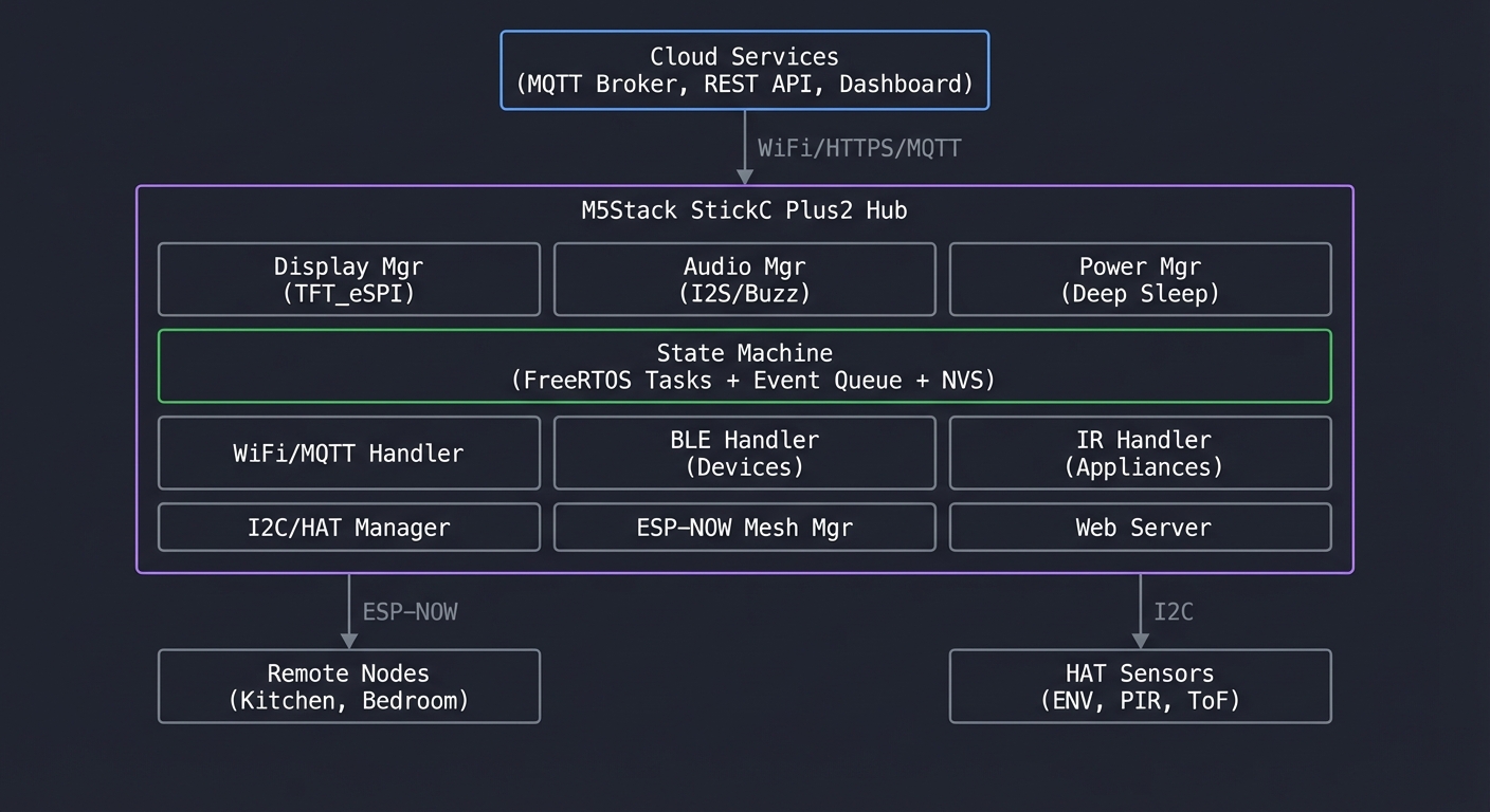
System Components and Integration
1. Core State Machine
- Central event queue processes all inputs
- State persists to NVS for crash recovery
- Scenes = named state presets
2. Communication Layer
- WiFi: Cloud connectivity + web server
- BLE: Control smart devices (lights, locks)
- IR: Legacy device control (TV, AC)
- ESP-NOW: Mesh with sensor nodes
3. Sensor Layer
- Built-in: IMU (gestures), RTC (schedules), mic (future voice)
- HAT modules: ENV (temp/humidity), PIR (motion), ToF (presence)
- Remote: ESP-NOW sensor nodes
4. User Interface
- Display: Real-time dashboard with touch zones
- Audio: Status announcements, alerts
- Web: Configuration portal
- Cloud: MQTT + REST API
5. Power Management
- Battery monitoring with low-power alerts
- Deep sleep during inactivity
- Wake on button/motion/schedule
Implementation Roadmap
Phase 1: Core Framework (Week 1-2)
- Set up FreeRTOS task structure
- Implement event queue
- Create state machine skeleton
- Add NVS persistence
Phase 2: Communication (Week 2-3)
- WiFi manager with auto-reconnect
- MQTT client with QoS handling
- BLE scanner and device manager
- IR code database
Phase 3: Sensors (Week 3-4)
- HAT auto-detection (from Project 10)
- ESP-NOW mesh integration (from Project 12)
- Data fusion and filtering
Phase 4: User Interface (Week 4-5)
- Display dashboard with animations
- Web configuration portal
- Audio feedback system
- Scene management
Phase 5: Integration & Polish (Week 5-6)
- OTA update support
- Security hardening
- Power optimization
- Stress testing
Learning Milestones
- All subsystems work independently → You understand each component
- Event-driven architecture handles cross-system communication → You understand system design
- System recovers gracefully from any failure → You’ve built production-quality software
- Complete user experience from mobile to cloud → You’ve built a real product
Project Comparison Table
| # | Project | Difficulty | Time | Key Concepts | Fun Factor |
|---|---|---|---|---|---|
| 1 | Digital Instrument Cluster | Beginner | Weekend | TFT display, sprites, animation | ⭐⭐⭐⭐ |
| 2 | Environmental Monitor | Intermediate | 1 week | WiFi, MQTT, cloud IoT | ⭐⭐⭐ |
| 3 | Universal IR Remote | Intermediate | 1 week | NEC protocol, IR timing | ⭐⭐⭐⭐ |
| 4 | Motion Smart Watch | Intermediate | 1-2 weeks | IMU, sensor fusion, gestures | ⭐⭐⭐⭐⭐ |
| 5 | BLE Beacon Scanner | Intermediate | 1 week | BLE advertising, RSSI | ⭐⭐⭐ |
| 6 | Deep Sleep Data Logger | Advanced | 1-2 weeks | Power management, RTC | ⭐⭐⭐ |
| 7 | Audio Spectrum Analyzer | Advanced | 1-2 weeks | I2S, DSP, FFT | ⭐⭐⭐⭐⭐ |
| 8 | OTA Firmware Updater | Advanced | 1-2 weeks | Partition tables, HTTPS | ⭐⭐⭐ |
| 9 | Web Config Portal | Intermediate | 1 week | Captive portal, NVS, REST | ⭐⭐⭐ |
| 10 | HAT Interface Library | Advanced | 1-2 weeks | I2C, hardware abstraction | ⭐⭐⭐ |
| 11 | Multi-Protocol Gateway | Expert | 2-3 weeks | BLE+WiFi+IR bridging | ⭐⭐⭐⭐ |
| 12 | Mesh Sensor Network | Expert | 2-3 weeks | ESP-NOW, distributed systems | ⭐⭐⭐⭐⭐ |
| 🏆 | Smart Home Hub | Master | 1-2 months | Full integration | ⭐⭐⭐⭐⭐ |
Recommendations
For Absolute Beginners (First ESP32 Project)
Start with: Project 1 (Digital Instrument Cluster)
Why: It uses only the built-in display—no external hardware, no networking, no protocols to debug. You’ll learn:
- Arduino/PlatformIO setup for M5Stack
- Basic display graphics
- Loop-based animation
- The “feel” of embedded programming
Time: One weekend to working prototype
Then proceed to: Project 4 (Motion Smart Watch) to learn IMU, or Project 2 (Environmental Monitor) to learn networking
For Developers with Arduino Experience
Start with: Project 3 (IR Remote) or Project 4 (Motion Smart Watch)
Why: You already know the basics. These projects teach:
- Real-world protocols (NEC IR, I2C sensors)
- Timing-critical code
- User interaction patterns
Skip: Project 1 unless you want display practice
Fast track: Projects 3 → 4 → 5 → 2 (covers all built-in hardware)
For Professional Embedded Engineers
Start with: Project 11 (Multi-Protocol Gateway) or Project 12 (Mesh Network)
Why: You want the challenging stuff. These projects cover:
- Concurrent protocol management
- Distributed systems concepts
- Real-world IoT architectures
Focus on: Architecture and design patterns, not basic syntax
Goal: Complete the Final Capstone as a portfolio piece
For IoT/Cloud Developers
Start with: Project 2 (Environmental Monitor) → Project 9 (Web Portal)
Why: You understand cloud, need to learn edge. These projects teach:
- ESP32 WiFi programming
- MQTT from the device side
- Embedded web servers
- The constraints of edge devices
Then proceed to: Project 11 (Gateway) to bridge edge and cloud
Learning Path by Time Available
Weekend Warriors (2-4 hours/week):
- Month 1: Projects 1, 2
- Month 2: Projects 3, 4
- Month 3: Projects 5, 6
- Month 4+: Pick advanced projects by interest
Dedicated Learners (10-20 hours/week):
- Week 1-2: Projects 1, 2, 3
- Week 3-4: Projects 4, 5, 6
- Week 5-6: Projects 7, 8, 9
- Week 7-8: Projects 10, 11, 12
- Week 9-12: Final Capstone
Intensive (Full-time study):
- Complete all projects in 4-6 weeks
- Spend extra time on capstone
- Document everything for portfolio
Summary
This learning path covers M5Stack StickC Plus2 through 12 hands-on projects plus a comprehensive capstone. Here’s the complete list:
| # | Project Name | Main Language | Difficulty | Time Estimate |
|---|---|---|---|---|
| 1 | Digital Instrument Cluster | C++ (Arduino) | Beginner | Weekend |
| 2 | Environmental Monitor with Cloud Dashboard | C++ (Arduino) | Intermediate | 1 week |
| 3 | Universal IR Remote with Learning Mode | C++ (Arduino) | Intermediate | 1 week |
| 4 | Motion-Activated Smart Watch with Gestures | C++ (Arduino) | Intermediate | 1-2 weeks |
| 5 | BLE Beacon Proximity Scanner | C++ (Arduino) | Intermediate | 1 week |
| 6 | Battery-Optimized Data Logger | C++ (Arduino) | Advanced | 1-2 weeks |
| 7 | Audio Spectrum Analyzer | C++ (Arduino) | Advanced | 1-2 weeks |
| 8 | OTA Firmware Updater | C++ (Arduino) | Advanced | 1-2 weeks |
| 9 | Web-Based Configuration Portal | C++ (Arduino) | Intermediate | 1 week |
| 10 | HAT Module Interface Library | C++ (Arduino) | Advanced | 1-2 weeks |
| 11 | Multi-Protocol Gateway | C++ (Arduino) | Expert | 2-3 weeks |
| 12 | Wireless Sensor Mesh Network | C++ (Arduino) | Expert | 2-3 weeks |
| 🏆 | Smart Home Hub (Capstone) | C++ (Arduino/ESP-IDF) | Master | 1-2 months |
Recommended Learning Paths
For beginners: Start with projects #1, #2, #3, #4 For intermediate: Jump to projects #5, #6, #7, #8, #9 For advanced: Focus on projects #10, #11, #12, then the Capstone
Expected Outcomes
After completing these projects, you will:
- Master the ESP32 platform: Understand dual-core architecture, FreeRTOS, memory management, and all peripherals
- Build real-time displays: Create smooth animations, efficient rendering, and responsive UIs on resource-constrained hardware
- Implement wireless protocols: WiFi, BLE, ESP-NOW, MQTT—understand when and how to use each
- Control physical devices: IR remotes, sensor networks, and hardware abstraction patterns
- Design for production: OTA updates, power management, configuration portals, and fault tolerance
- Think in distributed systems: Mesh networks, protocol bridging, and edge computing architectures
You’ll have built 13 working projects that demonstrate deep understanding of embedded systems, IoT architecture, and the M5Stack ecosystem from first principles.
Total estimated time: 3-6 months depending on experience level and time commitment
Hardware required: At least 1 M5Stack StickC Plus2. Projects 10-12 benefit from HAT modules and additional ESP32 devices.