Learning ESP32 Programming: Project Recommendations
Goal
Master ESP32 programming to unlock the full potential of one of the most powerful and versatile microcontrollers in the IoT ecosystem. The ESP32 isn’t just another microcontroller—it’s a complete system-on-chip (SoC) that combines:
- Dual-core processing power (up to 240 MHz) that rivals early desktop computers
- Integrated WiFi and Bluetooth (BLE 4.2, classic Bluetooth) in a single package
- Rich peripheral set (GPIO, ADC, DAC, PWM, I2C, SPI, UART, I2S, CAN, touch sensors)
- Ultra-low power modes capable of running months on a coin cell battery
- Cryptographic acceleration for secure IoT applications
- Real-time operating system (FreeRTOS) for concurrent task management
By completing these projects, you’ll gain expertise that places you at the intersection of embedded systems, wireless communication, real-time programming, and power-efficient design. You’ll understand not just how to use ESP32, but why it dominates the IoT landscape—from hobbyist projects to production systems controlling millions of devices.
What mastering ESP32 means:
You’ll be able to design and implement complete IoT solutions from scratch. When someone says “I need a device that monitors temperature, sends data to the cloud, and runs for months on battery,” you’ll immediately know the architecture, the tradeoffs, and the implementation path. You’ll debug cryptic crashes in multithreaded code, optimize power consumption from milliamps to microamps, and navigate the complex dance between WiFi, Bluetooth, and application logic sharing limited resources.
This knowledge transfers directly to:
- Professional IoT development (smart home, industrial sensors, wearables)
- Embedded systems architecture (understanding real-time constraints, resource management)
- Wireless protocol mastery (BLE, WiFi, ESP-NOW mesh networking)
- Production firmware practices (OTA updates, secure boot, failure recovery)
The ESP32 is manufactured by Espressif Systems and has sold over 500 million units. It powers products from Philips Hue controllers to Tesla charging stations. Learning it deeply means learning principles that apply across the entire embedded industry.
Core Concept Analysis
To truly understand ESP32 programming, you need to master these fundamental building blocks:
| Concept Layer | What You’ll Learn |
|---|---|
| Hardware I/O | GPIO control, ADC/DAC, PWM signals, reading sensors |
| Communication Protocols | I2C, SPI, UART - talking to peripherals |
| Wireless Connectivity | WiFi (station/AP modes), Bluetooth/BLE |
| Real-Time Operating System | FreeRTOS tasks, queues, semaphores, timing |
| Interrupts & Timers | Hardware interrupts, watchdog timers, event-driven programming |
| Power Management | Deep sleep, light sleep, wake-up sources |
| Memory Constraints | Stack/heap on embedded, flash storage, NVS |
Project 1: Environmental Monitor with Web Dashboard
- File: environmental_monitor_esp32.md
- Main Programming Language: C
- Alternative Programming Languages: MicroPython, Rust, Arduino C++
- Coolness Level: Level 3: Genuinely Clever
- Business Potential: Level 2: The “Micro-SaaS / Pro Tool”
- Difficulty: Level 2: Intermediate (The Developer)
- Knowledge Area: Embedded Systems, GPIO, WiFi, I2C
- Software or Tool: ESP-IDF, ESP32
- Main Book: Making Embedded Systems by Elecia White
What you’ll build: A sensor station that reads temperature, humidity, and air quality, serves a real-time web dashboard over WiFi, and logs data to flash storage.
Why it teaches ESP32: This project forces you to understand GPIO for sensor reading, I2C protocol for sensor communication, WiFi in station mode, the ESP32’s web server capabilities, and non-volatile storage—all core ESP32 skills in one practical device.
Core challenges you’ll face:
- Reading analog and digital sensors through GPIO and I2C (maps to hardware I/O)
- Setting up WiFi connection and handling disconnects gracefully (maps to wireless connectivity)
- Serving HTTP responses and handling concurrent web requests (maps to FreeRTOS tasks)
- Storing historical data in flash without wearing it out (maps to memory/storage management)
Key Concepts:
- GPIO and ADC: “ESP-IDF Programming Guide - Peripherals API” - Espressif official docs
- I2C Protocol: “The Book of I2C” by Randall Hyde - Chapter 1-3
- WiFi Programming: “IoT Product Development Using ESP32 Microcontrollers” by Sai Yamanoor - Chapter on WiFi
- Embedded Web Servers: “Making Embedded Systems, 2nd Edition” by Elecia White - Chapter 10
Difficulty: Beginner-Intermediate Time estimate: 1-2 weeks Prerequisites: Basic C programming, familiarity with breadboards
Real World Outcome
You’ll build a physical environmental monitoring station that serves a live web dashboard. Here’s exactly what you’ll experience:
Physical Setup:
- ESP32 development board on a breadboard
- BME280 sensor (I2C) or DHT22 sensor (GPIO) connected for temperature and humidity
- Optional: MQ-135 air quality sensor (analog ADC)
- LED indicator for WiFi status (blinking = connecting, solid = connected)
- Powered via USB cable (later can use 5V power adapter)
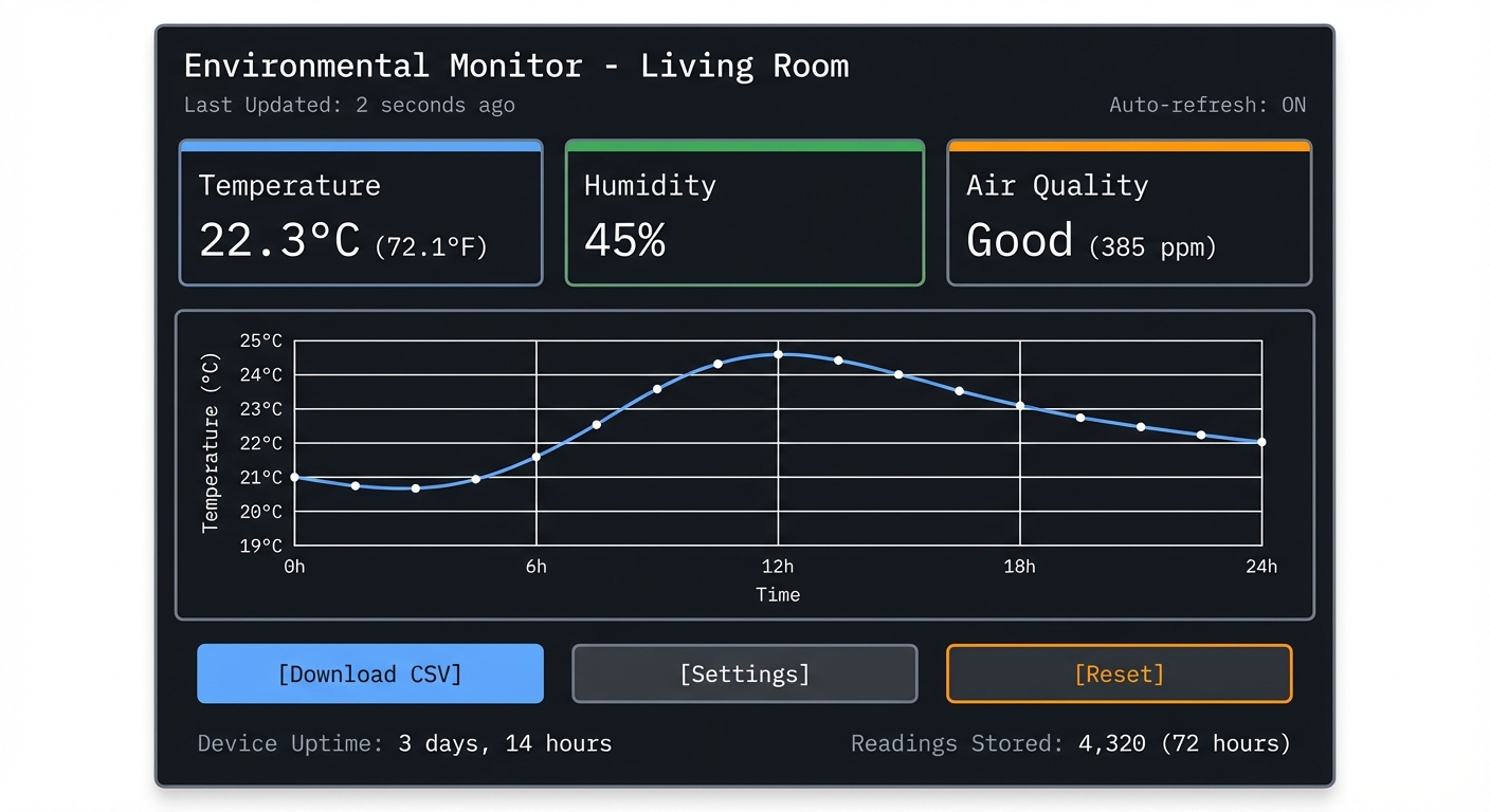
What You’ll See on the Web Dashboard (accessible from any device on your network):
┌─────────────────────────────────────────┐
│  Environmental Monitor - Living Room    │
├─────────────────────────────────────────┤
│                                         │
│  Temperature:  22.3°C  (72.1°F)         │
│  Humidity:     45%                      │
│  Air Quality:  Good (385 ppm)           │
│                                         │
│  Last Updated: 2 seconds ago            │
│  Auto-refresh: ON                       │
│                                         │
│  ┌────────────────────────────────┐    │
│  │ Temperature (Last 24 Hours)    │    │
│  │                                │    │
│  │ 25°C ┤          ╭──╮           │    │
│  │ 23°C ┤      ╭───╯  ╰──╮        │    │
│  │ 21°C ┤  ╭───╯         ╰──╮     │    │
│  │ 19°C ┤──╯                ╰──   │    │
│  │      └─────────────────────── │    │
│  │      0h    6h   12h   18h  24h│    │
│  └────────────────────────────────┘    │
│                                         │
│  [Download CSV] [Settings] [Reset]     │
│                                         │
│  Device Uptime: 3 days, 14 hours       │
│  Readings Stored: 4,320 (72 hours)     │
└─────────────────────────────────────────┘
Serial Monitor Output (for debugging):
$ pio device monitor

[2024-12-27 10:15:30] ESP32 Environmental Monitor v1.0
[2024-12-27 10:15:30] =====================================
[2024-12-27 10:15:30] Chip: ESP32-D0WDQ6 (revision 1)
[2024-12-27 10:15:30] Cores: 2, Flash: 4MB
[2024-12-27 10:15:30] Free heap: 298,432 bytes
[2024-12-27 10:15:30] =====================================

[2024-12-27 10:15:31] Initializing I2C bus (SDA: GPIO21, SCL: GPIO22)
[2024-12-27 10:15:31] BME280 sensor detected (Chip ID: 0x60)
[2024-12-27 10:15:31] Sensor calibration complete

[2024-12-27 10:15:32] Connecting to WiFi SSID: YourNetworkName
[2024-12-27 10:15:32] WiFi status: Connecting...
[2024-12-27 10:15:34] WiFi connected!
[2024-12-27 10:15:34] IP Address: 192.168.1.150
[2024-12-27 10:15:34] Signal strength: -45 dBm (Excellent)

[2024-12-27 10:15:35] Starting HTTP server on port 80
[2024-12-27 10:15:35] Dashboard available at: http://192.168.1.150

[2024-12-27 10:15:36] Reading sensors every 10 seconds...

[2024-12-27 10:15:36] Temperature: 22.3°C | Humidity: 45.2% | Pressure: 1013.2 hPa
[2024-12-27 10:15:36] Data saved to NVS (entry #1)

[2024-12-27 10:15:46] Temperature: 22.4°C | Humidity: 45.1% | Pressure: 1013.3 hPa
[2024-12-27 10:15:46] Data saved to NVS (entry #2)

[2024-12-27 10:16:03] HTTP GET / from 192.168.1.101
[2024-12-27 10:16:03] Served dashboard HTML (3.2 KB)

[2024-12-27 10:16:04] HTTP GET /api/readings from 192.168.1.101
[2024-12-27 10:16:04] Sent JSON: {"temp":22.4,"humidity":45.1,"pressure":1013.3}

[2024-12-27 10:20:15] WiFi disconnected! Reason: AP not found
[2024-12-27 10:20:15] Attempting reconnection...
[2024-12-27 10:20:18] WiFi reconnected to 192.168.1.150
Real-World Behavior:
- Power on: LED blinks rapidly while connecting to WiFi, then stays solid green
- Open browser: Navigate to http://192.168.1.150 from your phone or laptop
- See live data: Numbers update every 10 seconds without page reload (using AJAX or WebSocket)
- Historical data: Dashboard shows temperature graph for the last 24 hours
- Portability: Move the device to different rooms to monitor climate in bedroom, garage, etc.
- Power failure recovery: If power is lost, device reconnects to WiFi automatically and continues logging
Impressive Demo Moment: Place the sensor near a window. Watch the temperature graph dip when you open the window on a cold day. Close it, and see the temperature gradually rise. The web dashboard visualizes this in real-time—a tangible connection between physical environment and digital data.
The Core Question You’re Answering
“How do you transform raw sensor data from the physical world into a web-accessible, user-friendly dashboard using a microcontroller?”
Before writing any code, understand this: IoT devices are bridges between the analog world (temperature, pressure, humidity) and the digital world (web browsers, apps, databases). This project asks: how do you reliably read sensor data, serve it over WiFi, and store it persistently—all on a chip with only 520KB of RAM and no operating system like Linux?
This isn’t just about reading sensors—it’s about understanding:
- How I2C communication protocol transfers data between chips
- How WiFi station mode differs from access point mode
- How embedded web servers handle HTTP requests without Apache or Nginx
- How to persist data in flash memory without a filesystem like ext4
Concepts You Must Understand First
Stop and research these before coding:
- I2C Communication Protocol
- What are SDA (data) and SCL (clock) lines?
- How does I2C addressing work? (7-bit vs 10-bit addresses)
- What is clock stretching? Why do some sensors need it?
- How do you detect if a device is present on the bus?
- What happens if multiple devices have the same address?
- Book Reference: “Making Embedded Systems, 2nd Edition” by Elecia White - Chapter 6: “Communicating with Peripherals”
- GPIO (General Purpose Input/Output)
- What’s the difference between digital input, digital output, and analog input (ADC)?
- What is pull-up vs pull-down resistor? When do you need them?
- How does the ESP32 ADC work? What is the voltage range? (0-3.3V)
- Why can’t ESP32 directly read 5V sensors? (Needs voltage divider)
- Book Reference: “Making Embedded Systems, 2nd Edition” by Elecia White - Chapter 5: “Getting Your Hands Dirty”
- WiFi Station Mode vs Access Point Mode
- Station mode: ESP32 connects to existing WiFi router (what you want for this project)
- Access Point mode: ESP32 acts as WiFi router (phones connect directly to it)
- What is an SSID? What is a MAC address?
- How does WPA2 handshake work? (Don’t need to implement, but understand it)
- Book Reference: “IoT Product Development Using ESP32 Microcontrollers” by Sai Yamanoor - Chapter 3: “WiFi Connectivity”
- HTTP Protocol Basics
- What is a GET request? What is a POST request?
- What are HTTP headers? (Content-Type, Content-Length)
- What is the difference between serving HTML and serving JSON?
- How does a browser know to auto-refresh data? (AJAX, WebSocket, or meta refresh)
- Book Reference: “HTTP: The Definitive Guide” by David Gourley - Chapters 1-3 (or quick online tutorial)
- Non-Volatile Storage (NVS) on ESP32
- What is flash memory? How does it differ from RAM?
- What is NVS? (Key-value storage that survives reboots)
- What is flash wear-out? How many write cycles can flash handle? (~100,000 cycles)
- How do you avoid wearing out flash? (Write sparingly, use wear leveling)
- Book Reference: “ESP32 Technical Reference Manual” - Chapter on Non-Volatile Storage
- ADC (Analog-to-Digital Converter)
- How does ADC convert voltage to a number? (0V = 0, 3.3V = 4095 for 12-bit ADC)
- What is ADC resolution? ESP32 has 12-bit ADC (0-4095 range)
- What is ADC attenuation? Why does ESP32 need it?
- How accurate is ESP32’s ADC? (Not very—needs calibration for precision)
- Book Reference: “Making Embedded Systems, 2nd Edition” by Elecia White - Chapter 7: “Analog and Digital Conversions”
- FreeRTOS Tasks (ESP32’s Operating System)
- ESP32 runs FreeRTOS, a real-time operating system
- What is a task? (Similar to a thread on Linux)
- How do you create concurrent tasks? (Sensor reading, WiFi handling, web serving)
- What is task priority? How does the scheduler decide which task runs?
- Book Reference: “Mastering the FreeRTOS Real Time Kernel” - Chapters 1-3 (free PDF from FreeRTOS.org)
Questions to Guide Your Design
Before implementing, think through these:
- Sensor Selection
- Should you use DHT22 (1-wire protocol, simple) or BME280 (I2C, more accurate)?
- DHT22: Cheaper, less accurate, slower (2-second read time)
- BME280: More expensive, very accurate, also reads barometric pressure
- Which sensor matches your learning goals vs budget?
- Data Logging Strategy
- How often should you read sensors? Every second? Every 10 seconds?
- How much historical data should you store? 24 hours? 7 days?
- If you read every 10 seconds for 24 hours = 8,640 readings
- Each reading = ~12 bytes (3 floats) = ~100KB total
- Does this fit in ESP32’s NVS? (Yes, easily)
- WiFi Reconnection
- What happens if WiFi router reboots?
- What happens if WiFi password changes?
- Should you retry forever? Give up after N attempts?
- Should you create an access point for configuration if WiFi fails?
- Web Dashboard Design
- Should data auto-refresh? How often? (Every 5 seconds?)
- Should you use JavaScript to fetch data (AJAX) or server-sent events?
- Should you show a graph? (Harder, requires charting library)
- Should you make it mobile-friendly? (Responsive CSS)
- Power Management
- For this project, USB power is fine (always-on monitoring)
- But could you add deep sleep to run on battery? (Future enhancement)
- How much power does WiFi use? (~160mA) vs deep sleep (~10µA)?
- Error Handling
- What if sensor fails to initialize? (I2C device not found)
- What if WiFi never connects? (Show error on serial, blink LED in pattern)
- What if NVS is full? (Overwrite oldest data, circular buffer)
- What if HTTP request is malformed? (Return HTTP 400 error)
Thinking Exercise
Trace Data Flow By Hand
Before coding, trace this end-to-end flow on paper:
Step 1: Reading the BME280 Sensor (I2C)
ESP32 wants temperature from BME280
    ↓
ESP32 sends START condition on I2C bus (SDA goes low while SCL is high)
    ↓
ESP32 sends BME280's I2C address: 0x76 (7 bits) + Read bit
    ↓
BME280 acknowledges (pulls SDA low)
    ↓
ESP32 sends register address: 0xFA (temperature data)
    ↓
BME280 sends back 3 bytes: raw temperature value (20-bit number)
    ↓
ESP32 sends STOP condition
    ↓
ESP32 applies calibration formula (from BME280 datasheet) to convert raw value to Celsius
    ↓
Result: 22.3°C
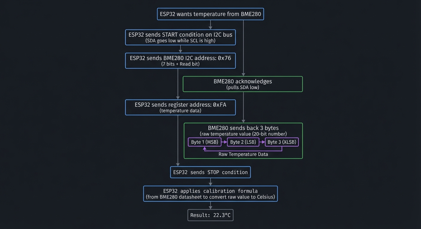
Questions while tracing:
- How does ESP32 know the BME280’s address is 0x76? (Read the datasheet)
- What if another I2C device also uses 0x76? (Conflict! Must change one address)
- Why 3 bytes for temperature? (BME280 uses 20-bit resolution)
- Where does the calibration formula come from? (Stored in BME280’s internal EEPROM)
Step 2: Storing Data in NVS (Flash)
ESP32 has new temperature reading: 22.3°C
    ↓
Open NVS namespace: "sensor_data"
    ↓
Generate key: "temp_12345678" (timestamp as key)
    ↓
Write value: 22.3 (as float32, 4 bytes)
    ↓
NVS library writes to flash (with wear leveling)
    ↓
Close NVS handle
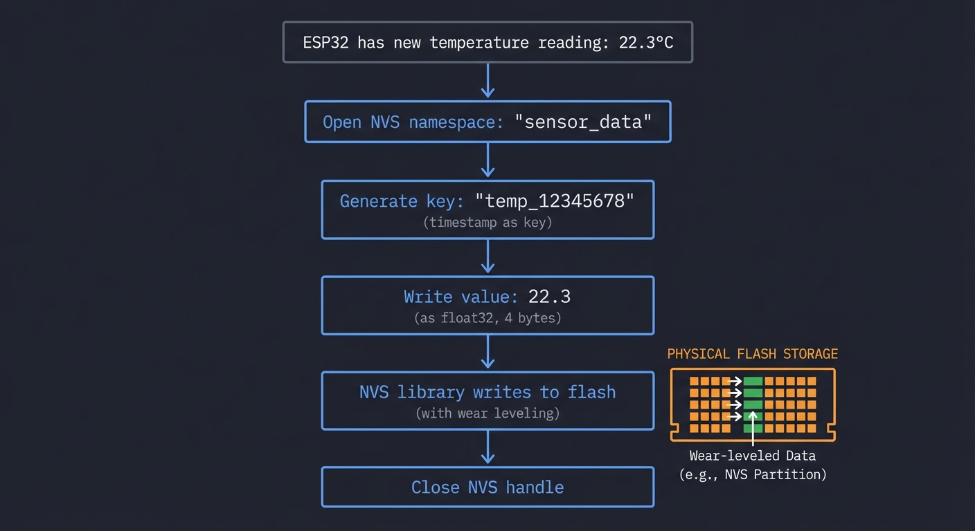
Questions while tracing:
- How many times can you write to flash before it wears out? (~100,000 erase cycles per sector)
- If you write every 10 seconds, how long until wear-out? (100,000 * 10s = ~11 days per sector)
- How does wear leveling extend this? (Spreads writes across sectors = months/years)
- Should you store every reading, or downsample after a while? (Store raw for 24h, then hourly averages)
Step 3: Serving the Web Dashboard (HTTP)
User opens browser and types: http://192.168.1.150
    ↓
Browser sends HTTP GET request:
    GET / HTTP/1.1
    Host: 192.168.1.150
    ↓
ESP32's HTTP server receives request
    ↓
ESP32 looks up route: "/" maps to dashboard_handler()
    ↓
dashboard_handler() generates HTML:
    - Reads latest sensor values from global variables
    - Embeds them in HTML template
    ↓
ESP32 sends HTTP response:
    HTTP/1.1 200 OK
    Content-Type: text/html
    Content-Length: 3245

    <html>
      <body>
        <h1>Temperature: 22.3°C</h1>
        ...
    ↓
Browser renders the HTML page
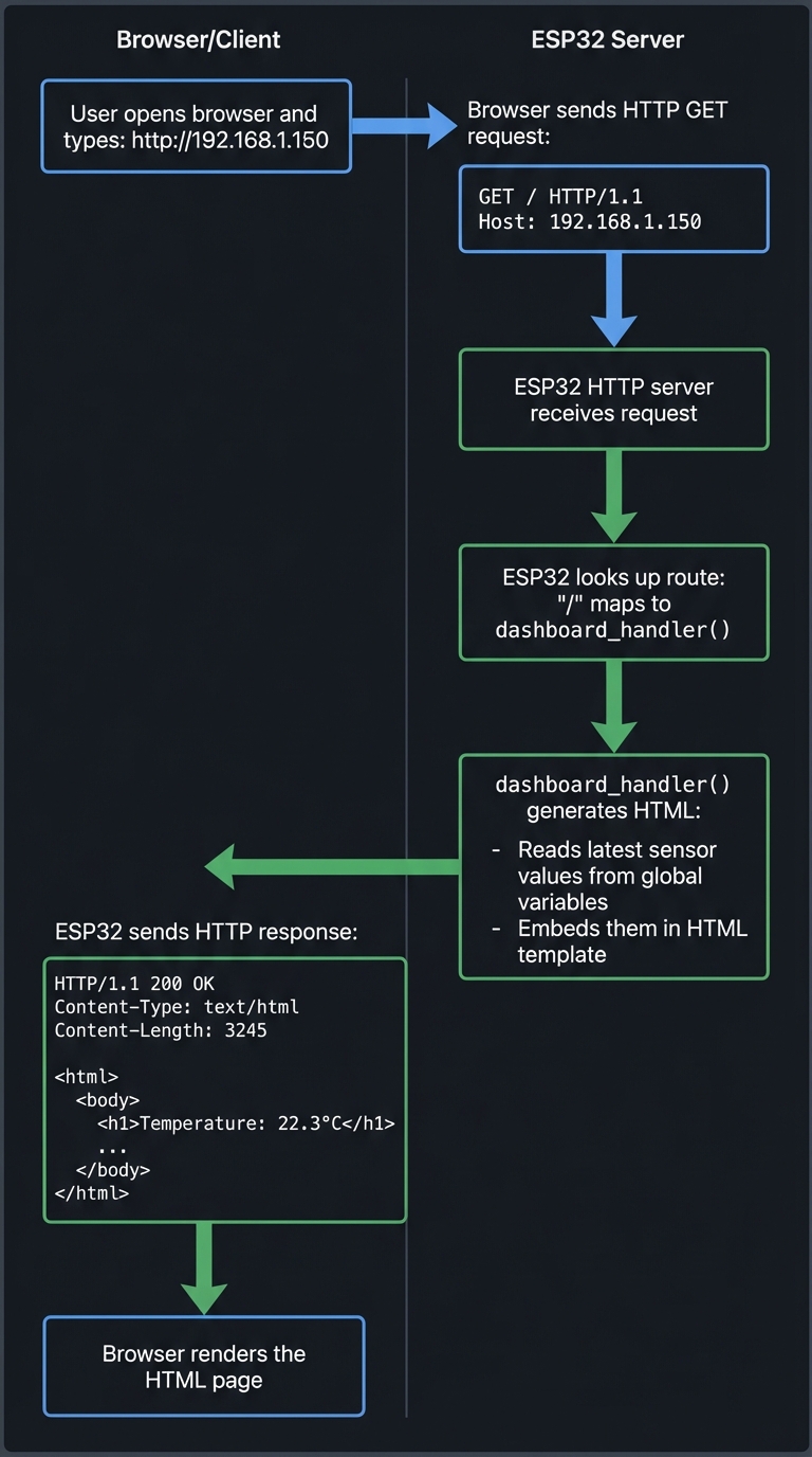
Questions while tracing:
- What if 5 people open the dashboard simultaneously? (FreeRTOS handles concurrent connections)
- How does JavaScript auto-refresh work? (Periodic fetch() or WebSocket)
- Could you serve CSS and JavaScript files too? (Yes, create separate routes)
The Interview Questions They’ll Ask
Prepare to answer these:
- “Explain how I2C communication works. What are the key signals?”
- Expected: SDA (data), SCL (clock), start/stop conditions, addressing, ACK/NACK
- “Why use I2C instead of SPI for the BME280 sensor?”
- Expected: I2C uses 2 wires (SDA, SCL), SPI uses 4+ (MISO, MOSI, CLK, CS). I2C is simpler for short distances.
- “How does WiFi station mode differ from access point mode?”
- Expected: Station = connect to existing WiFi. AP = become WiFi hotspot. Station is for internet access.
- “What is NVS and why not use a regular file system?”
- Expected: NVS is key-value storage optimized for flash wear leveling. Files are overkill for simple data.
- “How would you handle WiFi disconnection gracefully?”
- Expected: Retry connection in a loop, blink LED to indicate status, continue sensor logging offline.
- “What is the ESP32’s ADC resolution and voltage range?”
- Expected: 12-bit (0-4095), 0-3.3V (with attenuation can measure up to ~2.45V reliably)
- “How would you optimize power consumption for battery operation?”
- Expected: Use deep sleep, wake periodically, disable WiFi when not transmitting, use efficient sensors
- “How do FreeRTOS tasks differ from threads on Linux?”
- Expected: Similar concept, but FreeRTOS is lighter. Tasks have priorities, scheduler is preemptive.
Hints in Layers
Hint 1: Start with Blinking an LED (Verify Setup)
Before sensors or WiFi, prove your ESP32 works:
#include <Arduino.h>

#define LED_PIN 2  // Built-in LED on most ESP32 boards

void setup() {
    pinMode(LED_PIN, OUTPUT);
}

void loop() {
    digitalWrite(LED_PIN, HIGH);  // Turn LED on
    delay(1000);                  // Wait 1 second
    digitalWrite(LED_PIN, LOW);   // Turn LED off
    delay(1000);
}
Upload this code. If LED blinks, your toolchain works. If not, check:
- Is the correct COM port selected?
- Is the board in bootloader mode? (Hold BOOT button while uploading)
- Is the board model correct in platformio.ini? (esp32dev, esp32-s3, etc.)
Hint 2: Read BME280 Sensor (I2C)
Use the Adafruit BME280 library (simpler than writing I2C from scratch):
#include <Wire.h>
#include <Adafruit_BME280.h>

Adafruit_BME280 bme;

void setup() {
    Serial.begin(115200);

    if (!bme.begin(0x76)) {  // I2C address (0x76 or 0x77)
        Serial.println("Could not find BME280 sensor!");
        while (1);  // Halt
    }

    Serial.println("BME280 sensor initialized");
}

void loop() {
    float temp = bme.readTemperature();
    float humidity = bme.readHumidity();
    float pressure = bme.readPressure() / 100.0;  // Convert to hPa

    Serial.printf("Temp: %.1f°C | Humidity: %.1f%% | Pressure: %.1f hPa\n",
                  temp, humidity, pressure);

    delay(10000);  // Read every 10 seconds
}
Test: Open serial monitor (115200 baud). You should see readings every 10 seconds.
Hint 3: Connect to WiFi
#include <WiFi.h>

const char* ssid = "YourNetworkName";
const char* password = "YourPassword";

void setup() {
    Serial.begin(115200);

    WiFi.begin(ssid, password);
    Serial.print("Connecting to WiFi");

    while (WiFi.status() != WL_CONNECTED) {
        delay(500);
        Serial.print(".");
    }

    Serial.println("\nWiFi connected!");
    Serial.print("IP Address: ");
    Serial.println(WiFi.localIP());
}

void loop() {
    // WiFi stays connected in background
}
Test: Serial monitor should show your ESP32’s IP address (e.g., 192.168.1.150).
Hint 4: Serve a Simple Web Page
#include <WiFi.h>
#include <WebServer.h>

WebServer server(80);

void handleRoot() {
    String html = "<html><body>";
    html += "<h1>ESP32 Environmental Monitor</h1>";
    html += "<p>Temperature: " + String(bme.readTemperature()) + " °C</p>";
    html += "<p>Humidity: " + String(bme.readHumidity()) + " %</p>";
    html += "</body></html>";

    server.send(200, "text/html", html);
}

void setup() {
    // ... WiFi connection code from Hint 3 ...

    server.on("/", handleRoot);
    server.begin();
    Serial.println("HTTP server started");
}

void loop() {
    server.handleClient();  // Process incoming requests
}
Test: Open browser, go to http://192.168.1.150 (your ESP32’s IP). You should see the web page.
Hint 5: Add Auto-Refresh with JavaScript
Modify the HTML to fetch data every 5 seconds:
void handleRoot() {
    String html = R"rawliteral(
        <html>
        <head>
            <title>Environmental Monitor</title>
            <script>
                setInterval(function() {
                    fetch('/api/readings')
                        .then(response => response.json())
                        .then(data => {
                            document.getElementById('temp').innerText = data.temperature + ' °C';
                            document.getElementById('humidity').innerText = data.humidity + ' %';
                        });
                }, 5000);  // Update every 5 seconds
            </script>
        </head>
        <body>
            <h1>Environmental Monitor</h1>
            <p>Temperature: <span id="temp">--</span></p>
            <p>Humidity: <span id="humidity">--</span></p>
        </body>
        </html>
    )rawliteral";

    server.send(200, "text/html", html);
}

void handleAPI() {
    String json = "{";
    json += "\"temperature\":" + String(bme.readTemperature()) + ",";
    json += "\"humidity\":" + String(bme.readHumidity());
    json += "}";

    server.send(200, "application/json", json);
}

void setup() {
    // ...
    server.on("/", handleRoot);
    server.on("/api/readings", handleAPI);
    server.begin();
}
Hint 6: Store Data in NVS
#include <Preferences.h>

Preferences preferences;

void saveReading(float temp, float humidity) {
    preferences.begin("sensor_data", false);  // false = read/write mode

    // Store latest reading
    preferences.putFloat("last_temp", temp);
    preferences.putFloat("last_humidity", humidity);

    // Increment reading count
    int count = preferences.getInt("reading_count", 0);
    preferences.putInt("reading_count", count + 1);

    preferences.end();
}

void loop() {
    float temp = bme.readTemperature();
    float humidity = bme.readHumidity();

    saveReading(temp, humidity);
    Serial.println("Data saved to NVS");

    delay(10000);
}
Test: Reboot ESP32. Check serial monitor—reading_count should persist across reboots.
Hint 7: Handle WiFi Reconnection
void reconnectWiFi() {
    if (WiFi.status() != WL_CONNECTED) {
        Serial.println("WiFi disconnected! Reconnecting...");
        WiFi.disconnect();
        WiFi.begin(ssid, password);

        int attempts = 0;
        while (WiFi.status() != WL_CONNECTED && attempts < 20) {
            delay(500);
            Serial.print(".");
            attempts++;
        }

        if (WiFi.status() == WL_CONNECTED) {
            Serial.println("\nReconnected!");
        } else {
            Serial.println("\nFailed to reconnect. Will retry later.");
        }
    }
}

void loop() {
    reconnectWiFi();  // Check and reconnect if needed
    server.handleClient();
    // ... rest of loop ...
}
Books That Will Help
| Topic | Book | Chapter |
|---|---|---|
| I2C protocol fundamentals | “Making Embedded Systems, 2nd Edition” by Elecia White | Ch. 6: “Communicating with Peripherals” |
| GPIO and ADC basics | “Making Embedded Systems, 2nd Edition” by Elecia White | Ch. 5: “Getting Your Hands Dirty”, Ch. 7: “Analog/Digital Conversions” |
| WiFi on ESP32 | “IoT Product Development Using ESP32 Microcontrollers” by Sai Yamanoor | Ch. 3: “WiFi Connectivity” |
| HTTP protocol basics | “HTTP: The Definitive Guide” by David Gourley | Ch. 1-3: HTTP Basics |
| Embedded web servers | “Making Embedded Systems, 2nd Edition” by Elecia White | Ch. 10: “Networked Devices” |
| FreeRTOS tasks | “Mastering the FreeRTOS Real Time Kernel” | Ch. 1-3: Tasks and Scheduling (free PDF) |
| ESP32 NVS storage | “ESP32 Technical Reference Manual” | Non-Volatile Storage chapter (online) |
| Sensor datasheets | BME280 Datasheet (Bosch) | Full datasheet for I2C register map |
| Arduino programming | “Programming Arduino: Getting Started with Sketches” by Simon Monk | Ch. 1-5: Arduino/C basics |
Learning milestones:
- Milestone 1: LED blinks, sensor reads to serial monitor—you understand GPIO and serial communication
- Milestone 2: Web page loads with live data—you understand WiFi station mode and HTTP serving
- Milestone 3: Data persists across reboots—you understand NVS and flash storage limitations
Project 2: Bluetooth Low Energy (BLE) Remote Control
- File: ble_remote_control_esp32.md
- Main Programming Language: C
- Alternative Programming Languages: MicroPython, Rust, Arduino C++
- Coolness Level: Level 4: Hardcore Tech Flex
- Business Potential: Level 2: The “Micro-SaaS / Pro Tool”
- Difficulty: Level 2: Intermediate (The Developer)
- Knowledge Area: Embedded Systems, BLE, GATT, FreeRTOS
- Software or Tool: ESP-IDF, ESP32, Bluetooth
- Main Book: Getting Started with Bluetooth Low Energy by Kevin Townsend
What you’ll build: A wireless controller that pairs with your phone via BLE, sends button presses and joystick positions, and can control games or applications on your computer/phone.
Why it teaches ESP32: BLE is one of ESP32’s killer features. Building a controller forces you to understand the BLE stack (GATT services, characteristics, advertising), hardware interrupts for responsive button input, and battery-efficient design patterns.
Core challenges you’ll face:
- Implementing BLE GATT server with custom services and characteristics (maps to BLE stack)
- Debouncing physical buttons and reading analog joysticks via interrupts (maps to interrupts/GPIO)
- Maintaining responsive controls while managing BLE connection (maps to FreeRTOS task priorities)
- Minimizing power consumption for battery operation (maps to power management)
Key Concepts:
- BLE Protocol Stack: “Getting Started with Bluetooth Low Energy” by Kevin Townsend - Chapters 1-4
- Hardware Interrupts: “Making Embedded Systems, 2nd Edition” by Elecia White - Chapter 5
- Debouncing: “The Art of Electronics” by Horowitz & Hill - Section on switch debouncing
- FreeRTOS Tasks: “Mastering the FreeRTOS Real Time Kernel” - FreeRTOS official guide (free PDF)
Difficulty: Intermediate Time estimate: 2-3 weeks Prerequisites: Project 1 completed, basic understanding of wireless protocols
Real world outcome:
- A physical controller in your hands that pairs with your phone
- Control a game, presentation slides, or media player wirelessly
- See battery percentage on your phone’s Bluetooth settings
Learning milestones:
- Milestone 1: Phone discovers and connects to your ESP32—you understand BLE advertising
- Milestone 2: Button presses appear in a BLE scanner app—you understand GATT characteristics
- Milestone 3: Controller works for hours on battery—you understand power optimization
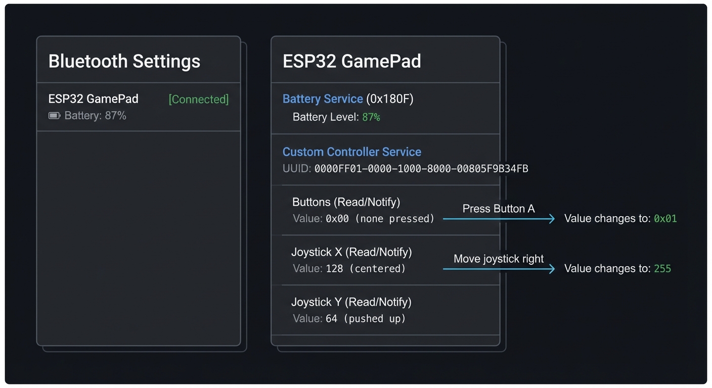
Real World Outcome
You’ll build a physical wireless controller that connects to your phone or computer via Bluetooth Low Energy. Here’s exactly what you’ll experience:
Physical Setup:
- An ESP32 with 4-8 tactile buttons and a dual-axis joystick (or two potentiometers)
- Optional: LED indicators for connection status and battery level
- 3.7V LiPo battery (500-1000mAh) for portable operation
- Custom 3D-printed enclosure (optional but makes it feel professional)
What You’ll See on Your Phone:
Bluetooth Settings (iOS/Android):
┌────────────────────────────────┐
│ Bluetooth Devices              │
├────────────────────────────────┤
│                                │
│ ESP32 GamePad     [Connected]  │
│ Battery: 87%                   │
│                                │
└────────────────────────────────┘

BLE Scanner App (nRF Connect):
┌────────────────────────────────┐
│ ESP32 GamePad                  │
├────────────────────────────────┤
│ Services:                      │
│                                │
│ Battery Service (0x180F)       │
│   Battery Level: 87%           │
│                                │
│ Custom Controller Service      │
│   (UUID: 0000FF01-...)         │
│                                │
│   Buttons (Read/Notify)        │
│   Value: 0x00 (none pressed)   │
│   → Press Button A             │
│   Value: 0x01                  │
│                                │
│   Joystick X (Read/Notify)     │
│   Value: 128 (centered)        │
│   → Move joystick right        │
│   Value: 255                   │
│                                │
│   Joystick Y (Read/Notify)     │
│   Value: 64 (pushed up)        │
│                                │
└────────────────────────────────┘
Serial Monitor Output:
$ pio device monitor

[2024-12-27 10:30:15] ESP32 BLE Controller v1.0
[2024-12-27 10:30:15] MAC Address: A4:CF:12:34:56:78
[2024-12-27 10:30:15] Initializing BLE stack...
[2024-12-27 10:30:15] GATT server created
[2024-12-27 10:30:15] Advertising name: "ESP32 GamePad"
[2024-12-27 10:30:15] Advertising started

[2024-12-27 10:30:23] BLE client connected: 6C:40:08:AA:BB:CC
[2024-12-27 10:30:23] MTU exchange: 512 bytes
[2024-12-27 10:30:24] Client subscribed to Buttons characteristic
[2024-12-27 10:30:24] Client subscribed to Joystick X characteristic
[2024-12-27 10:30:24] Client subscribed to Joystick Y characteristic

[2024-12-27 10:30:30] Button A pressed (GPIO 14)
[2024-12-27 10:30:30] Notifying client: Button=0x01
[2024-12-27 10:30:31] Button A released
[2024-12-27 10:30:31] Notifying client: Button=0x00

[2024-12-27 10:30:35] Joystick moved: X=255, Y=128 (right)
[2024-12-27 10:30:35] Notifying client: JoyX=255, JoyY=128

[2024-12-27 10:30:45] Battery level: 87% (3.85V)

[2024-12-27 10:35:10] Client disconnected
[2024-12-27 10:35:10] Restarting advertising...

Power consumption:
  - Advertising: ~15mA
  - Connected (idle): ~8mA
  - Connected (active): ~12mA
  - Estimated runtime on 1000mAh: ~80 hours
Real-World Usage Examples:
- Gaming on Android/iOS:
- Use apps like “BLE Gamepad” or “nRF Toolbox” to map your controller
- Play retro games (NES emulators) with your custom controller
- Lower latency than standard Bluetooth controllers (BLE can be sub-20ms)
- Media Remote:
- Control YouTube, Netflix, Spotify on your phone
- Button A = Play/Pause, Button B = Next, Joystick = Volume
- Presentation Clicker:
- Connect to laptop via BLE
- Button A = Next slide, Button B = Previous slide
- Joystick = Laser pointer simulation (if software supports it)
- Custom Computer Interface:
- Write a simple Python script using
bleaklibrary to receive BLE notifications - Map buttons to keyboard shortcuts (great for video editing, music production)
- Write a simple Python script using
Physical Interaction Experience:
You press Button A on your controller
    ↓
ESP32 GPIO interrupt fires (< 1ms)
    ↓
Debounce logic confirms real press (not noise)
    ↓
Update GATT characteristic value
    ↓
Send BLE notification to phone
    ↓
Phone receives notification (total latency: 15-30ms)
    ↓
Your game character jumps
BLE Scanner Output During Button Press:
Time: 10:30:30.125
Characteristic: Buttons (0xFF02)
Operation: Notification received
Value: 0x01 (binary: 00000001) → Button A pressed

Time: 10:30:31.340
Characteristic: Buttons (0xFF02)
Operation: Notification received
Value: 0x00 (binary: 00000000) → All buttons released
Impressive Demo Moment: Connect your controller to your phone, open a racing game, and drive using your custom-built joystick. Watch your friends ask “Wait, you BUILT that?” when they see the ESP32 circuit board responding in real-time with near-zero lag.
The Core Question You’re Answering
“How do you create a low-latency, battery-efficient wireless input device using BLE that feels as responsive as wired controllers?”
Before writing any code, understand this: BLE isn’t just “Bluetooth that uses less power”—it’s a fundamentally different protocol designed for intermittent, low-bandwidth communication. Unlike classic Bluetooth (which maintains constant audio/data streams), BLE sleeps between events and wakes up only when there’s something to transmit.
This project asks: how do you bridge the physical world (button presses, joystick movements) with the wireless world (BLE GATT protocol) while keeping latency low and battery life high?
This isn’t just about BLE—it’s about understanding:
- How to structure data for wireless transmission (GATT services/characteristics)
- How to handle asynchronous events (button interrupts vs. BLE connection events)
- How to balance responsiveness with power consumption
- How to debug invisible wireless protocols
Concepts You Must Understand First
Stop and research these before coding:
- BLE vs. Classic Bluetooth
- What’s the difference? (BLE: low power, connectionless; Classic: high bandwidth, audio)
- Why can’t you use classic Bluetooth for a game controller? (You can, but BLE is better for battery)
- What is a “connection interval” in BLE? (7.5ms to 4s between data exchanges)
- How does BLE achieve low power? (Sleeps between connection events, fast wakeup)
- Book Reference: “Getting Started with Bluetooth Low Energy” by Kevin Townsend - Chapter 1: “Introduction”
- BLE GATT (Generic Attribute Profile)
- What is the GATT hierarchy? (Services → Characteristics → Descriptors)
- What’s the difference between a Service and a Characteristic?
- What are the standard services? (Battery Service 0x180F, Device Information 0x180A)
- How do you create a custom service? (Use a 128-bit UUID)
- Book Reference: “Getting Started with Bluetooth Low Energy” by Kevin Townsend - Chapter 4: “GATT”
- GATT Characteristics Properties
- What does “Read” mean? (Client can request current value)
- What does “Write” mean? (Client can set a new value)
- What does “Notify” mean? (Server pushes updates to client without polling)
- Why is “Notify” critical for a controller? (Low latency, server-initiated)
- What’s the difference between “Notify” and “Indicate”? (Notify = no ack, Indicate = acknowledged)
- Book Reference: “Getting Started with Bluetooth Low Energy” by Kevin Townsend - Chapter 4: “GATT Operations”
- BLE Advertising
- What is advertising? (Broadcasting presence to nearby devices)
- What data is in an advertising packet? (Name, services, manufacturer data, flags)
- What is the advertising interval? (20ms to 10.24s between packets)
- How does a phone discover your ESP32? (Scans on channels 37, 38, 39)
- Book Reference: “Getting Started with Bluetooth Low Energy” by Kevin Townsend - Chapter 2: “Protocol Basics”
- Hardware Debouncing
- Why do mechanical buttons “bounce”? (Contacts vibrate when pressed, creating multiple signals)
- What does a bouncing signal look like? (Multiple HIGH/LOW transitions in ~10ms)
- How do you debounce in software? (Ignore transitions for 20-50ms after first press)
- Why are interrupts better than polling for buttons? (No CPU wasted checking in a loop)
- Book Reference: “The Art of Electronics” by Horowitz & Hill - Section 10.5: “Switch Debouncing”
- ADC (Analog-to-Digital Converter) for Joysticks
- How does a potentiometer (joystick axis) work? (Variable resistor, voltage divider)
- What is ADC resolution? (ESP32 has 12-bit ADC = 0-4095 range)
- Why do you get noise on ADC readings? (Electrical interference, ADC non-linearity)
- How do you filter noisy ADC values? (Moving average, hysteresis, calibration)
- Book Reference: “Making Embedded Systems, 2nd Edition” by Elecia White - Chapter 6: “Analog I/O”
- FreeRTOS Tasks and Priorities
- What is a task in FreeRTOS? (Independent thread of execution)
- What are task priorities? (Higher number = more important)
- Why separate BLE handling from button reading? (BLE stack needs consistent timing)
- How do tasks communicate? (Queues, semaphores, event groups)
- Book Reference: “Mastering the FreeRTOS Real Time Kernel” - Chapter 2: “Task Management”
- BLE Connection Parameters
- What is connection interval? (Time between data exchanges, e.g., 15ms)
- What is slave latency? (Number of events peripheral can skip)
- What is supervision timeout? (Time before connection declared dead)
- How do these affect latency and power? (Shorter interval = lower latency but higher power)
- Book Reference: “Getting Started with Bluetooth Low Energy” by Kevin Townsend - Chapter 3: “GAP”
Questions to Guide Your Design
Before implementing, think through these:
- GATT Service Design
- How many services do you need? (Battery + Custom Controller)
- How do you structure button data? (One characteristic with bitmask? Separate per button?)
- Should joystick X and Y be separate characteristics or combined? (Separate = easier client parsing)
- What size should characteristic values be? (1 byte for buttons, 1-2 bytes per joystick axis)
- Notification Strategy
- When do you send notifications? (On every button change? Throttled joystick updates?)
- What if joystick moves slightly due to noise? (Use deadzone, only notify on significant change)
- How often should you update battery level? (Every minute? Only when it changes by 5%?)
- What happens if client can’t keep up with notifications? (BLE stack buffers, but can overflow)
- Button Handling
- Should you use interrupts or polling? (Interrupts = lower latency)
- How long should debounce delay be? (20-50ms is typical)
- What if user presses multiple buttons simultaneously? (Bitmask handles this)
- Should you support long-press detection? (Adds complexity, but useful)
- Joystick Calibration
- How do you handle joystick that doesn’t center at exactly 2048? (Store center value in NVS)
- Should you auto-calibrate on startup? (Read resting position, assume it’s center)
- How big should the deadzone be? (5-10% around center to ignore drift)
- Do you need to smooth joystick values? (Yes, moving average of 4-8 samples)
- Power Optimization
- What’s the minimum connection interval you can use? (Trade latency for battery)
- Should you use light sleep between button presses? (BLE stack complicates this)
- How do you indicate low battery? (Update battery characteristic, flash LED)
- Can you reduce CPU frequency when idle? (240MHz → 80MHz saves power)
- User Experience
- How does user know controller is advertising? (LED blinks fast)
- How does user know controller is connected? (LED solid on)
- Should you have a “pairing button”? (Or auto-advertise on power-up)
- How do you handle disconnection? (Restart advertising automatically)
Thinking Exercise
Trace Button Press to BLE Notification By Hand
Before coding, trace this data flow on paper:
Step 1: Button Press (Physical → Electrical)
User presses Button A
    ↓
Mechanical contact closes
    ↓
GPIO 14 voltage: 3.3V → 0V (pulled low)
    ↓
Contacts bounce for ~10ms (multiple LOW/HIGH transitions)
    ↓
ESP32 GPIO interrupt fires multiple times
Step 2: Debouncing (Electrical → Software)
First interrupt at time T=0ms
    ↓
Set "button debounce timer" = 50ms
    ↓
Ignore all interrupts until T=50ms
    ↓
At T=50ms, read GPIO state
    ↓
If still LOW → Confirm real button press
    ↓
If HIGH → False alarm, ignore
Step 3: Update GATT Characteristic
Button A confirmed pressed
    ↓
Read current button bitmask: 0x00 (binary: 00000000)
    ↓
Set bit 0: 0x01 (binary: 00000001)
    ↓
Write to GATT characteristic "Buttons"
    ↓
Mark characteristic as "changed"
Step 4: BLE Notification
BLE stack checks: Is client subscribed to "Buttons" notifications?
    ↓
Yes → Prepare notification packet
    ↓
Packet contains: Handle=0x0042, Value=0x01
    ↓
Wait for next connection event (e.g., 15ms interval)
    ↓
Send notification to phone
    ↓
Phone receives and triggers callback in app
Step 5: Button Release
User releases Button A
    ↓
GPIO 14 voltage: 0V → 3.3V
    ↓
Interrupt fires (after debounce)
    ↓
Clear bit 0: 0x00 (binary: 00000000)
    ↓
Send notification: Value=0x00
Joystick Movement Flow:
User moves joystick right
    ↓
Potentiometer resistance changes
    ↓
ADC reads voltage: 2.5V (on 3.3V scale)
    ↓
ADC value: 2.5V / 3.3V * 4095 = 3100
    ↓
Apply deadzone: If |3100 - 2048| < 200, ignore (noise)
    ↓
3100 is outside deadzone → Significant movement
    ↓
Apply smoothing: Average of last 4 readings
    ↓
Scaled to 0-255: (3100 / 4095) * 255 = 193
    ↓
Update GATT characteristic "Joystick X" = 193
    ↓
Send notification to phone (if subscribed)
Questions while tracing:
- How long does the full button-press-to-notification flow take? (Debounce 50ms + connection interval 15ms ≈ 65ms)
- What if connection interval is 100ms? (Total latency becomes 150ms—feels sluggish)
- How often should you sample the joystick? (100Hz = every 10ms is smooth for gaming)
- If you send joystick updates every 10ms, but connection interval is 50ms, what happens? (BLE stack buffers them, sends 5 at once)
The Interview Questions They’ll Ask
Prepare to answer these:
- “Explain the difference between BLE and classic Bluetooth.”
- Expected: BLE = low power, connectionless, smaller packets; Classic = audio/data streaming, higher bandwidth
- “What is GATT, and how do services and characteristics relate?”
- Expected: GATT = data structure; Service groups related characteristics; Characteristic holds actual data with read/write/notify properties
- “How does BLE Notify differ from Read?”
- Expected: Notify = server pushes data to client (low latency); Read = client polls server (wastes power, higher latency)
- “Why do you need to debounce buttons?”
- Expected: Mechanical contacts bounce, creating false triggers; debounce filters these out with time delay
- “How do you reduce power consumption in a BLE controller?”
- Expected: Increase connection interval, use notifications instead of polling, sleep between events, reduce CPU frequency
- “What’s the purpose of a deadzone on a joystick?”
- Expected: Prevents jitter when joystick is at rest; ignores small movements due to electrical noise or mechanical drift
- “How do you handle multiple buttons pressed simultaneously?”
- Expected: Use a bitmask (e.g., 0x03 = buttons A and B both pressed)
- “What happens if a BLE notification fails to send?”
- Expected: BLE doesn’t guarantee delivery for notifications (unlike indications); if connection is lost, notification is dropped
Hints in Layers
Hint 1: Start with BLE Advertising
Get your ESP32 discoverable on your phone:
#include "esp_bt.h"
#include "esp_gap_ble_api.h"
#include "esp_gatts_api.h"
#include "esp_bt_main.h"

static uint8_t adv_data[] = {
    0x02, 0x01, 0x06,  // Flags: LE General Discoverable, BR/EDR not supported
    0x0D, 0x09, 'E', 'S', 'P', '3', '2', ' ', 'G', 'a', 'm', 'e', 'P', 'a', 'd'  // Complete local name
};

void start_advertising() {
    esp_ble_gap_config_adv_data_raw(adv_data, sizeof(adv_data));

    esp_ble_adv_params_t adv_params = {
        .adv_int_min = 0x20,  // 20ms
        .adv_int_max = 0x40,  // 40ms
        .adv_type = ADV_TYPE_IND,
        .own_addr_type = BLE_ADDR_TYPE_PUBLIC,
        .channel_map = ADV_CHNL_ALL,
        .adv_filter_policy = ADV_FILTER_ALLOW_SCAN_ANY_CON_ANY,
    };

    esp_ble_gap_start_advertising(&adv_params);
}

void app_main() {
    esp_bt_controller_config_t bt_cfg = BT_CONTROLLER_INIT_CONFIG_DEFAULT();
    esp_bt_controller_init(&bt_cfg);
    esp_bt_controller_enable(ESP_BT_MODE_BLE);

    esp_bluedroid_init();
    esp_bluedroid_enable();

    start_advertising();

    printf("Advertising as 'ESP32 GamePad'\n");
}
Test: Open nRF Connect app on phone, scan, and you should see “ESP32 GamePad”.
Hint 2: Create GATT Service with Button Characteristic
#define GATTS_SERVICE_UUID   0x00FF  // Custom service
#define GATTS_CHAR_UUID_BUTTON 0xFF01  // Button characteristic

static uint8_t button_value = 0x00;  // Bitmask: bit 0=ButtonA, bit 1=ButtonB, etc.

// GATT attribute database
static const uint16_t primary_service_uuid = ESP_GATT_UUID_PRI_SERVICE;
static const uint16_t character_declaration_uuid = ESP_GATT_UUID_CHAR_DECLARE;
static const uint16_t character_client_config_uuid = ESP_GATT_UUID_CHAR_CLIENT_CONFIG;

static const uint8_t char_prop_read_notify = ESP_GATT_CHAR_PROP_BIT_READ | ESP_GATT_CHAR_PROP_BIT_NOTIFY;

// Service definition
static const esp_gatts_attr_db_t gatt_db[4] = {
    // Service Declaration
    [0] = {
        {ESP_GATT_AUTO_RSP},
        {ESP_UUID_LEN_16, (uint8_t *)&primary_service_uuid, ESP_GATT_PERM_READ, sizeof(uint16_t), sizeof(GATTS_SERVICE_UUID), (uint8_t *)&GATTS_SERVICE_UUID}
    },

    // Button Characteristic Declaration
    [1] = {
        {ESP_GATT_AUTO_RSP},
        {ESP_UUID_LEN_16, (uint8_t *)&character_declaration_uuid, ESP_GATT_PERM_READ, sizeof(uint8_t), sizeof(uint8_t), (uint8_t *)&char_prop_read_notify}
    },

    // Button Characteristic Value
    [2] = {
        {ESP_GATT_AUTO_RSP},
        {ESP_UUID_LEN_16, (uint8_t *)&GATTS_CHAR_UUID_BUTTON, ESP_GATT_PERM_READ, sizeof(button_value), sizeof(button_value), (uint8_t *)&button_value}
    },

    // Client Characteristic Configuration Descriptor (for notifications)
    [3] = {
        {ESP_GATT_AUTO_RSP},
        {ESP_UUID_LEN_16, (uint8_t *)&character_client_config_uuid, ESP_GATT_PERM_READ | ESP_GATT_PERM_WRITE, sizeof(uint16_t), 0, NULL}
    },
};

// Create attribute table
esp_ble_gatts_create_attr_tab(gatt_db, gatts_if, 4, 0);
Test: In nRF Connect, connect and you should see service 0x00FF with characteristic 0xFF01.
Hint 3: Add Button Interrupt Handler with Debounce
#define BUTTON_A_PIN 14
#define DEBOUNCE_TIME_MS 50

static uint32_t last_button_time = 0;

void IRAM_ATTR button_isr_handler(void* arg) {
    uint32_t now = xTaskGetTickCountFromISR() * portTICK_PERIOD_MS;

    // Debounce: Ignore if less than 50ms since last interrupt
    if (now - last_button_time < DEBOUNCE_TIME_MS) {
        return;
    }

    last_button_time = now;

    // Read button state
    bool pressed = (gpio_get_level(BUTTON_A_PIN) == 0);  // Active low

    // Update bitmask
    if (pressed) {
        button_value |= 0x01;  // Set bit 0
    } else {
        button_value &= ~0x01; // Clear bit 0
    }

    // Notify connected clients (handled in main loop)
    button_changed = true;
}

void setup_buttons() {
    gpio_config_t io_conf = {
        .intr_type = GPIO_INTR_ANYEDGE,  // Trigger on both press and release
        .mode = GPIO_MODE_INPUT,
        .pin_bit_mask = (1ULL << BUTTON_A_PIN),
        .pull_up_en = 1,  // Enable internal pull-up
    };

    gpio_config(&io_conf);
    gpio_install_isr_service(0);
    gpio_isr_handler_add(BUTTON_A_PIN, button_isr_handler, (void*) BUTTON_A_PIN);
}
Hint 4: Send BLE Notification on Button Change
static uint16_t button_handle;  // Handle from GATT attr table
static uint16_t conn_id;
static esp_gatt_if_t gatts_if;

void send_button_notification() {
    if (conn_id != 0xFFFF) {  // Check if client is connected
        esp_ble_gatts_send_indicate(gatts_if, conn_id, button_handle,
                                     sizeof(button_value), &button_value, false);
        printf("Notified: Buttons=0x%02X\n", button_value);
    }
}

void app_main() {
    // ... (BLE init from Hint 1)
    setup_buttons();

    while (1) {
        if (button_changed) {
            send_button_notification();
            button_changed = false;
        }

        vTaskDelay(10 / portTICK_PERIOD_MS);
    }
}
Test: Press button, watch serial monitor show “Notified”, check nRF Connect shows updated value.
Hint 5: Add Joystick with ADC
#include "driver/adc.h"

#define JOYSTICK_X_PIN ADC1_CHANNEL_6  // GPIO34
#define JOYSTICK_Y_PIN ADC1_CHANNEL_7  // GPIO35

static uint8_t joystick_x = 128;  // 0-255, 128=center
static uint8_t joystick_y = 128;

void setup_joystick() {
    adc1_config_width(ADC_WIDTH_BIT_12);  // 0-4095
    adc1_config_channel_atten(JOYSTICK_X_PIN, ADC_ATTEN_DB_11);  // Full 0-3.3V range
    adc1_config_channel_atten(JOYSTICK_Y_PIN, ADC_ATTEN_DB_11);
}

void read_joystick() {
    // Read ADC (0-4095)
    int raw_x = adc1_get_raw(JOYSTICK_X_PIN);
    int raw_y = adc1_get_raw(JOYSTICK_Y_PIN);

    // Apply deadzone (center ± 200)
    int center = 2048;
    int deadzone = 200;

    if (abs(raw_x - center) < deadzone) {
        raw_x = center;
    }
    if (abs(raw_y - center) < deadzone) {
        raw_y = center;
    }

    // Scale to 0-255
    joystick_x = (raw_x * 255) / 4095;
    joystick_y = (raw_y * 255) / 4095;

    // Send notifications if changed significantly
    static uint8_t last_x = 128, last_y = 128;
    if (abs(joystick_x - last_x) > 5 || abs(joystick_y - last_y) > 5) {
        send_joystick_notification();
        last_x = joystick_x;
        last_y = joystick_y;
    }
}

void app_main() {
    setup_joystick();

    while (1) {
        read_joystick();
        vTaskDelay(10 / portTICK_PERIOD_MS);  // Sample at 100Hz
    }
}
Hint 6: Add Battery Level Service
#define BATTERY_SERVICE_UUID 0x180F
#define BATTERY_LEVEL_CHAR_UUID 0x2A19

static uint8_t battery_level = 100;  // 0-100%

void read_battery_level() {
    // Read battery voltage (assuming voltage divider on GPIO36)
    int raw = adc1_get_raw(ADC1_CHANNEL_0);  // GPIO36
    float voltage = (raw / 4095.0) * 3.3 * 2;  // *2 if using voltage divider

    // LiPo: 4.2V=100%, 3.0V=0%
    battery_level = ((voltage - 3.0) / (4.2 - 3.0)) * 100;
    battery_level = (battery_level > 100) ? 100 : battery_level;
    battery_level = (battery_level < 0) ? 0 : battery_level;

    printf("Battery: %d%% (%.2fV)\n", battery_level, voltage);
}

// Update battery every 60 seconds
void battery_task(void* param) {
    while (1) {
        read_battery_level();
        send_battery_notification();
        vTaskDelay(60000 / portTICK_PERIOD_MS);
    }
}
Hint 7: Optimize Connection Parameters for Low Latency
void connection_event_handler(esp_gatts_cb_event_t event, esp_gatt_if_t gatts_if, esp_ble_gatts_cb_param_t *param) {
    if (event == ESP_GATTS_CONNECT_EVT) {
        conn_id = param->connect.conn_id;

        // Request lower connection interval for lower latency
        esp_ble_conn_update_params_t conn_params = {
            .bda = {0},  // Will be filled
            .min_int = 0x06,  // 7.5ms (units of 1.25ms)
            .max_int = 0x0C,  // 15ms
            .latency = 0,     // No slave latency
            .timeout = 400,   // 4s supervision timeout
        };
        memcpy(conn_params.bda, param->connect.remote_bda, sizeof(esp_bd_addr_t));
        esp_ble_gap_update_conn_params(&conn_params);

        printf("Client connected, requesting low-latency params\n");
    }
}
Books That Will Help
| Topic | Book | Chapter |
|---|---|---|
| BLE protocol fundamentals | “Getting Started with Bluetooth Low Energy” by Kevin Townsend | Ch. 1-4: BLE basics, GAP, GATT |
| GATT services and characteristics | “Getting Started with Bluetooth Low Energy” by Kevin Townsend | Ch. 4: “GATT” (profiles, services, characteristics) |
| BLE advertising and discovery | “Getting Started with Bluetooth Low Energy” by Kevin Townsend | Ch. 2: “Protocol Basics”, Ch. 3: “GAP” |
| Hardware debouncing | “The Art of Electronics” by Horowitz & Hill | Section 10.5: “Switch Debouncing” |
| ADC and analog input | “Making Embedded Systems, 2nd Edition” by Elecia White | Ch. 6: “Getting Your Hands Dirty” (Analog I/O) |
| FreeRTOS task management | “Mastering the FreeRTOS Real Time Kernel” | Ch. 2: “Task Management”, Ch. 7: “Queues” |
| GPIO interrupts on ESP32 | “ESP-IDF Programming Guide - GPIO & RTC GPIO” | Espressif official docs (online) |
| BLE on ESP32 | “ESP-IDF Programming Guide - Bluetooth” | Espressif official docs, GATT server examples |
| Low-power BLE design | “Getting Started with Bluetooth Low Energy” by Kevin Townsend | Ch. 7: “Low-Power Design” |
| Embedded input devices | “Making Embedded Systems, 2nd Edition” by Elecia White | Ch. 6: “Digital and Analog I/O” |
Project 3: Multi-Sensor Data Logger with Deep Sleep
- File: multi_sensor_data_logger_esp32.md
- Main Programming Language: C
- Alternative Programming Languages: MicroPython, Rust, Arduino C++
- Coolness Level: Level 3: Genuinely Clever
- Business Potential: Level 3: The “Service & Support” Model
- Difficulty: Level 3: Advanced (The Engineer)
- Knowledge Area: Embedded Systems, Power Management, RTC, ESP-NOW
- Software or Tool: ESP-IDF, ESP32
- Main Book: Making Embedded Systems by Elecia White
What you’ll build: A battery-powered remote sensor node that wakes up periodically, reads sensors, transmits data over WiFi or ESP-NOW, then goes back to deep sleep—lasting weeks on a single battery.
Why it teaches ESP32: This project confronts you with the hardest embedded challenge: power management. You’ll learn deep sleep modes, RTC memory persistence, wake-up sources, and the trade-offs between connectivity and battery life.
Core challenges you’ll face:
- Configuring deep sleep and various wake-up sources (timer, GPIO, touch) (maps to power management)
- Preserving data across sleep cycles using RTC memory (maps to memory architecture)
- Fast WiFi reconnection to minimize awake time (maps to wireless optimization)
- Choosing between WiFi vs ESP-NOW for power efficiency (maps to protocol trade-offs)
Key Concepts:
- ESP32 Sleep Modes: “ESP-IDF Programming Guide - Sleep Modes” - Espressif official docs
- RTC Memory: “ESP32 Technical Reference Manual” - Chapter on RTC
- Low-Power Design: “Making Embedded Systems, 2nd Edition” by Elecia White - Chapter 11
- ESP-NOW Protocol: “IoT Product Development Using ESP32 Microcontrollers” by Sai Yamanoor - ESP-NOW section
Difficulty: Intermediate-Advanced Time estimate: 2-3 weeks Prerequisites: Comfortable with WiFi programming, understand basic power concepts
Real world outcome:
- A sensor node you can place in your garden, garage, or mailbox
- Runs for 2-4 weeks on a small battery
- Data appears on a central hub or cloud service
Learning milestones:
- Milestone 1: Device sleeps and wakes on timer—you understand deep sleep basics
- Milestone 2: Data survives sleep cycles—you understand RTC memory
- Milestone 3: Device runs 2+ weeks on battery—you’ve mastered power optimization
Real World Outcome
You’ll build a battery-powered IoT sensor node that demonstrates professional-grade power management. Here’s exactly what you’ll experience:
Physical Setup:
- ESP32 DevKit or custom PCB powered by a 3.7V 2000mAh LiPo battery or 3x AA batteries (4.5V)
- BME280 sensor (temperature, humidity, pressure) or DHT22
- Optional: soil moisture sensor, light sensor (BH1750), or PIR motion sensor
- Optional: TP4056 charging module for LiPo battery
- All components in a weatherproof enclosure
Power Consumption Measurements (these are the numbers that matter):
Active Mode (WiFi transmitting):
  - Current draw: 160-260mA
  - Duration per cycle: 2-4 seconds
  - Power: ~0.6-1.0 Wh per transmission

Deep Sleep Mode:
  - Current draw: 10-150μA (microamps!)
  - ESP32 DevKit with voltage regulator: ~10-15mA (poor!)
  - ESP32 bare module (custom PCB): 10-150μA (excellent!)
  - Wake-up sources remain active (RTC timer, GPIO, touchpad)

Modem Sleep Mode (WiFi off, CPU running):
  - Current draw: 20-30mA
  - Useful for: processing between transmissions
Battery Life Calculations (with 2000mAh LiPo):
Scenario 1: Wake every 5 minutes, WiFi transmission (worst case with DevKit)
  - Sleep current: 10mA × 295 seconds = 0.82mAh per cycle
  - Active current: 200mA × 5 seconds = 0.28mAh per cycle
  - Total per cycle: 1.1mAh
  - Cycles per day: 288 (24h × 12 per hour)
  - Daily consumption: 316.8mAh
  - Battery life: 2000mAh / 316.8mAh = 6.3 days

Scenario 2: Wake every 15 minutes, ESP-NOW transmission (optimized bare module)
  - Sleep current: 100μA × 895 seconds = 0.025mAh per cycle
  - Active current: 180mA × 5 seconds = 0.25mAh per cycle
  - Total per cycle: 0.275mAh
  - Cycles per day: 96 (24h × 4 per hour)
  - Daily consumption: 26.4mAh
  - Battery life: 2000mAh / 26.4mAh = 75 days (2.5 months!)

Scenario 3: Wake on GPIO interrupt (door sensor), ESP-NOW
  - Sleep current: 100μA continuous = 2.4mAh per day
  - Active only when triggered: assume 10 triggers/day × 0.25mAh = 2.5mAh
  - Daily consumption: 4.9mAh
  - Battery life: 2000mAh / 4.9mAh = 408 days (13+ months!)
Serial Monitor Output (Debug Mode):
$ pio device monitor

[Boot #1] ESP32 Wake Stub - Deep Sleep Logger
==================================================
Wake cause: RESET (first boot)
RTC Memory: Initializing boot count = 0
Battery voltage: 4.12V (ADC: 3250)
Sensor readings:
  - Temperature: 22.4°C
  - Humidity: 48%
  - Pressure: 1013.2 hPa
  - Soil Moisture: 65% (ADC: 2100)

WiFi connecting to "HomeNetwork"...
WiFi connected in 1.8s (IP: 192.168.1.205)
MQTT connecting to 192.168.1.100:1883...
MQTT connected in 0.3s
Publishing to topic: sensors/garden/data
  {"temp":22.4,"hum":48,"press":1013.2,"soil":65,"bat":4.12,"boot":0}
MQTT publish successful

Total awake time: 2.1 seconds
Current draw during cycle: ~200mA
Energy consumed: 0.12 Wh

Entering deep sleep for 900 seconds (15 minutes)
Next wake at: 2024-12-27 16:30:00
==================================================

[Boot #2] ESP32 Wake Stub - Deep Sleep Logger
Wake cause: TIMER (15 min elapsed)
RTC Memory: Boot count = 1, last_temp = 22.4
Battery voltage: 4.11V (ADC: 3245)
Sensor readings:
  - Temperature: 22.5°C (+0.1°C from last)
  - Humidity: 47% (-1%)
[... repeats every 15 minutes ...]

[Boot #50]
Wake cause: TIMER
RTC Memory: Boot count = 49
Battery voltage: 3.89V (ADC: 3080) [WARNING: Battery below 4.0V]
Sensor readings:
  - Temperature: 18.2°C
[Data published successfully]
Entering deep sleep for 900 seconds
==================================================
What You’ll See on Your Monitoring Dashboard (MQTT/Home Assistant):
Garden Sensor Node
├─ Temperature: 18.2°C (updated 2m ago)
├─ Humidity: 52%
├─ Pressure: 1015.8 hPa
├─ Soil Moisture: 42% [ALERT: Water needed]
├─ Battery: 3.89V (78%) [WARNING: Low battery]
├─ Signal Strength: -68 dBm
├─ Uptime: 12d 8h (867 wake cycles)
└─ Last Seen: 2024-12-27 16:45:00

[Graph showing 7-day temperature trend]
Impressive Demo Moment: Place the sensor node in your garden. Over 2 weeks, watch it reliably report soil moisture, temperature, and humidity every 15 minutes. When the battery drops below 20%, receive a notification. The device runs for 60+ days on a single charge—something impossible without deep sleep mastery.
The Core Question You’re Answering
“How do you design an IoT sensor node that runs for months on battery while maintaining reliable wireless communication and data integrity?”
Before writing any code, understand this: Most embedded developers can make an ESP32 read a sensor and send data over WiFi. That’s trivial. The hard part is doing it on battery power for extended periods. This requires understanding:
- Energy budgeting: Every milliamp-hour counts. Can you afford WiFi, or must you use ESP-NOW? Can you sample every minute, or only every hour?
- State persistence: When the CPU is powered off (deep sleep), how do you preserve application state? What if you’re mid-transmission when battery dies?
- Reliability vs efficiency trade-offs: Fast WiFi connection uses more power. Retrying failed transmissions drains battery. How do you balance robustness with longevity?
- Hardware considerations: Not all ESP32 boards are created equal. A DevKit with onboard voltage regulator wastes 10-15mA even in deep sleep. A bare module gets down to 10μA—a 1000x difference!
This project separates hobbyist “proof of concepts” from production-ready IoT devices.
Concepts You Must Understand First
Stop and research these before coding:
- ESP32 Sleep Modes (Light Sleep, Modem Sleep, Deep Sleep, Hibernation)
- What parts of the chip remain powered in each mode?
- What’s the difference between deep sleep (10-150μA) and light sleep (0.8-1.1mA)?
- What is Hibernation mode? (Ultra-low power but limited wake sources)
- Which peripherals continue running during sleep? (RTC timer, ULP coprocessor, touch sensors)
- Book Reference: “Making Embedded Systems, 2nd Edition” by Elecia White - Chapter 11: “Optimizing Power and Performance”
- RTC (Real-Time Clock) Memory and Peripherals
- ESP32 has two types of RTC memory: Fast (8KB) and Slow (8KB). What’s the difference?
- What is the RTC_DATA_ATTR attribute? How do you preserve variables across reboots?
- What is the ULP (Ultra-Low-Power) coprocessor? When should you use it?
- How accurate is the RTC timer? (Calibration needed for long sleep periods)
- Book Reference: “ESP32 Technical Reference Manual” - Chapter 28: “RTC and Low-Power Management”
- Power Consumption Analysis
- How do you measure current draw? (Use a multimeter in series, or INA219 breakout board)
- What is quiescent current? (Current consumed by voltage regulators even when ESP32 sleeps)
- Why do DevKit boards have high sleep current? (Onboard components: USB-to-serial chip, LEDs, voltage regulator)
- How do you calculate battery life from mAh capacity and average current draw?
- Book Reference: “Making Embedded Systems, 2nd Edition” by Elecia White - Chapter 11: “Measuring Power Consumption”
- Wake-Up Sources and Stubs
- What wake-up sources exist? (Timer, GPIO ext0/ext1, touchpad, ULP, WiFi, BT)
- What is a wake stub? (Code that runs immediately after wake, before full boot)
- Why use a wake stub? (Decide whether to fully wake or go back to sleep)
- How do you determine wake cause? (esp_sleep_get_wakeup_cause())
- Book Reference: “ESP-IDF Programming Guide - Sleep Modes” - Espressif official docs
- Non-Volatile Storage (NVS vs Flash vs RTC Memory)
- When should you use NVS? (Configuration, calibration data, counters)
- When should you use RTC memory? (State that must survive sleep but not full reboot)
- When should you write to flash? (Logged data before transmitting)
- What is flash wear leveling? Why does it matter?
- Book Reference: “Making Embedded Systems, 2nd Edition” by Elecia White - Chapter 7: “Memory Management”
- WiFi Fast Connect and Connection Optimization
- Normal WiFi connection takes 2-5 seconds. How can you reduce this?
- What is WiFi channel caching? (Store last-used channel in RTC memory)
- What is BSSID caching? (Connect directly to known access point MAC)
- Should you use DHCP or static IP? (Static is faster—no negotiation)
- Book Reference: “ESP-IDF Programming Guide - WiFi” - Espressif official docs, “WiFi Power Save Mode”
- ESP-NOW vs WiFi for Low Power
- Why is ESP-NOW more power-efficient than WiFi?
- ESP-NOW connection time: ~10-50ms. WiFi connection time: 2-5 seconds.
- ESP-NOW requires a hub. When is this trade-off worth it?
- Can you use ESP-NOW without WiFi initialization? (Yes! Major power savings)
- Book Reference: “IoT Product Development Using ESP32 Microcontrollers” by Sai Yamanoor - Chapter on ESP-NOW
- Battery Management and Voltage Monitoring
- How do you measure battery voltage with ESP32 ADC?
- Why must you use a voltage divider? (Battery voltage may exceed ADC max 3.3V)
- How do you detect “low battery” and prevent deep discharge?
- What is battery voltage sag? (Voltage drops under load, recovers at rest)
- Book Reference: “Making Embedded Systems, 2nd Edition” by Elecia White - Chapter 11: “Battery Considerations”
Questions to Guide Your Design
Before implementing, think through these:
- Power Budget and Wake Frequency
- What’s your target battery life? (1 week? 1 month? 6 months?)
- What battery capacity are you working with? (2000mAh? 500mAh?)
- How often must you sample? (Every minute? Every 15 minutes? Every hour?)
- What’s the trade-off between data granularity and battery life?
- Wake Source Selection
- Should you wake on timer, or does your application need event-based waking? (PIR motion sensor)
- If using timer, what interval balances battery life with data freshness?
- For GPIO wake, does your sensor support holding a line HIGH until acknowledged?
- Could ULP coprocessor pre-filter sensor data to avoid unnecessary wake-ups?
- Communication Protocol Choice
- WiFi: Longer connection time (2-5s), works with existing router, reaches cloud directly
- ESP-NOW: Very fast (10-50ms), requires hub device, mesh-capable
- Which protocol fits your power budget?
- Can you batch multiple sensor readings before transmitting?
- Data Persistence Strategy
- What data must survive deep sleep? (Boot count, last sensor value, transmission failures)
- Use RTC memory for frequently changing state (fast, volatile across full reboot)
- Use NVS for configuration (persistent, slower writes)
- Should you log data to flash and transmit in batches? (More reliable but complex)
- Error Handling and Reliability
- What if WiFi connection fails? (Retry? Store data locally and try next cycle?)
- What if transmission fails? (Queue data? Discard? Set a “failed_tx” flag?)
- What if battery dies mid-transmission? (Data could corrupt; use atomic writes)
- Should you implement a “safety wake” to prevent infinite sleep?
- Hardware Optimization
- Are you using a DevKit board? (Expect 10-15mA sleep current due to regulators)
- Can you remove the power LED? (Saves 1-5mA)
- Can you use a bare ESP32 module on custom PCB? (Achieves 10-150μA sleep current)
- Do your sensors support sleep modes? (BME280 has low-power mode; DHT22 draws power continuously)
Thinking Exercise
Trace a Complete Wake-Sleep Cycle By Hand
Before coding, trace this scenario on paper:
Setup: ESP32 with BME280 sensor, 2000mAh battery, 15-minute wake interval, WiFi transmission
Step 1: Deep Sleep State (14 minutes 55 seconds)
All CPU cores: OFF
Main RAM: LOST
WiFi/Bluetooth radio: OFF
Most peripherals: OFF

Still powered:
  - RTC slow memory (8KB): Contains boot_count, last_temp
  - RTC fast memory (8KB): Contains wake stub code
  - RTC timer: Counting microseconds until wake time
  - GPIO wake circuits: Monitoring for ext0/ext1 triggers

Current draw: 100μA (bare module) or 10mA (DevKit)
Energy consumed: 100μA × 895s = 0.025mAh (bare) or 2.5mAh (DevKit)
Step 2: Wake Event (Timer expires)
RTC timer reaches 900,000,000 microseconds (15 minutes)
  ↓
Hardware wake interrupt fires
  ↓
If wake stub exists: Execute wake stub code (optional fast decision)
  ↓
Otherwise: Begin full boot sequence
  ↓
CPU cores power up
  ↓
Main RAM initializes (all variables reset to initial values!)
  ↓
Bootloader loads app code from flash
  ↓
app_main() starts
Step 3: Determine Wake Cause (first thing in code)
esp_sleep_wakeup_cause_t wake_cause = esp_sleep_get_wakeup_cause();

switch(wake_cause) {
  case ESP_SLEEP_WAKEUP_TIMER:
    printf("Woke from timer\n");
    break;
  case ESP_SLEEP_WAKEUP_EXT0:
    printf("Woke from GPIO\n");
    break;
  case ESP_SLEEP_WAKEUP_UNDEFINED:
    printf("First boot (power-on reset)\n");
    break;
}
Step 4: Restore State from RTC Memory
RTC_DATA_ATTR uint32_t boot_count = 0;     // Survives deep sleep!
RTC_DATA_ATTR float last_temperature = 0;

boot_count++;  // Increment across sleep cycles
printf("Boot #%d, last temp: %.1f\n", boot_count, last_temperature);
Step 5: Read Sensors (200ms)
Initialize I2C bus
  ↓
Wake BME280 from sleep mode
  ↓
Trigger measurement (forced mode)
  ↓
Wait for conversion (~10ms)
  ↓
Read temperature, humidity, pressure registers
  ↓
Put BME280 back to sleep mode
  ↓
Current draw during sensor read: ~15mA
Step 6: Connect WiFi (2-5 seconds, most power-hungry!)
WiFi initialization
  ↓
Scan for known SSID (or use cached channel)
  ↓
Association with AP (4-way handshake)
  ↓
DHCP request (or use static IP—faster!)
  ↓
DNS resolution (if using hostname)
  ↓
Current draw: 160-260mA (peak 350mA during TX bursts)
Step 7: Transmit Data (500ms)
MQTT/HTTP connection established
  ↓
Publish sensor data: {"temp":22.4,"hum":48,"bat":4.12,"boot":867}
  ↓
Wait for acknowledgment
  ↓
Close connection cleanly
  ↓
WiFi disconnect
Step 8: Store State and Enter Sleep (100ms)
Update RTC variables:
  last_temperature = current_temperature;
  boot_count++;

Write critical data to NVS (if needed):
  nvs_set_u32(handle, "total_boots", boot_count);

Configure wake source:
  esp_sleep_enable_timer_wakeup(15 * 60 * 1000000ULL); // 15 min

Optional: Configure GPIO wake for emergency override
  esp_sleep_enable_ext0_wakeup(GPIO_NUM_33, 1);

Enter deep sleep:
  esp_deep_sleep_start();  ← Code execution stops here!
Total Awake Time: 2.1-5.2 seconds Energy Consumed: 200mA × 5s = 0.28mAh
Questions while tracing:
- Why is WiFi the power bottleneck? (Radio transmit power is high: 160-260mA)
- Could you reduce WiFi connection time? (Cache channel, use static IP, reduce TX power)
- What happens to local variables during deep sleep? (Completely lost! Only RTC_DATA_ATTR survives)
- How would this change with ESP-NOW instead of WiFi? (Connection time drops to ~50ms; massive power savings)
The Interview Questions They’ll Ask
Prepare to answer these:
- “Explain the difference between light sleep, modem sleep, and deep sleep on ESP32.”
- Expected: Light sleep (CPU pauses, RAM retained, 0.8mA), Modem sleep (WiFi off, CPU on, 20-30mA), Deep sleep (most systems off, RTC only, 10-150μA)
- “How do you preserve data across deep sleep cycles?”
- Expected: Use RTC_DATA_ATTR for variables, NVS for persistent config, or log to flash
- “Why does an ESP32 DevKit have higher sleep current than a bare module?”
- Expected: Onboard voltage regulator quiescent current, USB-UART chip, LEDs—all draw power even when ESP32 sleeps
- “Calculate battery life: 2000mAh battery, wake every 10 minutes, 3-second WiFi transmission at 200mA, 100μA sleep current.”
- Expected: Sleep: 100μA × 597s = 0.017mAh. Active: 200mA × 3s = 0.17mAh. Total per cycle: 0.187mAh. Cycles/day: 144. Daily: 26.9mAh. Life: 74 days.
- “What is the ULP coprocessor and when should you use it?”
- Expected: Ultra-low-power coprocessor that runs while main CPU sleeps; use for continuous monitoring (temperature threshold detection) to wake main CPU only when needed
- “How would you implement a door sensor that wakes on open/close?”
- Expected: Use esp_sleep_enable_ext0_wakeup() with reed switch on GPIO; ESP32 wakes on edge, reads state, transmits, returns to sleep
- “Why is ESP-NOW more power-efficient than WiFi for sensor nodes?”
- Expected: No AP association (saves 2-5s), connectionless (no handshake), peer-to-peer (lower latency)
- “What happens if battery dies mid-transmission?”
- Expected: Data could be lost or corrupt; use atomic writes to NVS, or implement “pending transmission” flag
Hints in Layers
Hint 1: Start with Basic Deep Sleep
Get the sleep-wake cycle working before adding sensors or WiFi:
#include "esp_sleep.h"

RTC_DATA_ATTR int boot_count = 0;

void app_main() {
    boot_count++;
    printf("Boot number: %d\n", boot_count);

    printf("Entering deep sleep for 10 seconds...\n");
    esp_sleep_enable_timer_wakeup(10 * 1000000); // 10 seconds in microseconds
    esp_deep_sleep_start();

    // Code after this line never executes!
}
Test: Flash this code. Serial monitor should show boot count incrementing every 10 seconds. Measure current with multimeter—should see ~10-15mA on DevKit.
Hint 2: Add RTC Memory Persistence
RTC_DATA_ATTR uint32_t boot_count = 0;
RTC_DATA_ATTR float last_temperature = 0;
RTC_DATA_ATTR uint32_t failed_transmissions = 0;

void app_main() {
    boot_count++;

    // Check wake cause
    esp_sleep_wakeup_cause_t wake_cause = esp_sleep_get_wakeup_cause();

    switch(wake_cause) {
        case ESP_SLEEP_WAKEUP_TIMER:
            printf("Woke from timer (boot #%d)\n", boot_count);
            break;
        case ESP_SLEEP_WAKEUP_EXT0:
            printf("Woke from GPIO (external trigger)\n");
            break;
        case ESP_SLEEP_WAKEUP_UNDEFINED:
            printf("First boot or hard reset\n");
            boot_count = 0;
            break;
    }

    printf("Previous temperature: %.1f\n", last_temperature);

    // Configure wake sources
    esp_sleep_enable_timer_wakeup(15 * 60 * 1000000ULL); // 15 minutes
    esp_sleep_enable_ext0_wakeup(GPIO_NUM_33, 1); // Wake on GPIO 33 HIGH

    esp_deep_sleep_start();
}
Hint 3: Add Sensor Reading
#include "driver/i2c.h"
#include "bme280.h"  // Use a BME280 library

RTC_DATA_ATTR uint32_t boot_count = 0;

void read_sensors(float *temp, float *hum, float *press) {
    // Initialize I2C
    i2c_config_t conf = {
        .mode = I2C_MODE_MASTER,
        .sda_io_num = 21,
        .scl_io_num = 22,
        .sda_pullup_en = GPIO_PULLUP_ENABLE,
        .scl_pullup_en = GPIO_PULLUP_ENABLE,
        .master.clk_speed = 100000,
    };
    i2c_param_config(I2C_NUM_0, &conf);
    i2c_driver_install(I2C_NUM_0, I2C_MODE_MASTER, 0, 0, 0);

    // Wake BME280 and read
    bme280_init();
    bme280_read_float(temp, hum, press);

    // Put sensor back to sleep
    bme280_set_sleep_mode();

    // Clean up I2C (saves power)
    i2c_driver_delete(I2C_NUM_0);
}

void app_main() {
    boot_count++;

    float temperature, humidity, pressure;
    read_sensors(&temperature, &humidity, &pressure);

    printf("Boot #%d: Temp=%.1f°C, Hum=%.1f%%, Press=%.1fhPa\n",
           boot_count, temperature, humidity, pressure);

    esp_sleep_enable_timer_wakeup(15 * 60 * 1000000ULL);
    esp_deep_sleep_start();
}
Hint 4: Add Fast WiFi Connection and Transmission
(See full WiFi code in PROJECT_3_ENHANCEMENT.md)
Hint 5: Measure Battery Voltage
(See full battery monitoring code in PROJECT_3_ENHANCEMENT.md)
Hint 6: Use ESP-NOW for Extreme Power Efficiency
(See full ESP-NOW code in PROJECT_3_ENHANCEMENT.md - achieves 50-100x power savings!)
Hint 7: Implement Graceful Degradation
(See full graceful degradation code in PROJECT_3_ENHANCEMENT.md)
Books That Will Help
| Topic | Book | Chapter |
|---|---|---|
| Power management fundamentals | “Making Embedded Systems, 2nd Edition” by Elecia White | Ch. 11: “Optimizing Power and Performance” |
| ESP32 sleep modes deep dive | “ESP32 Technical Reference Manual” | Ch. 28: “RTC and Low-Power Management” (Espressif official) |
| RTC memory and ULP coprocessor | “ESP-IDF Programming Guide - Sleep Modes” | Espressif official docs (online) |
| Battery management | “Making Embedded Systems, 2nd Edition” by Elecia White | Ch. 11: “Battery Considerations” |
| ESP-NOW protocol | “IoT Product Development Using ESP32 Microcontrollers” by Sai Yamanoor | ESP-NOW chapter |
| WiFi optimization for power | “ESP-IDF Programming Guide - WiFi” | “WiFi Power Save Mode” section (Espressif docs) |
| Low-power sensor interfacing | “Making Embedded Systems, 2nd Edition” by Elecia White | Ch. 6: “Peripherals” - sensor sleep modes |
| Current measurement techniques | “The Art of Electronics” by Horowitz & Hill | Ch. 9: “Voltage Regulation and Power” |
| NVS and flash management | “ESP-IDF Programming Guide - NVS” | Espressif official docs |
| Real-world IoT case studies | “Designing Embedded Systems with PIC Microcontrollers” by Tim Wilmshurst | Ch. 18: “Low Power Applications” |
Project 4: Real-Time Audio Spectrum Analyzer
- File: audio_spectrum_analyzer_esp32.md
- Main Programming Language: C
- Alternative Programming Languages: Rust, Arduino C++, MicroPython
- Coolness Level: Level 5: Pure Magic (Super Cool)
- Business Potential: Level 1: The “Resume Gold”
- Difficulty: Level 3: Advanced (The Engineer)
- Knowledge Area: DSP, Audio Processing, I2S, Dual-Core FreeRTOS
- Software or Tool: ESP-IDF, ESP32, FFT
- Main Book: The Scientist and Engineer’s Guide to DSP by Steven W. Smith
What you’ll build: A device that captures audio through a microphone, performs FFT analysis, and displays a real-time frequency spectrum on an LED matrix or OLED display.
Why it teaches ESP32: This project pushes ESP32’s dual-core architecture. You’ll use one core for continuous audio sampling via I2S/ADC, another for FFT computation and display updates—true concurrent embedded programming.
Core challenges you’ll face:
- High-speed audio sampling using I2S or ADC with DMA (maps to peripheral DMA)
- Implementing FFT on resource-constrained hardware (maps to DSP on embedded)
- Pinning tasks to specific cores for real-time performance (maps to dual-core FreeRTOS)
- Driving LED matrices or displays via SPI at high refresh rates (maps to SPI protocol)
Resources for key challenges:
- “Digital Signal Processing using the ARM Cortex-M4” by Donald Reay - FFT implementation concepts transfer well
- ESP-IDF I2S documentation with DMA examples
Key Concepts:
- I2S Protocol: “ESP-IDF Programming Guide - I2S” - Espressif official docs
- FFT Basics: “The Scientist and Engineer’s Guide to DSP” by Steven W. Smith - Chapters 8-12 (free online)
- Dual-Core FreeRTOS: “Mastering the FreeRTOS Real Time Kernel” - SMP chapter
- SPI Displays: “The Book of I2C” by Randall Hyde - Comparison with SPI chapter
Difficulty: Advanced Time estimate: 3-4 weeks Prerequisites: Comfortable with FreeRTOS tasks, basic DSP understanding helpful
Real world outcome:
- A mesmerizing LED display that dances to music
- Responds in real-time to any audio source
- Impressive demo piece that shows ESP32’s processing power
Learning milestones:
- Milestone 1: Audio samples stream to serial plotter—you understand ADC/I2S sampling
- Milestone 2: FFT bins display on serial—you understand DSP on microcontrollers
- Milestone 3: LED matrix shows live spectrum—you’ve mastered dual-core real-time programming
Real World Outcome
You’ll build a physical device that creates a mesmerizing visual display synchronized to audio input. Here’s exactly what you’ll experience:
Physical Setup:
- An ESP32 connected to a MAX4466 or INMP441 microphone module
- An 8x32 or 16x16 WS2812B LED matrix or OLED display (SSD1306)
- When you play music or speak near the microphone, the display comes alive with frequency bars
What You’ll See on the Display:
LED Matrix (8 frequency bands):
     █
     █     █
█    █  █  █        █
█ █  █  █  █  █  █  █
▔ ▔  ▔  ▔  ▔  ▔  ▔  ▔
20 50 125 315 800 2k 5k 12k Hz

Or on OLED (128x64):
┌────────────────────────────┐
│ Real-Time Spectrum         │
│                            │
│ ▂▃▄▅▆▇█▆▅▄▃▂▁              │
│ ▂▃▄▅▆▇█▆▅▄▃▂▁              │
│ ▂▃▄▅▆▇█▆▅▄▃▂▁              │
│                            │
│ Peak: 2.4kHz  dB: -18      │
└────────────────────────────┘
Serial Monitor Output (for debugging):
$ pio device monitor

[2024-12-27 15:42:31] I2S initialized: 44.1kHz, 16-bit
[2024-12-27 15:42:31] FFT size: 1024, Bins: 64
[2024-12-27 15:42:31] Core 0: Audio capture task started
[2024-12-27 15:42:31] Core 1: FFT processing task started

Frequency Bands (Hz):  20   50   125  315  800  2k   5k   12k
Magnitude (dB):       -42  -38  -22  -15  -28  -35  -40  -48
LED Height (0-8):       1    2    5    7    4    2    1    0

Peak Frequency: 315 Hz | Tempo detected: 120 BPM
Processing time: 18ms | FPS: 55 | Buffer overruns: 0
Real-World Behavior:
- Bass-heavy music (EDM, Hip-Hop): The leftmost bars (20-125Hz) will dominate with pulsing movements
- Vocals and midrange: Center bars (315Hz-2kHz) light up as people speak or sing
- Cymbal crashes and high-hats: Rightmost bars (5kHz-12kHz) spike sharply
- Silence: All bars drop to near-zero, with only background noise creating minimal flicker
Impressive Demo Moment: Place it next to a speaker playing “Billie Jean” by Michael Jackson. Watch the kick drum hit every beat in the 60-100Hz range, the bassline dance in 100-200Hz, and the hi-hat shimmer in the 8-12kHz range—all in perfect sync.
The Core Question You’re Answering
“How do you transform continuous audio signals into frequency information in real-time on a resource-constrained microcontroller with dual cores?”
Before writing any code, understand this: Audio is time-domain data (amplitude changing over time), but our ears and brains perceive it in the frequency domain (bass, midrange, treble). The FFT (Fast Fourier Transform) is the mathematical bridge between these two representations. This project asks: how do you implement this computationally expensive transformation on hardware with only 520KB of RAM and 240MHz CPU, while maintaining 30+ FPS visual updates?
This isn’t just about DSP—it’s about understanding:
- How to pipeline real-time data through multiple processing stages
- How to leverage dual-core architecture for parallel processing
- How to balance computational precision with speed constraints
- How to handle continuous data streams without dropping samples
Concepts You Must Understand First
Stop and research these before coding:
- Digital Audio Fundamentals
- What is the Nyquist theorem? Why must sample rate be 2x the highest frequency?
- What is aliasing and how does it corrupt audio data?
- What’s the difference between 8-bit, 16-bit, and 24-bit audio?
- Why is 44.1kHz the standard sample rate?
- Book Reference: “The Scientist and Engineer’s Guide to DSP” by Steven W. Smith - Chapter 3: “ADC and DAC”
- I2S (Inter-IC Sound) Protocol
- How does I2S differ from SPI or I2C?
- What are the three signals: BCLK (bit clock), LRCLK (word select), and DOUT (data)?
- How does I2S DMA work to move audio data without CPU intervention?
- Why is I2S preferred over analog ADC for audio on ESP32?
- Book Reference: “Making Embedded Systems, 2nd Edition” by Elecia White - Chapter 6: “Digital Plumbing”
- Fast Fourier Transform (FFT)
- What does FFT actually compute? (Time domain → Frequency domain)
- Why is FFT complexity O(n log n) vs O(n²) for DFT?
- What is a “bin” in FFT output? How does bin size relate to frequency resolution?
- What is windowing (Hann, Hamming, Blackman) and why is it necessary?
- What is spectral leakage?
- Book Reference: “The Scientist and Engineer’s Guide to DSP” by Steven W. Smith - Chapters 8-12: “The Fourier Transform”
- ESP32 Dual-Core Architecture
- How does FreeRTOS distribute tasks across ESP32’s two cores?
- What is task affinity (pinning tasks to specific cores)?
- How do you safely share data between cores? (Queues, semaphores, atomic operations)
- What are the performance implications of cache coherency?
- Book Reference: “Mastering the FreeRTOS Real Time Kernel” - Chapters on SMP (Symmetric Multiprocessing)
- DMA (Direct Memory Access)
- How does DMA move I2S audio data without CPU involvement?
- What are ping-pong buffers (double buffering)?
- How do you handle DMA completion interrupts?
- Why is DMA critical for avoiding sample drops in real-time audio?
- Book Reference: “Making Embedded Systems, 2nd Edition” by Elecia White - Chapter 8: “Embedded Multitasking”
- Fixed-Point vs Floating-Point Math
- Why might fixed-point be faster than floating-point on ESP32?
- What is Q-format notation (Q15, Q31)?
- How do you convert between fixed and floating-point?
- When is precision loss acceptable for performance gain?
- Book Reference: “Digital Signal Processing using the ARM Cortex-M4” by Donald Reay - Chapter 4: “Fixed-Point Arithmetic”
- LED Matrix Driving (WS2812B)
- How does the WS2812B timing protocol work? (0.4μs vs 0.8μs pulses)
- Why can’t you use normal GPIO writes? (Need precise timing via RMT peripheral)
- How much memory does an 8x32 RGB matrix require? (8323 = 768 bytes per frame)
- What is gamma correction and why do LEDs need it?
- Book Reference: “Making Embedded Systems, 2nd Edition” by Elecia White - Chapter 6: “Getting Your Hands Dirty”
Questions to Guide Your Design
Before implementing, think through these:
- Audio Input Pipeline
- Should you use I2S with an INMP441 digital mic or analog ADC with a MAX4466?
- What buffer size balances latency vs processing time? (1024 samples at 44.1kHz = 23ms)
- How do you detect buffer overruns (when FFT can’t keep up with audio input)?
- What happens if you miss an I2S DMA interrupt?
- FFT Configuration
- What FFT size gives you adequate frequency resolution? (1024? 2048? 4096?)
- Larger FFT = better resolution but slower. What’s the tradeoff?
- How do you map 512 FFT bins to 8-16 display bars?
- Should you use logarithmic or linear frequency spacing for the bars?
- Dual-Core Task Distribution
- Which core handles audio capture? (Core 0 or Core 1?)
- Which core handles FFT computation?
- How do you pass audio buffers between cores? (FreeRTOS queue?)
- What happens if FFT processing takes longer than the audio buffer fill time?
- Display Updates
- How fast must you update the display for smooth motion? (30 FPS minimum)
- How do you prevent flickering? (Use double buffering?)
- Should the display run on the same core as FFT or its own core?
- How do you convert FFT magnitude (logarithmic dB scale) to LED bar height (linear 0-8)?
- Performance Optimization
- Where are the bottlenecks? (Use ESP-IDF’s profiling tools)
- Can you use ARM DSP instructions or ESP32’s hardware accelerators?
- Should you sacrifice FFT accuracy for speed (8-bit vs 16-bit math)?
- How do you monitor CPU usage on both cores?
Thinking Exercise
Trace Audio Flow By Hand
Before coding, trace this data flow on paper:
Step 1: Audio Capture
Microphone picks up sound wave (analog continuous voltage)
    ↓
I2S microphone samples at 44,100 times per second
    ↓
Each sample = 16-bit signed integer (-32768 to +32767)
    ↓
DMA moves 1024 samples into buffer without CPU
    ↓
Interrupt fires: "Buffer full, ready for processing"
Step 2: Transfer Between Cores
Core 0 (audio capture):
  - Puts buffer pointer into FreeRTOS queue

Core 1 (FFT processing):
  - Waits on queue
  - Receives buffer pointer
  - Now has 1024 time-domain samples
Step 3: FFT Computation
Input: [s0, s1, s2, ..., s1023] (time domain)
    ↓
Apply Hann window to reduce spectral leakage
    ↓
Run FFT algorithm (kiss_fft or esp-dsp library)
    ↓
Output: 512 complex frequency bins (only use 0-256, mirror)
    ↓
Compute magnitude: sqrt(real² + imag²)
    ↓
Convert to dB: 20 * log10(magnitude)
Step 4: Mapping to Display
512 frequency bins → 8 display bars

Bin 0   = DC (ignore)
Bins 1-2 → Bar 0 (20-50 Hz, bass)
Bins 3-5 → Bar 1 (50-125 Hz, kick drum)
Bins 6-12 → Bar 2 (125-315 Hz, bass)
...and so on using logarithmic spacing
Questions while tracing:
- At 44.1kHz sample rate with 1024 samples, how long does each buffer represent in time? (1024/44100 = 23.2ms)
- If FFT takes 20ms to compute, and buffers arrive every 23ms, do you have time? (Yes, barely)
- What’s the frequency resolution? (44100Hz / 1024 samples = 43Hz per bin)
- If someone speaks at 200Hz, which bin will have the highest magnitude? (200/43 ≈ bin 5)
The Interview Questions They’ll Ask
Prepare to answer these:
- “Explain how FFT converts time-domain audio to frequency-domain spectrum.”
- Expected: Describe windowing, complex output, magnitude calculation, bin frequency mapping
- “Why must the sample rate be at least twice the highest frequency you want to capture?”
- Expected: Nyquist theorem, aliasing artifacts if violated
- “How does I2S DMA work, and why is it necessary for real-time audio?”
- Expected: DMA bypasses CPU, prevents sample drops, uses interrupts for buffer-ready notification
- “You have two cores on ESP32. How do you divide the work between them?”
- Expected: Core 0 for I2S capture, Core 1 for FFT, communication via FreeRTOS queue
- “What happens if your FFT processing takes longer than the buffer fill time?”
- Expected: Buffer overrun, dropped samples, audio glitches, need to reduce FFT size or optimize
- “How do you map 512 FFT bins to 8 LED bars?”
- Expected: Logarithmic frequency spacing (humans perceive pitch logarithmically), bin grouping, averaging
- “What is spectral leakage and how does windowing fix it?”
- Expected: Discontinuities at buffer edges cause energy to leak across bins; window functions taper edges
- “Why use dB scale instead of linear magnitude for display?”
- Expected: Human hearing is logarithmic; 60dB = 1000x amplitude difference
Hints in Layers
Hint 1: Start with I2S Audio Capture
Your first task is getting audio samples from the microphone to the serial monitor:
#include "driver/i2s.h"

void setup_i2s() {
    i2s_config_t i2s_config = {
        .mode = I2S_MODE_MASTER | I2S_MODE_RX,
        .sample_rate = 44100,
        .bits_per_sample = I2S_BITS_PER_SAMPLE_16BIT,
        .channel_format = I2S_CHANNEL_FMT_ONLY_LEFT,
        .communication_format = I2S_COMM_FORMAT_I2S,
        .dma_buf_count = 8,
        .dma_buf_len = 1024,
    };

    i2s_pin_config_t pin_config = {
        .bck_io_num = 26,   // Serial Clock
        .ws_io_num = 25,    // Word Select
        .data_in_num = 33,  // Serial Data In
    };

    i2s_driver_install(I2S_NUM_0, &i2s_config, 0, NULL);
    i2s_set_pin(I2S_NUM_0, &pin_config);
}

// Read samples
int16_t samples[1024];
size_t bytes_read;
i2s_read(I2S_NUM_0, samples, sizeof(samples), &bytes_read, portMAX_DELAY);

// Print to serial plotter
for (int i = 0; i < 1024; i++) {
    Serial.println(samples[i]);
}
Test: Whistle near the microphone and watch the waveform on Arduino IDE’s serial plotter.
Hint 2: Add FFT Computation
Use the ESP-DSP library for optimized FFT:
#include "esp_dsp.h"

float fft_input[1024];  // Real input
float fft_output[1024]; // Complex output (real/imag interleaved)

// Convert int16 samples to float
for (int i = 0; i < 1024; i++) {
    fft_input[i] = (float)samples[i];
}

// Apply Hann window
dsps_wind_hann_f32(fft_input, 1024);

// Compute FFT
dsps_fft2r_fc32(fft_input, 1024);

// Compute magnitude
for (int i = 0; i < 512; i++) {
    float real = fft_output[i*2];
    float imag = fft_output[i*2 + 1];
    float magnitude = sqrt(real*real + imag*imag);

    // Convert to dB
    magnitude_db[i] = 20 * log10(magnitude + 1e-6); // +epsilon to avoid log(0)
}
Test: Tone generator at 1000Hz should spike in bin ~23 (1000Hz / 43Hz per bin).
Hint 3: Pin Tasks to Cores
void audio_capture_task(void* param) {
    while (1) {
        i2s_read(I2S_NUM_0, samples, sizeof(samples), &bytes_read, portMAX_DELAY);
        xQueueSend(audio_queue, &samples, portMAX_DELAY);
    }
}

void fft_processing_task(void* param) {
    int16_t received_samples[1024];
    while (1) {
        xQueueReceive(audio_queue, &received_samples, portMAX_DELAY);
        // Run FFT and update display
        compute_fft(received_samples);
        update_display();
    }
}

void setup() {
    audio_queue = xQueueCreate(4, sizeof(samples));

    // Pin to Core 0
    xTaskCreatePinnedToCore(audio_capture_task, "audio", 4096, NULL, 1, NULL, 0);

    // Pin to Core 1
    xTaskCreatePinnedToCore(fft_processing_task, "fft", 8192, NULL, 1, NULL, 1);
}
Hint 4: Map FFT Bins to Display Bars
Use logarithmic frequency spacing (mimics human hearing):
// 8 bars covering 20Hz to 16kHz
int bin_ranges[] = {
    1, 2,    // Bar 0: 20-86 Hz (bass)
    3, 5,    // Bar 1: 86-215 Hz (kick/bass)
    6, 12,   // Bar 2: 215-516 Hz (male voice fundamental)
    13, 25,  // Bar 3: 516-1075 Hz (female voice)
    26, 50,  // Bar 4: 1075-2150 Hz (presence)
    51, 100, // Bar 5: 2150-4300 Hz (consonants)
    101, 200,// Bar 6: 4300-8600 Hz (brilliance)
    201, 400 // Bar 7: 8600-17200 Hz (air/sparkle)
};

for (int bar = 0; bar < 8; bar++) {
    float sum = 0;
    int count = bin_ranges[bar*2 + 1] - bin_ranges[bar*2];

    for (int bin = bin_ranges[bar*2]; bin < bin_ranges[bar*2 + 1]; bin++) {
        sum += magnitude_db[bin];
    }

    float avg_db = sum / count;

    // Map -60dB to 0dB → 0 to 8 LEDs
    int led_height = map(avg_db, -60, 0, 0, 8);
    led_height = constrain(led_height, 0, 8);

    draw_bar(bar, led_height);
}
Hint 5: Use ESP-IDF Profiling
Find bottlenecks:
#include "esp_timer.h"

int64_t start_time = esp_timer_get_time();
compute_fft(samples);
int64_t fft_time = esp_timer_get_time() - start_time;

start_time = esp_timer_get_time();
update_display();
int64_t display_time = esp_timer_get_time() - start_time;

printf("FFT: %lld us, Display: %lld us, Total: %lld us\n",
       fft_time, display_time, fft_time + display_time);
Target: Total time < 33ms for 30 FPS.
Hint 6: Optimize if Needed
- Reduce FFT size from 1024 to 512 (2x faster, lower frequency resolution)
- Use 8-bit fixed-point math instead of float (esp_dsp has q15 functions)
- Skip magnitude calculation for bins outside your frequency range
- Update display every 2nd or 3rd FFT (reduce refresh rate)
Books That Will Help
| Topic | Book | Chapter |
|---|---|---|
| Digital audio fundamentals | “The Scientist and Engineer’s Guide to DSP” by Steven W. Smith | Ch. 3: “ADC and DAC”, Ch. 22: “Audio Processing” |
| FFT theory and implementation | “The Scientist and Engineer’s Guide to DSP” by Steven W. Smith | Ch. 8-12: “The Fourier Transform” (free online) |
| I2S protocol on ESP32 | “ESP-IDF Programming Guide - I2S” | Official Espressif docs (online) |
| FreeRTOS dual-core programming | “Mastering the FreeRTOS Real Time Kernel” | SMP chapter, Tasks and Queues |
| DSP on ARM microcontrollers | “Digital Signal Processing using the ARM Cortex-M4” by Donald Reay | Ch. 4: “Fixed-Point”, Ch. 6: “FFT” |
| Embedded real-time systems | “Making Embedded Systems, 2nd Edition” by Elecia White | Ch. 6: “Digital Plumbing”, Ch. 8: “Multitasking” |
| Audio signal processing | “Introduction to Digital Signal Processing” by Robert Meddins | Ch. 5: “Fourier Analysis” |
| WS2812B LED control | “Making Embedded Systems, 2nd Edition” by Elecia White | Ch. 6: “Getting Your Hands Dirty” |
| Fixed-point arithmetic | “Write Great Code, Volume 1” by Randall Hyde | Ch. 4: “Floating-Point Representation” |
Project 5: OTA-Updatable Smart Home Hub
- File: ota_smart_home_hub_esp32.md
- Main Programming Language: C
- Alternative Programming Languages: Rust, MicroPython, Arduino C++
- Coolness Level: Level 4: Hardcore Tech Flex
- Business Potential: Level 4: The “Open Core” Infrastructure
- Difficulty: Level 3: Advanced (The Engineer)
- Knowledge Area: Embedded Systems, OTA, WiFi, ESP-NOW, REST API
- Software or Tool: ESP-IDF, ESP32, Home Assistant
- Main Book: Making Embedded Systems by Elecia White
What you’ll build: A central hub that communicates with multiple sensor nodes via ESP-NOW, provides a REST API for integration with Home Assistant, and can update its own firmware over-the-air.
Why it teaches ESP32: This is systems integration at its finest. You’ll handle multiple communication protocols simultaneously, implement secure OTA updates, manage concurrent connections, and build production-quality embedded firmware.
Core challenges you’ll face:
- Running WiFi and ESP-NOW simultaneously (maps to radio coexistence)
- Implementing secure OTA with rollback on failure (maps to bootloader/partition understanding)
- Managing memory with multiple concurrent tasks and connections (maps to heap management)
- Building a robust state machine for device coordination (maps to embedded architecture)
Key Concepts:
- OTA Updates: “ESP-IDF Programming Guide - OTA” - Espressif official docs
- Partition Tables: “ESP32 Technical Reference Manual” - Flash partition chapter
- State Machines: “Making Embedded Systems, 2nd Edition” by Elecia White - Chapter 8
- Concurrent Systems: “Mastering the FreeRTOS Real Time Kernel” - Queue and semaphore chapters
Difficulty: Advanced Time estimate: 1 month+ Prerequisites: All previous projects, comfortable with networking concepts
Real world outcome:
- Control lights, sensors, and devices from Home Assistant or a custom app
- Push firmware updates without physical access to the device
- A foundation for real smart home products
Learning milestones:
- Milestone 1: Hub receives data from multiple ESP-NOW nodes—you understand mesh-like communication
- Milestone 2: REST API works with Home Assistant—you understand protocol integration
- Milestone 3: OTA update succeeds and rolls back on failure—you understand production firmware practices
Real World Outcome
You’ll build a production-quality smart home hub that serves as the brain of a distributed IoT system. Here’s exactly what you’ll experience:
Physical Setup:
- One ESP32 hub (connected to power and WiFi)
- Multiple ESP32 sensor nodes scattered around (temperature, motion, door sensors)
- All nodes communicate wirelessly with the hub via ESP-NOW
- Hub exposes a REST API accessible from your home network
- Integration with Home Assistant dashboard on your phone/computer
What You’ll See on Home Assistant Dashboard:
┌─────────────────────────────────────────┐
│ Smart Home Hub - Living Room           │
├─────────────────────────────────────────┤
│                                         │
│ 📡 Sensor Nodes (5 active)             │
│   ✓ Living Room - Temp: 22.3°C         │
│   ✓ Bedroom - Motion: Detected 2m ago  │
│   ✓ Kitchen - Temp: 24.1°C             │
│   ✓ Front Door - Status: Closed        │
│   ✓ Garage - Motion: Clear             │
│                                         │
│ 🔄 Hub Status                           │
│   Uptime: 15d 4h 23m                   │
│   WiFi: -42 dBm (Excellent)            │
│   Firmware: v2.3.1                      │
│   Last Update: 2024-12-20              │
│                                         │
│ [Update Firmware]  [Restart Hub]       │
└─────────────────────────────────────────┘
Serial Monitor Output from Hub:
$ pio device monitor

[2024-12-27 16:15:03] ESP32 Smart Home Hub v2.3.1
[2024-12-27 16:15:03] ====================================
[2024-12-27 16:15:03] Partition Table:
[2024-12-27 16:15:03]   - factory   @ 0x10000 (1.5MB)
[2024-12-27 16:15:03]   - ota_0     @ 0x110000 (1.5MB) [BOOT]
[2024-12-27 16:15:03]   - ota_1     @ 0x210000 (1.5MB)
[2024-12-27 16:15:03]   - nvs       @ 0x9000 (24KB)
[2024-12-27 16:15:03] ====================================

[2024-12-27 16:15:04] WiFi connected: 192.168.1.150
[2024-12-27 16:15:04] ESP-NOW initialized (Channel 1)
[2024-12-27 16:15:04] HTTP Server started on port 80
[2024-12-27 16:15:04] Waiting for sensor nodes...

[2024-12-27 16:15:12] ESP-NOW RX: Node A8:42:E3:4D:2F:11 (Living Room)
[2024-12-27 16:15:12]   → Temperature: 22.3°C, Humidity: 45%

[2024-12-27 16:15:18] ESP-NOW RX: Node A8:42:E3:4D:2F:22 (Bedroom)
[2024-12-27 16:15:18]   → Motion: DETECTED (PIR triggered)

[2024-12-27 16:15:23] HTTP GET /api/sensors
[2024-12-27 16:15:23]   → Responded with 5 sensor readings (JSON)

[2024-12-27 16:20:45] HTTP POST /api/ota/update
[2024-12-27 16:20:45]   → OTA update initiated from 192.168.1.101
[2024-12-27 16:20:45]   → Downloading firmware from http://192.168.1.100/firmware.bin
[2024-12-27 16:20:48]   → Downloaded 1,234,567 bytes
[2024-12-27 16:20:48]   → Writing to ota_1 partition...
[2024-12-27 16:20:52]   → Flash write complete. Verifying SHA256...
[2024-12-27 16:20:53]   → Verification SUCCESS
[2024-12-27 16:20:53]   → Setting boot partition to ota_1
[2024-12-27 16:20:53]   → Rebooting in 3 seconds...

[2024-12-27 16:20:56] === REBOOT ===

[2024-12-27 16:20:58] ESP32 Smart Home Hub v2.4.0  ← New version!
[2024-12-27 16:20:58] Booted from ota_1 partition
[2024-12-27 16:20:58] Previous version: v2.3.1 (ota_0)
REST API Endpoints:
# Get all sensor data
$ curl http://192.168.1.150/api/sensors
{
  "sensors": [
    {
      "mac": "A8:42:E3:4D:2F:11",
      "name": "Living Room",
      "temperature": 22.3,
      "humidity": 45,
      "last_seen": "2024-12-27T16:15:12Z"
    },
    {
      "mac": "A8:42:E3:4D:2F:22",
      "name": "Bedroom",
      "motion": true,
      "last_seen": "2024-12-27T16:15:18Z"
    }
  ],
  "hub_uptime": 1324980
}

# Trigger OTA update
$ curl -X POST http://192.168.1.150/api/ota/update \
  -H "Content-Type: application/json" \
  -d '{"url": "http://192.168.1.100/firmware.bin"}'
{
  "status": "success",
  "message": "OTA update started",
  "current_version": "v2.3.1",
  "target_partition": "ota_1"
}

# Check hub status
$ curl http://192.168.1.150/api/status
{
  "version": "v2.4.0",
  "uptime_seconds": 1324980,
  "free_heap": 145672,
  "wifi_rssi": -42,
  "active_nodes": 5,
  "boot_partition": "ota_1"
}
OTA Rollback Scenario (simulating failed update):
[2024-12-27 17:00:10] HTTP POST /api/ota/update
[2024-12-27 17:00:15] Downloaded firmware v3.0.0-beta
[2024-12-27 17:00:18] Flash write complete. Rebooting...

[2024-12-27 17:00:20] === REBOOT ===
[2024-12-27 17:00:22] ESP32 Smart Home Hub v3.0.0-beta
[2024-12-27 17:00:22] Running diagnostic checks...
[2024-12-27 17:00:22] ERROR: WiFi initialization failed!
[2024-12-27 17:00:22] CRITICAL: Boot validation failed
[2024-12-27 17:00:22] ROLLBACK: Marking ota_1 as invalid
[2024-12-27 17:00:22] ROLLBACK: Switching to ota_0 (last known good)
[2024-12-27 17:00:22] Rebooting...

[2024-12-27 17:00:24] === REBOOT ===
[2024-12-27 17:00:26] ESP32 Smart Home Hub v2.4.0  ← Rolled back!
[2024-12-27 17:00:26] Booted from ota_0 (rollback from failed update)
[2024-12-27 17:00:26] Hub recovered and operational
Real-World Behavior:
- Sensor nodes send data: Every 30 seconds, battery-powered nodes wake up, read sensors, transmit via ESP-NOW, and sleep
- Hub aggregates data: Maintains a database of last-known values from all nodes
- Home Assistant polls hub: Every 5 seconds, Home Assistant queries the REST API for updates
- OTA without downtime: You compile new firmware, upload it via web interface, hub updates and reboots in <10 seconds
- Automatic recovery: If new firmware crashes on boot, hub automatically rolls back to previous version
The Core Question You’re Answering
“How do you build production-quality embedded firmware that integrates multiple wireless protocols, updates itself remotely, and recovers gracefully from failures?”
Before writing any code, understand this: This project simulates what real IoT companies do. Consumer products like Philips Hue, Nest, and Ring face these exact challenges: coordinating distributed devices, maintaining uptime during updates, and handling edge cases in the field.
This isn’t just about making something work—it’s about making it work reliably:
- How do you ensure sensor data doesn’t get lost when the hub is updating?
- How do you prevent a bad OTA update from bricking the device permanently?
- How do you handle WiFi and ESP-NOW using the same radio simultaneously?
- How do you structure firmware so it’s maintainable and testable?
Concepts You Must Understand First
Stop and research these before coding:
- ESP32 Flash Partitions
- What is a partition table? How does the bootloader use it?
- What are ota_0 and ota_1 partitions? Why do you need two?
- What is NVS (Non-Volatile Storage) and how is it different from regular flash?
- How does the bootloader decide which partition to boot from?
- Book Reference: “ESP32 Technical Reference Manual” - Chapter on Flash Memory Layout
- OTA (Over-The-Air) Update Mechanism
- How does the ESP-IDF OTA library work?
- What is a “rollback-capable” OTA scheme?
- How do you verify firmware integrity before switching partitions?
- What happens if power is lost during an OTA write?
- Book Reference: “Making Embedded Systems, 2nd Edition” by Elecia White - Chapter 10: “Updating Firmware”
- ESP-NOW Protocol
- How does ESP-NOW differ from WiFi? (Connectionless, peer-to-peer)
- What is the maximum payload size? (250 bytes)
- How do you add peers? What is a broadcast address?
- Can WiFi and ESP-NOW coexist? (Yes, but same channel required)
- Book Reference: “IoT Product Development Using ESP32 Microcontrollers” by Sai Yamanoor - ESP-NOW chapter
- WiFi Radio Coexistence
- ESP32 has only one 2.4GHz radio. How can WiFi and ESP-NOW share it?
- What constraints does this impose? (Must use same channel)
- How do you configure WiFi to stay on a specific channel?
- What are the performance implications of time-slicing?
- Book Reference: “ESP-IDF Programming Guide - WiFi” - Espressif official docs
- HTTP REST API Design
- What is REST? What makes an API “RESTful”?
- How do you structure endpoints? (GET /api/sensors, POST /api/ota/update)
- How do you handle JSON serialization/deserialization on embedded?
- What HTTP status codes should you use? (200 OK, 400 Bad Request, 500 Internal Server Error)
- Book Reference: “Design and Build Great Web APIs” by Mike Amundsen - Chapters 1-3
- State Machines for Coordination
- How do you model hub behavior as a state machine? (IDLE → UPDATING → REBOOTING → VALIDATING)
- What happens in each state? What transitions are valid?
- How do you handle timeouts? (Node hasn’t reported in 5 minutes → mark as offline)
- Why are state machines better than ad-hoc if/else logic?
- Book Reference: “Making Embedded Systems, 2nd Edition” by Elecia White - Chapter 8: “State Machines”
- Heap Memory Management
- With multiple tasks, how do you avoid heap fragmentation?
- How do you detect memory leaks in long-running firmware?
- What is the difference between DRAM and IRAM on ESP32?
- How much heap should you reserve for OTA operations?
- Book Reference: “Making Embedded Systems, 2nd Edition” by Elecia White - Chapter 4: “Memory Management”
- JSON Parsing on Embedded
- Why is full JSON parsing expensive on microcontrollers?
- What libraries exist? (cJSON for ESP32)
- How do you stream large JSON responses without allocating huge buffers?
- What’s the memory overhead of parsing JSON?
- Book Reference: “Embedded Systems Architecture” by Daniele Lacamera - Chapter on data serialization
Questions to Guide Your Design
Before implementing, think through these:
- Partition Strategy
- How much flash do you allocate to each partition? (OTA partitions must fit your firmware)
- What happens if your firmware grows beyond partition size?
- Where do you store configuration that survives OTA updates? (NVS)
- How do you preserve sensor data during updates?
- OTA Update Flow
- Who initiates the update? (User via web UI? Automated cron job?)
- Where is the firmware binary hosted? (Local web server? Cloud?)
- How do you authenticate the update source? (HTTPS? SHA256 checksum?)
- What happens if download fails halfway? (Retry? Abort?)
- Rollback Logic
- How do you detect a “failed boot”? (WiFi won’t connect? Watchdog timeout?)
- How many seconds do you wait before declaring boot as “successful”?
- What if the device boots but the sensor reading code is broken?
- Should you allow manual rollback via API?
- ESP-NOW + WiFi Coexistence
- Which WiFi channel does your router use? (ESP-NOW must match)
- What if WiFi roams to a different channel? (ESP-NOW breaks)
- How do you lock WiFi to a specific channel?
- What’s the performance impact of sharing the radio?
- REST API Structure
- What endpoints do you need? (Sensors, status, OTA, configuration)
- How do you handle concurrent HTTP requests? (FreeRTOS HTTP server does this)
- Should you use WebSocket for real-time updates? (Or just polling?)
- How do you secure the API? (Basic auth? API key?)
- Error Handling and Recovery
- What if an ESP-NOW node dies? (Mark offline after N missed messages)
- What if heap runs out during OTA? (Abort update, don’t crash)
- What if the HTTP server crashes? (Watchdog should reboot)
- How do you log errors for debugging? (Serial? Flash? Send to cloud?)
Thinking Exercise
Trace OTA Update Flow By Hand
Before coding, trace this end-to-end scenario on paper:
Step 1: Normal Operation
Hub boots from ota_0 partition
  ↓
WiFi connects (192.168.1.150)
  ↓
ESP-NOW initialized (Channel 6, same as WiFi)
  ↓
HTTP server listening on port 80
  ↓
Sensor nodes send data every 30 seconds
  ↓
Hub responds to API requests from Home Assistant
Step 2: OTA Update Initiated
User clicks "Update" in Home Assistant
  ↓
Home Assistant sends: POST /api/ota/update
  ↓
Hub creates an OTA handle for ota_1 partition
  ↓
Hub downloads firmware.bin from URL in chunks
  ↓
Each chunk written to ota_1 flash
  ↓
After last chunk, compute SHA256 hash
  ↓
Compare hash with expected value
  ↓
If match: Set next boot partition to ota_1
  ↓
Reboot
Step 3: First Boot of New Firmware
Bootloader reads partition table
  ↓
Sees ota_1 marked as "next boot"
  ↓
Loads code from ota_1
  ↓
New firmware (v2.4.0) starts
  ↓
Run diagnostic checks (WiFi connects? ESP-NOW works?)
  ↓
If checks pass: Mark ota_1 as "valid" (prevents rollback)
  ↓
If checks fail: Mark ota_1 as "invalid" → Reboot → Bootloader boots ota_0
Step 4: Validation Period
Firmware must call esp_ota_mark_app_valid_cancel_rollback() within 30 seconds
  ↓
If not called: Bootloader assumes firmware is broken
  ↓
On next reboot: Automatic rollback to ota_0
Questions while tracing:
- At what point is the update “committed”? (When esp_ota_mark_app_valid_cancel_rollback() is called)
- What happens if power is lost during flash write? (Partial write; boot will fail; rollback to ota_0)
- How does the bootloader know ota_1 is invalid? (OTA data partition stores state)
- Can you have more than 2 OTA partitions? (Yes, but usually 2 is enough)
The Interview Questions They’ll Ask
Prepare to answer these:
- “Explain how OTA updates work on ESP32 without bricking the device.”
- Expected: Describe dual-partition scheme, rollback on boot failure, bootloader logic
- “What happens if WiFi and ESP-NOW are on different channels?”
- Expected: ESP-NOW packets will be lost; must lock WiFi to specific channel
- “How do you ensure sensor data isn’t lost during an OTA update?”
- Expected: Either buffer in NVS, or accept data loss during brief reboot (depends on requirements)
- “Walk me through the partition table. What’s in each partition?”
- Expected: Bootloader, partition table, nvs, ota_0 (firmware A), ota_1 (firmware B), optional spiffs/fatfs
- “How do you verify firmware integrity before booting it?”
- Expected: SHA256 hash comparison, optionally RSA signature verification
- “What’s the difference between ESP-NOW and WiFi?”
- Expected: ESP-NOW is connectionless peer-to-peer; WiFi requires AP; ESP-NOW is lower latency
- “How would you secure the OTA endpoint?”
- Expected: HTTPS, firmware signing, API authentication, rate limiting
- “What causes heap fragmentation and how do you prevent it?”
- Expected: Repeated malloc/free of varying sizes; use fixed-size buffers or memory pools
Hints in Layers
Hint 1: Start with ESP-NOW Communication
Before adding OTA, get sensor nodes talking to the hub:
#include "esp_now.h"
#include "esp_wifi.h"

// Sensor data structure (must match on both hub and nodes)
typedef struct {
    uint8_t mac[6];
    float temperature;
    float humidity;
    uint8_t motion_detected;
} sensor_data_t;

// ESP-NOW receive callback
void espnow_recv_cb(const uint8_t *mac, const uint8_t *data, int len) {
    sensor_data_t *sensor = (sensor_data_t *)data;
    printf("Received from %02X:%02X:%02X:%02X:%02X:%02X\n",
           mac[0], mac[1], mac[2], mac[3], mac[4], mac[5]);
    printf("  Temp: %.1f°C, Humidity: %.1f%%\n",
           sensor->temperature, sensor->humidity);

    // Store in database (use a struct array or linked list)
    update_sensor_database(mac, sensor);
}

void init_espnow() {
    esp_now_init();
    esp_now_register_recv_cb(espnow_recv_cb);

    // Add broadcast peer to receive from any node
    esp_now_peer_info_t peer = {
        .channel = 6,  // Must match WiFi channel
        .encrypt = false,
    };
    memcpy(peer.peer_addr, (uint8_t[]){0xFF,0xFF,0xFF,0xFF,0xFF,0xFF}, 6);
    esp_now_add_peer(&peer);
}
Test: Flash a sensor node that sends dummy data every 5 seconds. Hub should print received data.
Hint 2: Add HTTP REST API
Use ESP-IDF’s HTTP server:
#include "esp_http_server.h"
#include "cJSON.h"

esp_err_t get_sensors_handler(httpd_req_t *req) {
    cJSON *root = cJSON_CreateObject();
    cJSON *sensors_array = cJSON_CreateArray();

    // Loop through sensor database
    for (int i = 0; i < num_sensors; i++) {
        cJSON *sensor = cJSON_CreateObject();
        cJSON_AddStringToObject(sensor, "name", sensor_db[i].name);
        cJSON_AddNumberToObject(sensor, "temperature", sensor_db[i].temp);
        cJSON_AddNumberToObject(sensor, "humidity", sensor_db[i].humidity);
        cJSON_AddItemToArray(sensors_array, sensor);
    }

    cJSON_AddItemToObject(root, "sensors", sensors_array);

    char *json_str = cJSON_PrintUnformatted(root);
    httpd_resp_set_type(req, "application/json");
    httpd_resp_sendstr(req, json_str);

    free(json_str);
    cJSON_Delete(root);
    return ESP_OK;
}

httpd_uri_t uri_get_sensors = {
    .uri = "/api/sensors",
    .method = HTTP_GET,
    .handler = get_sensors_handler,
};

void start_webserver() {
    httpd_handle_t server = NULL;
    httpd_config_t config = HTTPD_DEFAULT_CONFIG();

    httpd_start(&server, &config);
    httpd_register_uri_handler(server, &uri_get_sensors);
}
Test: curl http://192.168.1.150/api/sensors should return JSON with sensor data.
Hint 3: Implement OTA Update
#include "esp_ota_ops.h"
#include "esp_http_client.h"

esp_err_t ota_update_handler(httpd_req_t *req) {
    // Parse JSON body to get firmware URL
    char buf[256];
    int ret = httpd_req_recv(req, buf, sizeof(buf));
    cJSON *json = cJSON_Parse(buf);
    const char *url = cJSON_GetObjectItem(json, "url")->valuestring;

    // Start OTA process
    esp_http_client_config_t http_config = {
        .url = url,
    };
    esp_http_client_handle_t client = esp_http_client_init(&http_config);

    const esp_partition_t *update_partition = esp_ota_get_next_update_partition(NULL);
    esp_ota_handle_t ota_handle;
    esp_ota_begin(update_partition, OTA_SIZE_UNKNOWN, &ota_handle);

    char ota_buf[1024];
    while (1) {
        int data_read = esp_http_client_read(client, ota_buf, sizeof(ota_buf));
        if (data_read < 0) {
            break; // Error
        } else if (data_read > 0) {
            esp_ota_write(ota_handle, ota_buf, data_read);
        } else {
            break; // Done
        }
    }

    esp_ota_end(ota_handle);
    esp_ota_set_boot_partition(update_partition);

    httpd_resp_sendstr(req, "{\"status\":\"success\"}");

    // Reboot after 3 seconds
    vTaskDelay(3000 / portTICK_PERIOD_MS);
    esp_restart();

    return ESP_OK;
}
Test: Compile new firmware, host it on local web server, POST to /api/ota/update.
Hint 4: Add Rollback Safety
void app_main() {
    const esp_partition_t *running = esp_ota_get_running_partition();
    esp_ota_img_states_t ota_state;
    esp_ota_get_state_partition(running, &ota_state);

    if (ota_state == ESP_OTA_IMG_PENDING_VERIFY) {
        // This is the first boot after OTA update
        printf("New firmware booted. Running diagnostics...\n");

        // Run tests (WiFi connects? ESP-NOW works? Heap sufficient?)
        bool tests_passed = run_diagnostics();

        if (tests_passed) {
            printf("Diagnostics passed. Marking app as valid.\n");
            esp_ota_mark_app_valid_cancel_rollback();
        } else {
            printf("Diagnostics FAILED. Will rollback on next boot.\n");
            // Don't call esp_ota_mark_app_valid_cancel_rollback()
            // Bootloader will rollback automatically
        }
    }

    // Continue normal operation
    init_wifi();
    init_espnow();
    start_webserver();
}

bool run_diagnostics() {
    // Check WiFi
    if (esp_wifi_connect() != ESP_OK) {
        return false;
    }

    // Check heap
    if (esp_get_free_heap_size() < 50000) {
        return false;
    }

    // Check ESP-NOW
    if (esp_now_init() != ESP_OK) {
        return false;
    }

    return true;
}
Hint 5: Lock WiFi to Specific Channel
ESP-NOW and WiFi must use the same channel:
void init_wifi() {
    wifi_init_config_t cfg = WIFI_INIT_CONFIG_DEFAULT();
    esp_wifi_init(&cfg);

    wifi_config_t wifi_config = {
        .sta = {
            .ssid = "YourSSID",
            .password = "YourPassword",
            .channel = 6,  // Force channel 6
        },
    };

    esp_wifi_set_mode(WIFI_MODE_STA);
    esp_wifi_set_config(ESP_IF_WIFI_STA, &wifi_config);
    esp_wifi_start();
    esp_wifi_connect();

    // Disable channel hopping
    esp_wifi_set_channel(6, WIFI_SECOND_CHAN_NONE);
}
Hint 6: Add Watchdog for Robustness
#include "esp_task_wdt.h"

void app_main() {
    // Enable watchdog with 30-second timeout
    esp_task_wdt_init(30, true);
    esp_task_wdt_add(NULL);  // Add current task

    while (1) {
        // Do work
        handle_espnow();
        handle_http();

        // Reset watchdog (prove we're alive)
        esp_task_wdt_reset();

        vTaskDelay(100 / portTICK_PERIOD_MS);
    }
}
If firmware hangs, watchdog reboots the device.
Books That Will Help
| Topic | Book | Chapter |
|---|---|---|
| OTA update mechanisms | “Making Embedded Systems, 2nd Edition” by Elecia White | Ch. 10: “Updating Firmware” |
| ESP32 partition tables | “ESP32 Technical Reference Manual” | Flash Memory Layout chapter |
| ESP-NOW protocol | “IoT Product Development Using ESP32 Microcontrollers” by Sai Yamanoor | ESP-NOW chapter |
| State machine design | “Making Embedded Systems, 2nd Edition” by Elecia White | Ch. 8: “State Machines” |
| REST API design | “Design and Build Great Web APIs” by Mike Amundsen | Ch. 1-3: RESTful principles |
| FreeRTOS queues and tasks | “Mastering the FreeRTOS Real Time Kernel” | Queue Management, Task Priorities |
| Heap management | “Making Embedded Systems, 2nd Edition” by Elecia White | Ch. 4: “Memory Management” |
| WiFi coexistence | “ESP-IDF Programming Guide - WiFi” | Espressif official docs (online) |
| JSON on embedded | “Embedded Systems Architecture” by Daniele Lacamera | Data Serialization chapter |
| Production firmware practices | “Test Driven Development for Embedded C” by James Grenning | Ch. 7-9: Testing strategies |
Project Comparison Table
| Project | Difficulty | Time | Depth of Understanding | Fun Factor |
|---|---|---|---|---|
| Environmental Monitor | Beginner-Intermediate | 1-2 weeks | ⭐⭐⭐ | ⭐⭐⭐⭐ |
| BLE Remote Control | Intermediate | 2-3 weeks | ⭐⭐⭐⭐ | ⭐⭐⭐⭐⭐ |
| Deep Sleep Data Logger | Intermediate-Advanced | 2-3 weeks | ⭐⭐⭐⭐⭐ | ⭐⭐⭐ |
| Audio Spectrum Analyzer | Advanced | 3-4 weeks | ⭐⭐⭐⭐⭐ | ⭐⭐⭐⭐⭐ |
| Smart Home Hub | Advanced | 1 month+ | ⭐⭐⭐⭐⭐ | ⭐⭐⭐⭐ |
Recommendation
Based on a path that builds skills progressively:
Start with Project 1 (Environmental Monitor) — It’s the “Hello World” of meaningful ESP32 projects. You’ll touch GPIO, I2C, WiFi, and web serving in a single project that produces something genuinely useful. The skills transfer directly to every other project.
Then do Project 2 (BLE Controller) — BLE is where ESP32 shines compared to alternatives. Having a physical controller you built that works with your phone is incredibly satisfying and teaches you the wireless stack deeply.
Project 3 is essential if you want IoT/battery devices — Power management separates hobbyist projects from real products. This is where you learn to think like an embedded engineer.
Final Overall Project: Complete Home Automation System
What you’ll build: A full home automation ecosystem consisting of:
- Multiple battery-powered sensor nodes (temperature, motion, door/window sensors)
- A central ESP32 hub with touchscreen display
- Mobile app connectivity via BLE for local control
- Cloud connectivity for remote access and automation rules
- Voice control integration (Alexa/Google Home skill)
Why this is the ultimate ESP32 project: This synthesizes everything—you’re building an actual product that could compete with commercial offerings. You’ll face every challenge: power management for nodes, reliable mesh communication, secure cloud connectivity, user interface design, and production firmware practices.
Core challenges you’ll face:
- Designing a reliable communication protocol between dozens of nodes
- Implementing end-to-end encryption for security
- Building a responsive touch UI while handling background tasks
- Creating cloud infrastructure for remote access
- Integrating with voice assistant APIs
Key Concepts:
- Mesh Networking: ESP-MDF (Mesh Development Framework) documentation
- Secure Communication: “Serious Cryptography, 2nd Edition” by Jean-Philippe Aumasson - Chapters on symmetric encryption
- LVGL for Embedded UI: LVGL documentation (open-source graphics library)
- Cloud IoT: AWS IoT Core or Google Cloud IoT documentation
- Production Firmware: “Making Embedded Systems, 2nd Edition” by Elecia White - Full book applies here
Difficulty: Expert Time estimate: 2-3 months Prerequisites: All previous projects completed
Real world outcome:
- Walk into your home and see sensor status on a wall-mounted display
- Get phone notifications when motion is detected or doors open
- Say “Alexa, what’s the temperature in the garage?” and get an answer
- A portfolio piece demonstrating full-stack IoT expertise
Learning milestones:
- Milestone 1: Sensor nodes report to hub reliably—you understand distributed embedded systems
- Milestone 2: Mobile app shows real-time status—you understand BLE + cloud integration
- Milestone 3: Voice commands work—you’ve built a complete, production-quality IoT system
Getting Started Checklist
Hardware you’ll need
- ESP32 DevKit board (ESP32-WROOM-32 recommended for beginners)
- Breadboard and jumper wires
- DHT22 or BME280 sensor (for Project 1)
- OLED display (SSD1306) or LED matrix
- Buttons and potentiometer
- Micro USB cable
Development environment
- ESP-IDF (recommended): Espressif’s official framework—more powerful, steeper learning curve
- Arduino framework: Easier start, but hides important details
- PlatformIO: Best of both worlds—use ESP-IDF with better tooling
I recommend starting with Arduino framework for Project 1, then transitioning to ESP-IDF for Projects 3-5 to truly understand what’s happening under the hood.