Bootloader Deep Dive: Project-Based Learning
Goal: Master the boot process from power-on to operating system—understand what happens in the first milliseconds of a computer’s life, how CPUs transition through privilege modes, how firmware initializes hardware, and how bootloaders bridge the gap between raw silicon and your operating system. By completing these projects, you’ll be able to write bootloaders from scratch, debug boot issues at any level, and deeply understand the x86, UEFI, and ARM boot architectures.
Prerequisites & Background Knowledge
Essential Prerequisites (Must Have)
Before diving into bootloader development, you need:
1. Programming Skills
- Assembly Language: Basic understanding of x86 assembly (registers, instructions, jumps)
- Self-check: Can you explain what
MOV AX, 0x1234does? - Self-check: Do you understand what a register is?
- Self-check: Can you explain what
- C Programming: Comfortable with pointers, memory addresses, structs, and bit manipulation
- Self-check: Can you explain the difference between
char *ptrandchar ptr[]? - Self-check: Do you know how to set bit 5 in a byte using bitwise operators?
- Self-check: Can you explain the difference between
2. Computer Architecture Fundamentals
- How CPUs execute instructions: Fetch-decode-execute cycle
- Memory hierarchy: Registers, RAM, storage
- Binary and hexadecimal: Fluent conversion and arithmetic
- Self-check: What is 0x7C00 in decimal? (Answer: 31744)
- Self-check: What is 0xAA55 in binary?
3. Operating Systems Basics (Conceptual)
- What an OS kernel does: Process management, memory management, I/O
- User space vs kernel space: Privilege levels and protection
- File systems at a high level: How data is stored on disks
Helpful But Not Required
These concepts will be learned through the projects:
- Protected mode, long mode, paging: Projects 3, 6, and 8 teach these
- UEFI architecture: Project 7 introduces this
- ELF binary format: Project 8 covers this in depth
- ARM architecture: Projects 9-10 explore this
Self-Assessment Questions
Ready to start if you can answer:
- ✓ What happens when the CPU executes an instruction at address 0x7C00?
- ✓ Why would you use assembly instead of C for a bootloader?
- ✓ What’s the difference between physical and virtual memory?
- ✓ What does “boot” actually mean at a technical level?
Need more preparation if:
- ✗ You’ve never written any assembly code
- ✗ You don’t know what hexadecimal numbers are
- ✗ You’ve never used a command-line debugger (GDB, LLDB)
- ✗ You’re unfamiliar with the concept of CPU registers
Development Environment Setup
Required Tools:
- Assembler: NASM (Netwide Assembler) -
brew install nasmorapt install nasm - Emulator: QEMU for x86_64 -
brew install qemuorapt install qemu-system-x86 - Hex Editor:
hexdump,xxd, or GUI tool like HxD (Windows), Hex Fiend (macOS) - Text Editor: VS Code, Vim, Emacs with assembly syntax highlighting
Recommended Tools:
- Debugger: GDB with QEMU integration for step-by-step debugging
- Make: GNU Make for build automation
- Disk Image Tools:
dd,fdisk,partedfor creating bootable images - Cross-Compiler (for later projects): GCC cross-compiler for bare-metal targets
Optional But Helpful:
- Real Hardware: Old laptop or USB drive for testing (Projects 1-6 work in QEMU)
- Logic Analyzer: For ARM projects (Projects 9-10)
- JTAG Debugger: For serious ARM bare-metal debugging
Time Investment
Realistic estimates per project:
- Beginner Projects (1-2, 7, 11): 6-12 hours each (one weekend)
- Intermediate Projects (3-6, 8, 12-14): 12-24 hours each (two weekends)
- Advanced Projects (9-10, 15-17): 24-48 hours each (one month part-time)
- Total Journey: 3-6 months working 5-10 hours per week
Don’t rush. Each project builds a mental model. Taking time to experiment, break things, and understand why is more valuable than completing projects quickly.
Important Reality Check
This is hard. Bootloader development involves:
- No safety nets: One wrong memory access crashes the entire system
- Minimal debugging: No printf, no stack traces, just a frozen screen
- Hardware quirks: Real hardware has undocumented behaviors
- Ancient conventions: You’ll encounter 40-year-old design decisions
But it’s incredibly rewarding. You’ll understand computers at a level most programmers never reach. You’ll be able to:
- Debug boot failures on any system
- Understand security vulnerabilities at the firmware level
- Write embedded systems code with confidence
- Speak intelligently about system architecture in interviews
Expect to get stuck. That’s normal. Use the hints, read the references, and experiment. Every error teaches you something about how computers actually work.
Why Bootloaders Matter: The First Code That Runs
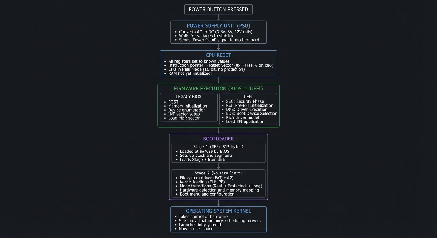
When you press the power button, something magical happens. Within nanoseconds, electricity flows, the CPU awakens at a hardcoded address, and a chain of software begins executing—each link trusting the previous one. This chain is the boot process, and the bootloader is your first opportunity to take control.
The Hidden Complexity Everyone Ignores
Most programmers never think about booting. They press power, wait a few seconds, and their OS appears. But consider:
- Every security vulnerability at boot level is catastrophic: Rootkits, bootkits, and firmware malware can hide from all OS-level security
- Cloud computing runs on this: Every EC2 instance, every container host boots—understanding this is understanding infrastructure
- Embedded systems are everywhere: Your car’s ECU, your router, your smart TV—all boot through code someone wrote
- Recovery depends on it: When Windows won’t start, understanding boot is the difference between fixing it and reinstalling
The boot process is the root of trust for the entire system. Understand it, and you understand computing at its most fundamental level.
The Complete Boot Sequence Visualized
    ┌─────────────────────────────────────────────────────────────────────────┐
    │                           POWER BUTTON PRESSED                           │
    └─────────────────────────────────────────────────────────────────────────┘
                                        │
                                        ▼
    ┌─────────────────────────────────────────────────────────────────────────┐
    │                         POWER SUPPLY UNIT (PSU)                          │
    │  • Converts AC to DC (3.3V, 5V, 12V rails)                              │
    │  • Waits for voltages to stabilize                                       │
    │  • Sends "Power Good" signal to motherboard                             │
    └─────────────────────────────────────────────────────────────────────────┘
                                        │
                                        ▼
    ┌─────────────────────────────────────────────────────────────────────────┐
    │                             CPU RESET                                    │
    │  • All registers set to known values                                    │
    │  • Instruction pointer → Reset Vector (0xFFFFFFF0 on x86)               │
    │  • CPU in Real Mode (16-bit, no protection)                             │
    │  • RAM not yet initialized!                                             │
    └─────────────────────────────────────────────────────────────────────────┘
                                        │
                                        ▼
    ┌─────────────────────────────────────────────────────────────────────────┐
    │                    FIRMWARE EXECUTION (BIOS or UEFI)                     │
    │                                                                          │
    │  ┌────────────────────────┐    ┌────────────────────────────────────┐   │
    │  │     LEGACY BIOS        │    │            UEFI                     │   │
    │  ├────────────────────────┤    ├────────────────────────────────────┤   │
    │  │ • POST (Power-On Self  │    │ • SEC: Security Phase              │   │
    │  │   Test)                │    │ • PEI: Pre-EFI Initialization      │   │
    │  │ • Memory initialization│    │ • DXE: Driver Execution            │   │
    │  │ • Device enumeration   │    │ • BDS: Boot Device Selection       │   │
    │  │ • INT vector setup     │    │ • Rich driver model                │   │
    │  │ • Load MBR sector      │    │ • Load EFI application             │   │
    │  └────────────────────────┘    └────────────────────────────────────┘   │
    └─────────────────────────────────────────────────────────────────────────┘
                                        │
                                        ▼
    ┌─────────────────────────────────────────────────────────────────────────┐
    │                           BOOTLOADER                                     │
    │                                                                          │
    │  ┌─────────────────────────────────────────────────────────────────┐    │
    │  │ Stage 1 (MBR: 512 bytes)                                         │    │
    │  │ • Loaded at 0x7C00 by BIOS                                       │    │
    │  │ • Sets up stack and segments                                     │    │
    │  │ • Loads Stage 2 from disk                                        │    │
    │  └─────────────────────────────────────────────────────────────────┘    │
    │                              │                                           │
    │                              ▼                                           │
    │  ┌─────────────────────────────────────────────────────────────────┐    │
    │  │ Stage 2 (No size limit)                                          │    │
    │  │ • Filesystem driver (FAT, ext2, etc.)                            │    │
    │  │ • Kernel loading and parsing (ELF, PE)                           │    │
    │  │ • Mode transitions (Real → Protected → Long)                     │    │
    │  │ • Hardware detection and memory mapping                          │    │
    │  │ • Boot menu and configuration                                    │    │
    │  └─────────────────────────────────────────────────────────────────┘    │
    └─────────────────────────────────────────────────────────────────────────┘
                                        │
                                        ▼
    ┌─────────────────────────────────────────────────────────────────────────┐
    │                         OPERATING SYSTEM KERNEL                          │
    │  • Takes control of hardware                                            │
    │  • Sets up virtual memory, scheduling, drivers                          │
    │  • Launches init/systemd                                                │
    │  • You're now in user space                                             │
    └─────────────────────────────────────────────────────────────────────────┘
x86 CPU Modes: The Journey Through Privilege
Understanding CPU modes is fundamental to bootloader development. The x86 architecture has evolved through multiple modes, each with different capabilities and restrictions.
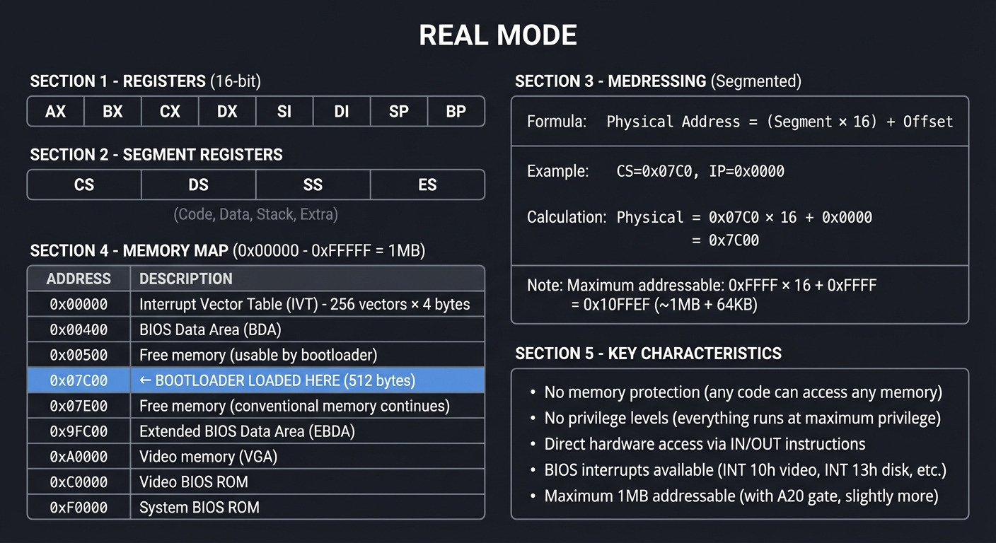
Real Mode (16-bit): Where It All Begins
When an x86 CPU powers on, it awakens in Real Mode—a compatibility mode that behaves like the original 8086 from 1978.
┌─────────────────────────────────────────────────────────────────────────────┐
│                              REAL MODE                                       │
├─────────────────────────────────────────────────────────────────────────────┤
│                                                                              │
│   REGISTERS (16-bit):                                                        │
│   ┌──────┐ ┌──────┐ ┌──────┐ ┌──────┐ ┌──────┐ ┌──────┐ ┌──────┐ ┌──────┐  │
│   │  AX  │ │  BX  │ │  CX  │ │  DX  │ │  SI  │ │  DI  │ │  SP  │ │  BP  │  │
│   └──────┘ └──────┘ └──────┘ └──────┘ └──────┘ └──────┘ └──────┘ └──────┘  │
│                                                                              │
│   SEGMENT REGISTERS:                                                         │
│   ┌──────┐ ┌──────┐ ┌──────┐ ┌──────┐                                       │
│   │  CS  │ │  DS  │ │  SS  │ │  ES  │  (Code, Data, Stack, Extra)           │
│   └──────┘ └──────┘ └──────┘ └──────┘                                       │
│                                                                              │
│   MEMORY ADDRESSING (Segmented):                                             │
│   ┌────────────────────────────────────────────────────────────────────┐    │
│   │ Physical Address = (Segment × 16) + Offset                          │    │
│   │                                                                      │    │
│   │ Example: CS=0x07C0, IP=0x0000                                        │    │
│   │          Physical = 0x07C0 × 16 + 0x0000 = 0x7C00                   │    │
│   │                                                                      │    │
│   │ Maximum addressable: 0xFFFF × 16 + 0xFFFF = 0x10FFEF (~1MB + 64KB)  │    │
│   └────────────────────────────────────────────────────────────────────┘    │
│                                                                              │
│   MEMORY MAP (0x00000 - 0xFFFFF = 1MB):                                     │
│   ┌─────────────┬────────────────────────────────────────────────────────┐  │
│   │ 0x00000     │ Interrupt Vector Table (IVT) - 256 vectors × 4 bytes   │  │
│   ├─────────────┼────────────────────────────────────────────────────────┤  │
│   │ 0x00400     │ BIOS Data Area (BDA)                                   │  │
│   ├─────────────┼────────────────────────────────────────────────────────┤  │
│   │ 0x00500     │ Free memory (usable by bootloader)                     │  │
│   ├─────────────┼────────────────────────────────────────────────────────┤  │
│   │ 0x07C00     │ ← BOOTLOADER LOADED HERE (512 bytes)                   │  │
│   ├─────────────┼────────────────────────────────────────────────────────┤  │
│   │ 0x07E00     │ Free memory (conventional memory continues)            │  │
│   ├─────────────┼────────────────────────────────────────────────────────┤  │
│   │ 0x9FC00     │ Extended BIOS Data Area (EBDA)                         │  │
│   ├─────────────┼────────────────────────────────────────────────────────┤  │
│   │ 0xA0000     │ Video memory (VGA)                                     │  │
│   ├─────────────┼────────────────────────────────────────────────────────┤  │
│   │ 0xC0000     │ Video BIOS ROM                                         │  │
│   ├─────────────┼────────────────────────────────────────────────────────┤  │
│   │ 0xF0000     │ System BIOS ROM                                        │  │
│   └─────────────┴────────────────────────────────────────────────────────┘  │
│                                                                              │
│   KEY CHARACTERISTICS:                                                       │
│   • No memory protection (any code can access any memory)                   │
│   • No privilege levels (everything runs at maximum privilege)              │
│   • Direct hardware access via IN/OUT instructions                          │
│   • BIOS interrupts available (INT 10h video, INT 13h disk, etc.)          │
│   • Maximum 1MB addressable (with A20 gate, slightly more)                 │
│                                                                              │
└─────────────────────────────────────────────────────────────────────────────┘
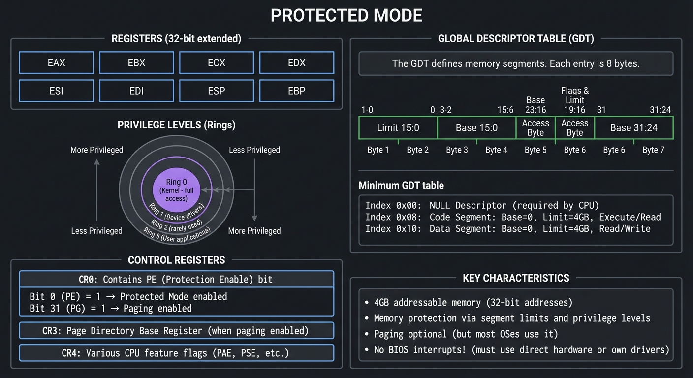
Protected Mode (32-bit): The Modern Operating Mode
Protected Mode was introduced with the 80286 (1982) and fully realized in the 80386 (1985). It provides memory protection, privilege levels, and access to more memory.
┌─────────────────────────────────────────────────────────────────────────────┐
│                            PROTECTED MODE                                    │
├─────────────────────────────────────────────────────────────────────────────┤
│                                                                              │
│   REGISTERS (32-bit extended):                                               │
│   ┌──────────┐ ┌──────────┐ ┌──────────┐ ┌──────────┐                       │
│   │   EAX    │ │   EBX    │ │   ECX    │ │   EDX    │                       │
│   └──────────┘ └──────────┘ └──────────┘ └──────────┘                       │
│   ┌──────────┐ ┌──────────┐ ┌──────────┐ ┌──────────┐                       │
│   │   ESI    │ │   EDI    │ │   ESP    │ │   EBP    │                       │
│   └──────────┘ └──────────┘ └──────────┘ └──────────┘                       │
│                                                                              │
│   GLOBAL DESCRIPTOR TABLE (GDT):                                             │
│   ┌────────────────────────────────────────────────────────────────────┐    │
│   │ The GDT defines memory segments. Each entry is 8 bytes:             │    │
│   │                                                                      │    │
│   │ ┌───────────────────────────────────────────────────────────────┐   │    │
│   │ │ Byte 7  │ Byte 6  │ Byte 5  │ Byte 4  │ Bytes 3-2 │ Bytes 1-0│   │    │
│   │ ├─────────┼─────────┼─────────┼─────────┼───────────┼──────────┤   │    │
│   │ │ Base    │ Flags & │ Access  │ Base    │ Base      │ Limit    │   │    │
│   │ │ 31:24   │ Limit   │ Byte    │ 23:16   │ 15:0      │ 15:0     │   │    │
│   │ │         │ 19:16   │         │         │           │          │   │    │
│   │ └─────────┴─────────┴─────────┴─────────┴───────────┴──────────┘   │    │
│   │                                                                      │    │
│   │ Minimum GDT for Protected Mode:                                      │    │
│   │ ┌────────┬────────────────────────────────────────────────────────┐ │    │
│   │ │ Index  │ Descriptor                                              │ │    │
│   │ ├────────┼────────────────────────────────────────────────────────┤ │    │
│   │ │ 0x00   │ NULL Descriptor (required by CPU)                      │ │    │
│   │ │ 0x08   │ Code Segment: Base=0, Limit=4GB, Execute/Read          │ │    │
│   │ │ 0x10   │ Data Segment: Base=0, Limit=4GB, Read/Write            │ │    │
│   │ └────────┴────────────────────────────────────────────────────────┘ │    │
│   └────────────────────────────────────────────────────────────────────┘    │
│                                                                              │
│   PRIVILEGE LEVELS (Rings):                                                  │
│   ┌─────────────────────────────────────────────────────────────────────┐   │
│   │                         ┌─────────────┐                              │   │
│   │                         │   Ring 0    │ ← Kernel (full access)       │   │
│   │                    ┌────┴─────────────┴────┐                         │   │
│   │                    │       Ring 1          │ ← Device drivers        │   │
│   │               ┌────┴───────────────────────┴────┐                    │   │
│   │               │           Ring 2                │ ← (rarely used)    │   │
│   │          ┌────┴─────────────────────────────────┴────┐               │   │
│   │          │               Ring 3                      │ ← User apps   │   │
│   │          └───────────────────────────────────────────┘               │   │
│   └─────────────────────────────────────────────────────────────────────┘   │
│                                                                              │
│   CONTROL REGISTERS:                                                         │
│   ┌──────────────────────────────────────────────────────────────────────┐  │
│   │ CR0: Contains PE (Protection Enable) bit                              │  │
│   │      Bit 0 (PE) = 1 → Protected Mode enabled                         │  │
│   │      Bit 31 (PG) = 1 → Paging enabled                                │  │
│   │                                                                        │  │
│   │ CR3: Page Directory Base Register (when paging enabled)               │  │
│   │                                                                        │  │
│   │ CR4: Various CPU feature flags (PAE, PSE, etc.)                       │  │
│   └──────────────────────────────────────────────────────────────────────┘  │
│                                                                              │
│   KEY CHARACTERISTICS:                                                       │
│   • 4GB addressable memory (32-bit addresses)                               │
│   • Memory protection via segment limits and privilege levels               │
│   • Paging optional (but most OSes use it)                                 │
│   • No BIOS interrupts! (must use direct hardware or own drivers)          │
│                                                                              │
└─────────────────────────────────────────────────────────────────────────────┘
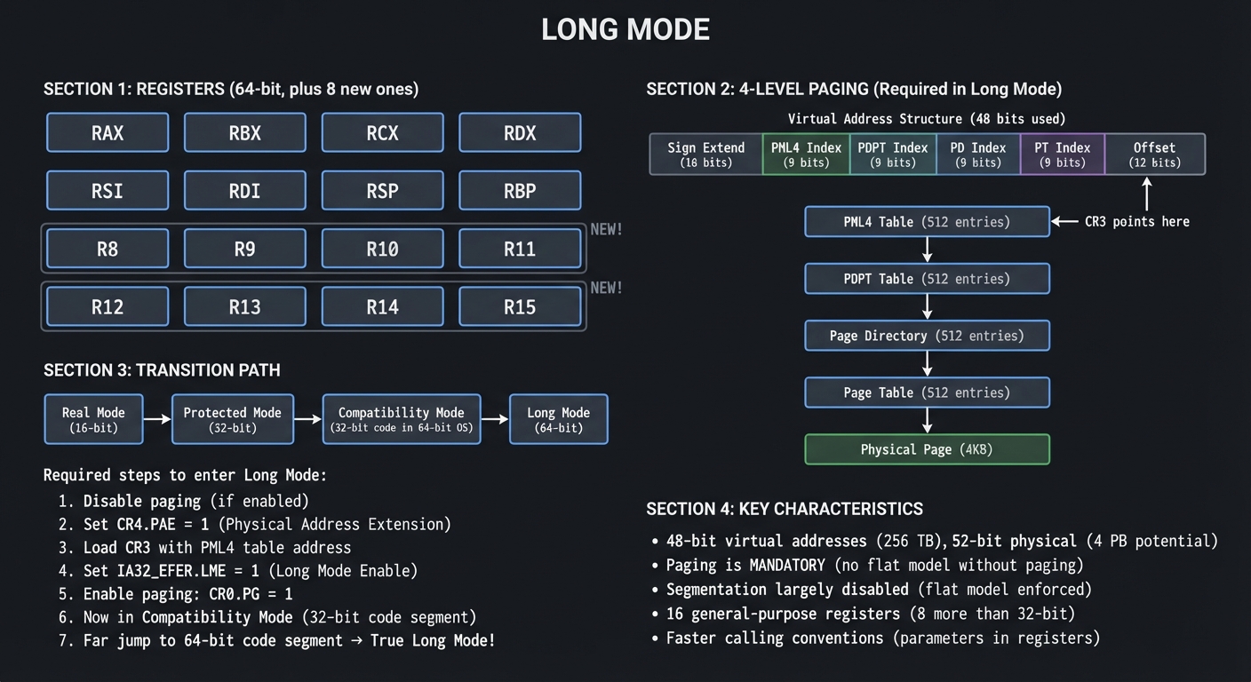
Long Mode (64-bit): The Modern 64-bit Mode
Long Mode, introduced with AMD64/x86-64, provides 64-bit operation and vastly larger address spaces.
┌─────────────────────────────────────────────────────────────────────────────┐
│                              LONG MODE                                       │
├─────────────────────────────────────────────────────────────────────────────┤
│                                                                              │
│   REGISTERS (64-bit, plus 8 new ones):                                       │
│   ┌────────────┐ ┌────────────┐ ┌────────────┐ ┌────────────┐               │
│   │    RAX     │ │    RBX     │ │    RCX     │ │    RDX     │               │
│   └────────────┘ └────────────┘ └────────────┘ └────────────┘               │
│   ┌────────────┐ ┌────────────┐ ┌────────────┐ ┌────────────┐               │
│   │    RSI     │ │    RDI     │ │    RSP     │ │    RBP     │               │
│   └────────────┘ └────────────┘ └────────────┘ └────────────┘               │
│   ┌────────────┐ ┌────────────┐ ┌────────────┐ ┌────────────┐               │
│   │    R8      │ │    R9      │ │    R10     │ │    R11     │  ← NEW!       │
│   └────────────┘ └────────────┘ └────────────┘ └────────────┘               │
│   ┌────────────┐ ┌────────────┐ ┌────────────┐ ┌────────────┐               │
│   │    R12     │ │    R13     │ │    R14     │ │    R15     │  ← NEW!       │
│   └────────────┘ └────────────┘ └────────────┘ └────────────┘               │
│                                                                              │
│   4-LEVEL PAGING (Required in Long Mode):                                    │
│   ┌──────────────────────────────────────────────────────────────────────┐  │
│   │                                                                        │  │
│   │  Virtual Address (48 bits used):                                       │  │
│   │  ┌────────┬─────────┬─────────┬─────────┬─────────┬──────────────┐    │  │
│   │  │ Sign   │ PML4    │ PDPT    │ PD      │ PT      │ Offset       │    │  │
│   │  │ Extend │ Index   │ Index   │ Index   │ Index   │ (12 bits)    │    │  │
│   │  │(16 bit)│ (9 bit) │ (9 bit) │ (9 bit) │ (9 bit) │              │    │  │
│   │  └────────┴────┬────┴────┬────┴────┬────┴────┬────┴──────────────┘    │  │
│   │                │         │         │         │                         │  │
│   │                ▼         │         │         │                         │  │
│   │  ┌─────────────────┐    │         │         │                         │  │
│   │  │ PML4 Table      │    │         │         │                         │  │
│   │  │ (512 entries)   │────┘         │         │                         │  │
│   │  │ CR3 points here │              │         │                         │  │
│   │  └───────┬─────────┘              │         │                         │  │
│   │          │                        ▼         │                         │  │
│   │          │         ┌─────────────────┐      │                         │  │
│   │          └────────→│ PDPT Table      │      │                         │  │
│   │                    │ (512 entries)   │──────┘                         │  │
│   │                    └───────┬─────────┘                                │  │
│   │                            │                 ▼                        │  │
│   │                            │  ┌─────────────────┐                     │  │
│   │                            └─→│ Page Directory  │                     │  │
│   │                               │ (512 entries)   │─────────────────┐   │  │
│   │                               └───────┬─────────┘                 │   │  │
│   │                                       │                           ▼   │  │
│   │                                       │        ┌─────────────────┐    │  │
│   │                                       └───────→│ Page Table      │    │  │
│   │                                                │ (512 entries)   │    │  │
│   │                                                └───────┬─────────┘    │  │
│   │                                                        │              │  │
│   │                                                        ▼              │  │
│   │                                           Physical Page (4KB)         │  │
│   │                                                                        │  │
│   └──────────────────────────────────────────────────────────────────────┘  │
│                                                                              │
│   TRANSITION PATH:                                                           │
│   ┌──────────────────────────────────────────────────────────────────────┐  │
│   │                                                                        │  │
│   │  Real Mode ──┬──→ Protected Mode ──→ Compatibility Mode ──→ Long Mode │  │
│   │              │         │                    │                          │  │
│   │    (16-bit)  │    (32-bit)          (32-bit code in         (64-bit)  │  │
│   │              │                       64-bit OS)                        │  │
│   │              │                                                         │  │
│   │  Required steps to enter Long Mode:                                    │  │
│   │  1. Disable paging (if enabled)                                        │  │
│   │  2. Set CR4.PAE = 1 (Physical Address Extension)                       │  │
│   │  3. Load CR3 with PML4 table address                                   │  │
│   │  4. Set IA32_EFER.LME = 1 (Long Mode Enable)                          │  │
│   │  5. Enable paging: CR0.PG = 1                                          │  │
│   │  6. Now in Compatibility Mode (32-bit code segment)                    │  │
│   │  7. Far jump to 64-bit code segment → True Long Mode!                  │  │
│   │                                                                        │  │
│   └──────────────────────────────────────────────────────────────────────┘  │
│                                                                              │
│   KEY CHARACTERISTICS:                                                       │
│   • 48-bit virtual addresses (256 TB), 52-bit physical (4 PB potential)    │
│   • Paging is MANDATORY (no flat model without paging)                      │
│   • Segmentation largely disabled (flat model enforced)                     │
│   • 16 general-purpose registers (8 more than 32-bit)                       │
│   • Faster calling conventions (parameters in registers)                    │
│                                                                              │
└─────────────────────────────────────────────────────────────────────────────┘
BIOS vs UEFI: Two Different Worlds
Legacy BIOS: The Original Way
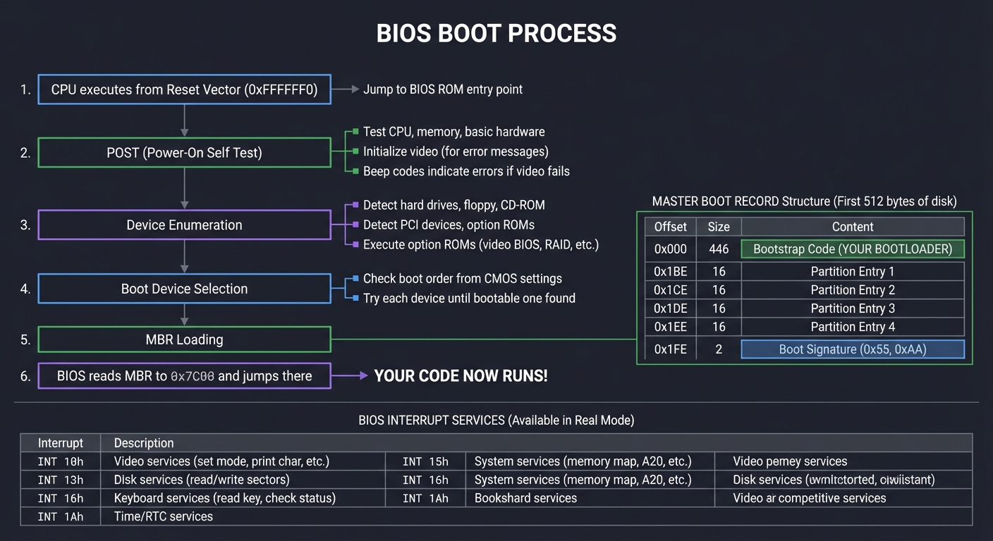
BIOS (Basic Input/Output System) dates back to the original IBM PC (1981). It’s simple, limited, but well-understood.
┌─────────────────────────────────────────────────────────────────────────────┐
│                            BIOS BOOT PROCESS                                 │
├─────────────────────────────────────────────────────────────────────────────┤
│                                                                              │
│  1. CPU executes from Reset Vector (0xFFFFFFF0)                             │
│     └─→ Jump to BIOS ROM entry point                                        │
│                                                                              │
│  2. POST (Power-On Self Test)                                                │
│     ├─→ Test CPU, memory, basic hardware                                    │
│     ├─→ Initialize video (for error messages)                               │
│     └─→ Beep codes indicate errors if video fails                           │
│                                                                              │
│  3. Device Enumeration                                                       │
│     ├─→ Detect hard drives, floppy, CD-ROM                                  │
│     ├─→ Detect PCI devices, option ROMs                                     │
│     └─→ Execute option ROMs (video BIOS, RAID, etc.)                        │
│                                                                              │
│  4. Boot Device Selection                                                    │
│     ├─→ Check boot order from CMOS settings                                 │
│     └─→ Try each device until bootable one found                            │
│                                                                              │
│  5. MBR Loading                                                              │
│     ┌─────────────────────────────────────────────────────────────────┐     │
│     │                    MASTER BOOT RECORD                            │     │
│     │                    (First 512 bytes of disk)                     │     │
│     ├─────────────────────────────────────────────────────────────────┤     │
│     │ Offset │ Size  │ Content                                         │     │
│     ├────────┼───────┼─────────────────────────────────────────────────┤     │
│     │ 0x000  │ 446   │ Bootstrap Code (YOUR BOOTLOADER)                │     │
│     │ 0x1BE  │ 16    │ Partition Entry 1                               │     │
│     │ 0x1CE  │ 16    │ Partition Entry 2                               │     │
│     │ 0x1DE  │ 16    │ Partition Entry 3                               │     │
│     │ 0x1EE  │ 16    │ Partition Entry 4                               │     │
│     │ 0x1FE  │ 2     │ Boot Signature (0x55, 0xAA)                     │     │
│     └────────┴───────┴─────────────────────────────────────────────────┘     │
│                                                                              │
│  6. BIOS reads MBR to 0x7C00 and jumps there                                │
│     └─→ YOUR CODE NOW RUNS!                                                 │
│                                                                              │
│  BIOS INTERRUPT SERVICES (Available in Real Mode):                          │
│  ┌──────────┬───────────────────────────────────────────────────────────┐   │
│  │ INT 10h  │ Video services (set mode, print char, etc.)               │   │
│  │ INT 13h  │ Disk services (read/write sectors)                        │   │
│  │ INT 15h  │ System services (memory map, A20, etc.)                   │   │
│  │ INT 16h  │ Keyboard services (read key, check status)                │   │
│  │ INT 1Ah  │ Time/RTC services                                         │   │
│  └──────────┴───────────────────────────────────────────────────────────┘   │
│                                                                              │
└─────────────────────────────────────────────────────────────────────────────┘
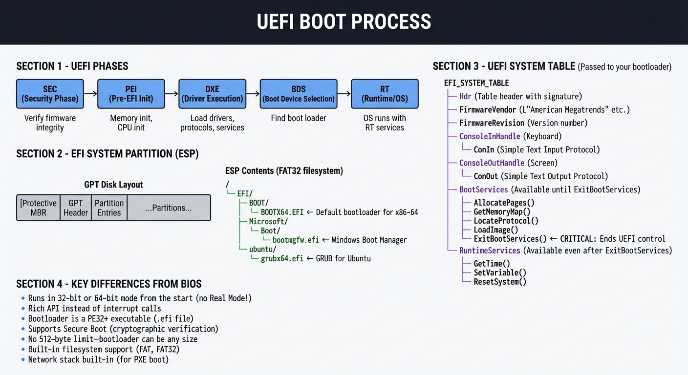
UEFI: The Modern Standard
UEFI (Unified Extensible Firmware Interface) replaces BIOS with a modern, extensible architecture.
┌─────────────────────────────────────────────────────────────────────────────┐
│                            UEFI BOOT PROCESS                                 │
├─────────────────────────────────────────────────────────────────────────────┤
│                                                                              │
│  UEFI PHASES:                                                                │
│  ┌────────────────────────────────────────────────────────────────────────┐ │
│  │                                                                          │ │
│  │  ┌─────────┐    ┌─────────┐    ┌─────────┐    ┌─────────┐    ┌───────┐ │ │
│  │  │   SEC   │───→│   PEI   │───→│   DXE   │───→│   BDS   │───→│  RT   │ │ │
│  │  │Security │    │Pre-EFI  │    │ Driver  │    │ Boot    │    │Runtime│ │ │
│  │  │  Phase  │    │  Init   │    │Execution│    │ Device  │    │ (OS)  │ │ │
│  │  └─────────┘    └─────────┘    └─────────┘    │Selection│    └───────┘ │ │
│  │       │              │              │         └─────────┘        │     │ │
│  │       │              │              │              │             │     │ │
│  │  Verify        Memory init    Load drivers   Find boot      OS runs  │ │
│  │  firmware      CPU init       protocols      loader         with RT  │ │
│  │  integrity                    services                     services  │ │
│  │                                                                          │ │
│  └────────────────────────────────────────────────────────────────────────┘ │
│                                                                              │
│  EFI SYSTEM PARTITION (ESP):                                                 │
│  ┌────────────────────────────────────────────────────────────────────────┐ │
│  │                                                                          │ │
│  │  GPT Disk Layout:                                                        │ │
│  │  ┌───────────────────────────────────────────────────────────────────┐  │ │
│  │  │ Protective MBR │ GPT Header │ Partition Entries │ ...Partitions... │  │ │
│  │  └───────────────────────────────────────────────────────────────────┘  │ │
│  │                                                                          │ │
│  │  ESP Contents (FAT32 filesystem):                                        │ │
│  │  /                                                                       │ │
│  │  └── EFI/                                                                │ │
│  │      ├── BOOT/                                                           │ │
│  │      │   └── BOOTX64.EFI  ← Default bootloader for x86-64               │ │
│  │      ├── Microsoft/                                                      │ │
│  │      │   └── Boot/                                                       │ │
│  │      │       └── bootmgfw.efi  ← Windows Boot Manager                   │ │
│  │      └── ubuntu/                                                         │ │
│  │          └── grubx64.efi  ← GRUB for Ubuntu                             │ │
│  │                                                                          │ │
│  └────────────────────────────────────────────────────────────────────────┘ │
│                                                                              │
│  UEFI SYSTEM TABLE (Passed to your bootloader):                             │
│  ┌────────────────────────────────────────────────────────────────────────┐ │
│  │                                                                          │ │
│  │  EFI_SYSTEM_TABLE                                                        │ │
│  │  ├── Hdr                   (Table header with signature)                │ │
│  │  ├── FirmwareVendor        (L"American Megatrends" etc.)                │ │
│  │  ├── FirmwareRevision      (Version number)                              │ │
│  │  ├── ConsoleInHandle       (Keyboard)                                    │ │
│  │  ├── ConIn                 (Simple Text Input Protocol)                  │ │
│  │  ├── ConsoleOutHandle      (Screen)                                      │ │
│  │  ├── ConOut                (Simple Text Output Protocol)                 │ │
│  │  ├── BootServices          (Available until ExitBootServices)            │ │
│  │  │   ├── AllocatePages()                                                 │ │
│  │  │   ├── GetMemoryMap()                                                  │ │
│  │  │   ├── LocateProtocol()                                                │ │
│  │  │   ├── LoadImage()                                                     │ │
│  │  │   └── ExitBootServices()  ← CRITICAL: Ends UEFI control             │ │
│  │  └── RuntimeServices       (Available even after ExitBootServices)       │ │
│  │      ├── GetTime()                                                       │ │
│  │      ├── SetVariable()                                                   │ │
│  │      └── ResetSystem()                                                   │ │
│  │                                                                          │ │
│  └────────────────────────────────────────────────────────────────────────┘ │
│                                                                              │
│  KEY DIFFERENCES FROM BIOS:                                                  │
│  • Runs in 32-bit or 64-bit mode from the start (no Real Mode!)            │
│  • Rich API instead of interrupt calls                                      │
│  • Bootloader is a PE32+ executable (.efi file)                             │
│  • Supports Secure Boot (cryptographic verification)                        │
│  • No 512-byte limit—bootloader can be any size                            │
│  • Built-in filesystem support (FAT, FAT32)                                 │
│  • Network stack built-in (for PXE boot)                                    │
│                                                                              │
└─────────────────────────────────────────────────────────────────────────────┘
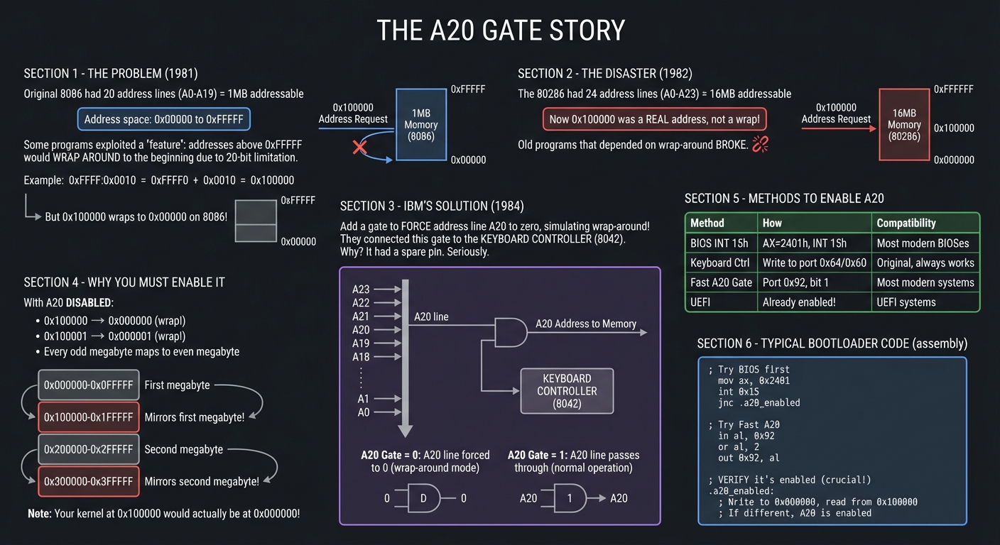
The A20 Gate: A Historical Absurdity You Must Handle
One of the most bizarre aspects of x86 boot programming is the A20 line. Understanding why it exists helps you appreciate x86’s backwards-compatibility obsession.
┌─────────────────────────────────────────────────────────────────────────────┐
│                            THE A20 GATE STORY                                │
├─────────────────────────────────────────────────────────────────────────────┤
│                                                                              │
│  THE PROBLEM (1981):                                                         │
│  The original 8086 had 20 address lines (A0-A19) = 1MB addressable          │
│                                                                              │
│  Address space: 0x00000 to 0xFFFFF                                          │
│                                                                              │
│  Some programs exploited a "feature": addresses above 0xFFFFF would         │
│  WRAP AROUND to the beginning due to 20-bit limitation.                     │
│                                                                              │
│  Example: 0xFFFF:0x0010 = 0xFFFF0 + 0x0010 = 0x100000                       │
│           But 0x100000 wraps to 0x00000 on 8086!                            │
│                                                                              │
│  ────────────────────────────────────────────────────────────────────────   │
│                                                                              │
│  THE DISASTER (1982):                                                        │
│  The 80286 had 24 address lines (A0-A23) = 16MB addressable                 │
│  Now 0x100000 was a REAL address, not a wrap!                               │
│                                                                              │
│  Old programs that depended on wrap-around BROKE.                           │
│                                                                              │
│  ────────────────────────────────────────────────────────────────────────   │
│                                                                              │
│  IBM'S "SOLUTION" (1984):                                                    │
│  Add a gate to FORCE address line A20 to zero, simulating wrap-around!      │
│                                                                              │
│  They connected this gate to... the KEYBOARD CONTROLLER (8042).             │
│  Why? It had a spare pin. Seriously.                                        │
│                                                                              │
│  ┌─────────────────────────────────────────────────────────────────────┐    │
│  │                                                                       │    │
│  │    Address Lines:  A23 A22 A21 A20 A19 A18 ... A1 A0                 │    │
│  │                     │   │   │   │                                    │    │
│  │                     │   │   │   └─── A20 Gate ─── Keyboard Controller│    │
│  │                     │   │   │            │                           │    │
│  │                     │   │   │        ┌───┴───┐                       │    │
│  │                     │   │   │        │ AND   │                       │    │
│  │                     │   │   │        │ Gate  │                       │    │
│  │                     │   │   │        └───┬───┘                       │    │
│  │                     │   │   │            │                           │    │
│  │                     │   │   │            ▼                           │    │
│  │                     │   │   └────────► Memory                        │    │
│  │                                                                       │    │
│  │    A20 Gate = 0: A20 line forced to 0 (wrap-around mode)             │    │
│  │    A20 Gate = 1: A20 line passes through (normal operation)           │    │
│  │                                                                       │    │
│  └─────────────────────────────────────────────────────────────────────┘    │
│                                                                              │
│  WHY YOU MUST ENABLE IT:                                                     │
│  ┌─────────────────────────────────────────────────────────────────────┐    │
│  │                                                                       │    │
│  │  With A20 DISABLED:                                                   │    │
│  │  • 0x100000 → 0x000000 (wrap!)                                       │    │
│  │  • 0x100001 → 0x000001 (wrap!)                                       │    │
│  │  • Every odd megabyte maps to even megabyte                          │    │
│  │                                                                       │    │
│  │  Memory appears like this:                                            │    │
│  │  0x000000 ─┬─ First megabyte                                         │    │
│  │  0x0FFFFF ─┘                                                          │    │
│  │  0x100000 ─┬─ Mirrors first megabyte!                                │    │
│  │  0x1FFFFF ─┘                                                          │    │
│  │  0x200000 ─┬─ Second megabyte                                        │    │
│  │  0x2FFFFF ─┘                                                          │    │
│  │  0x300000 ─┬─ Mirrors second megabyte!                               │    │
│  │  ...                                                                  │    │
│  │                                                                       │    │
│  │  Your kernel at 0x100000 would actually be at 0x000000!              │    │
│  │                                                                       │    │
│  └─────────────────────────────────────────────────────────────────────┘    │
│                                                                              │
│  METHODS TO ENABLE A20:                                                      │
│  ┌────────────────────────────────────────────────────────────────────────┐ │
│  │ Method         │ How                        │ Compatibility            │ │
│  ├────────────────┼────────────────────────────┼──────────────────────────┤ │
│  │ BIOS INT 15h   │ AX=2401h, INT 15h          │ Most modern BIOSes      │ │
│  │ Keyboard Ctrl  │ Write to port 0x64/0x60    │ Original, always works  │ │
│  │ Fast A20 Gate  │ Port 0x92, bit 1           │ Most modern systems     │ │
│  │ UEFI           │ Already enabled!           │ UEFI systems            │ │
│  └────────────────┴────────────────────────────┴──────────────────────────┘ │
│                                                                              │
│  TYPICAL BOOTLOADER CODE:                                                    │
│  ┌─────────────────────────────────────────────────────────────────────┐    │
│  │  ; Try BIOS first                                                    │    │
│  │  mov ax, 0x2401                                                      │    │
│  │  int 0x15                                                            │    │
│  │  jnc .a20_enabled                                                    │    │
│  │                                                                       │    │
│  │  ; Try Fast A20                                                       │    │
│  │  in al, 0x92                                                          │    │
│  │  or al, 2                                                             │    │
│  │  out 0x92, al                                                         │    │
│  │                                                                       │    │
│  │  ; Try keyboard controller (complex, but always works)               │    │
│  │  ; ... wait for 8042, write command, etc.                            │    │
│  │                                                                       │    │
│  │  ; VERIFY it's enabled (crucial!)                                    │    │
│  │  .a20_enabled:                                                        │    │
│  │  ; Write to 0x000000, read from 0x100000                             │    │
│  │  ; If different, A20 is enabled                                      │    │
│  └─────────────────────────────────────────────────────────────────────┘    │
│                                                                              │
└─────────────────────────────────────────────────────────────────────────────┘
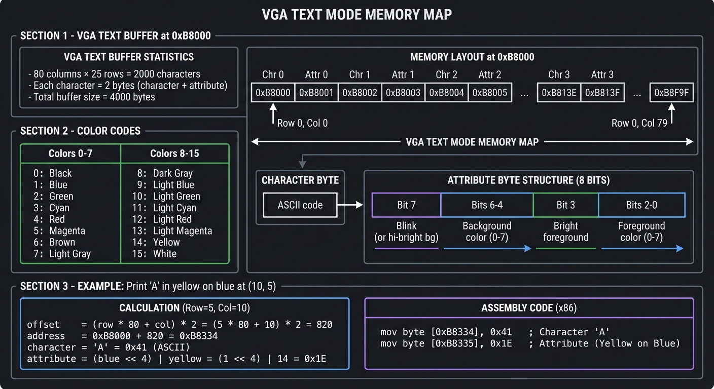
Memory-Mapped I/O and VGA
Once in Protected Mode, BIOS interrupts no longer work. You must access hardware directly. VGA text mode is the classic example.
┌─────────────────────────────────────────────────────────────────────────────┐
│                       VGA TEXT MODE MEMORY MAP                               │
├─────────────────────────────────────────────────────────────────────────────┤
│                                                                              │
│  VGA TEXT BUFFER at 0xB8000:                                                 │
│  ┌─────────────────────────────────────────────────────────────────────┐    │
│  │                                                                       │    │
│  │  80 columns × 25 rows = 2000 characters                              │    │
│  │  Each character = 2 bytes (character + attribute)                    │    │
│  │  Total buffer size = 4000 bytes                                      │    │
│  │                                                                       │    │
│  │  Memory layout:                                                       │    │
│  │  0xB8000 ┌────┬────┬────┬────┬────┬────┬────┬────┬─...─┐             │    │
│  │          │Chr │Attr│Chr │Attr│Chr │Attr│Chr │Attr│     │             │    │
│  │          │ 0  │ 0  │ 1  │ 1  │ 2  │ 2  │ 3  │ 3  │     │             │    │
│  │          └────┴────┴────┴────┴────┴────┴────┴────┴─...─┘             │    │
│  │          Row 0, Col 0 ─────────────────────────► Row 0, Col 79       │    │
│  │                                                                       │    │
│  │  Character byte: ASCII code                                           │    │
│  │  Attribute byte:                                                      │    │
│  │  ┌─────────────────────────────────────────────────────────┐         │    │
│  │  │ Bit 7   │ Bits 6-4      │ Bit 3   │ Bits 2-0           │         │    │
│  │  ├─────────┼───────────────┼─────────┼────────────────────┤         │    │
│  │  │ Blink   │ Background    │ Bright  │ Foreground         │         │    │
│  │  │ (or hi- │ color (0-7)   │ fore-   │ color (0-7)        │         │    │
│  │  │ bright  │               │ ground  │                    │         │    │
│  │  │ bg)     │               │         │                    │         │    │
│  │  └─────────┴───────────────┴─────────┴────────────────────┘         │    │
│  │                                                                       │    │
│  │  COLOR CODES:                                                         │    │
│  │  ┌────┬─────────────┬────┬──────────────────┐                        │    │
│  │  │ 0  │ Black       │ 8  │ Dark Gray        │                        │    │
│  │  │ 1  │ Blue        │ 9  │ Light Blue       │                        │    │
│  │  │ 2  │ Green       │ 10 │ Light Green      │                        │    │
│  │  │ 3  │ Cyan        │ 11 │ Light Cyan       │                        │    │
│  │  │ 4  │ Red         │ 12 │ Light Red        │                        │    │
│  │  │ 5  │ Magenta     │ 13 │ Light Magenta    │                        │    │
│  │  │ 6  │ Brown       │ 14 │ Yellow           │                        │    │
│  │  │ 7  │ Light Gray  │ 15 │ White            │                        │    │
│  │  └────┴─────────────┴────┴──────────────────┘                        │    │
│  │                                                                       │    │
│  │  EXAMPLE: Print 'A' in yellow on blue at (10, 5)                     │    │
│  │  ┌─────────────────────────────────────────────────────────────┐    │    │
│  │  │  offset = (row * 80 + col) * 2 = (5 * 80 + 10) * 2 = 820    │    │    │
│  │  │  address = 0xB8000 + 820 = 0xB8334                          │    │    │
│  │  │  character = 'A' = 0x41                                      │    │    │
│  │  │  attribute = (blue << 4) | yellow = (1 << 4) | 14 = 0x1E    │    │    │
│  │  │                                                               │    │    │
│  │  │  mov byte [0xB8334], 0x41    ; Character                     │    │    │
│  │  │  mov byte [0xB8335], 0x1E    ; Attribute                     │    │    │
│  │  └─────────────────────────────────────────────────────────────┘    │    │
│  │                                                                       │    │
│  └─────────────────────────────────────────────────────────────────────┘    │
│                                                                              │
└─────────────────────────────────────────────────────────────────────────────┘
Concept Summary Table
| Concept Cluster | What You Need to Internalize |
|---|---|
| CPU Reset & Execution Start | When power is applied, the CPU begins at a hardcoded address (reset vector). All state is predictable at this moment. |
| Real Mode | 16-bit mode with 1MB limit, segment:offset addressing, no protection. BIOS services available via interrupts. |
| Protected Mode | 32-bit mode with memory protection via GDT, privilege rings, 4GB addressable. No BIOS interrupts. |
| Long Mode | 64-bit mode requiring paging. 4-level page tables, more registers, modern calling conventions. |
| GDT (Global Descriptor Table) | Defines memory segments with base, limit, and access rights. Required for Protected Mode. |
| Paging | Maps virtual addresses to physical addresses via multi-level page tables. Required for Long Mode. |
| A20 Gate | Historical hack that must be enabled to access memory above 1MB. Multiple enable methods exist. |
| BIOS vs UEFI | BIOS: legacy, Real Mode, interrupts, 512-byte MBR. UEFI: modern, PE executables, rich API, Secure Boot. |
| MBR Structure | First 512 bytes: 446 bytes code, 64 bytes partition table, 2 bytes signature (0xAA55). |
| Memory-Mapped I/O | Hardware registers accessed like memory. VGA at 0xB8000, device registers at fixed addresses. |
| Firmware Services | BIOS provides INT 10h/13h/15h etc. UEFI provides Boot Services and Runtime Services via pointers. |
| Chain Loading | One bootloader loading another. Essential for multi-OS systems. |
Deep Dive Reading by Concept
This section maps each bootloader concept to specific book chapters for deeper understanding.
CPU Modes and Mode Transitions
| Concept | Book | Chapter |
|---|---|---|
| x86 Real Mode fundamentals | Low-Level Programming by Igor Zhirkov | Ch. 3: “Assembly Language” |
| Protected Mode entry | Low-Level Programming by Igor Zhirkov | Ch. 4: “Virtual Memory” |
| Long Mode transition | Low-Level Programming by Igor Zhirkov | Ch. 5: “Compilation Pipeline” |
| x86 execution modes | Computer Systems: A Programmer’s Perspective by Bryant & O’Hallaron | Ch. 3: “Machine-Level Representation” |
| CPU control registers | Intel SDM Volume 3 | Ch. 2: “System Architecture Overview” |
Memory and Segmentation
| Concept | Book | Chapter |
|---|---|---|
| Segment:offset addressing | The Art of Assembly Language, 2nd Ed by Randall Hyde | Ch. 4: “Memory” |
| GDT structure and setup | Operating Systems: Three Easy Pieces by Arpaci-Dusseau | Part II: “Virtualization” |
| Paging fundamentals | Computer Systems: A Programmer’s Perspective by Bryant & O’Hallaron | Ch. 9: “Virtual Memory” |
| x86-64 4-level paging | Low-Level Programming by Igor Zhirkov | Ch. 5: “Compilation Pipeline” |
Firmware and Boot Process
| Concept | Book | Chapter |
|---|---|---|
| BIOS architecture | Beyond BIOS by Vincent Zimmer | Ch. 1-3: “BIOS Background” |
| UEFI fundamentals | Beyond BIOS by Vincent Zimmer | Ch. 4-7: “UEFI Architecture” |
| Boot sequence overview | Operating Systems: Three Easy Pieces by Arpaci-Dusseau | Ch. 2: “Introduction” |
| Option ROMs and PCI | The Secret Life of Programs by Jonathan Steinhart | Ch. 9: “The Operating System” |
Disk and Filesystem Access
| Concept | Book | Chapter |
|---|---|---|
| MBR and disk layout | Practical Binary Analysis by Dennis Andriesse | Ch. 3: “The Binary Format” |
| INT 13h disk services | The Art of Assembly Language, 2nd Ed by Randall Hyde | Ch. 13: “BIOS and DOS Services” |
| FAT filesystem internals | Operating Systems: Three Easy Pieces by Arpaci-Dusseau | Ch. 40: “File System Implementation” |
| GPT and modern partitioning | How Linux Works, 3rd Ed by Brian Ward | Ch. 4: “Disks and Filesystems” |
Low-Level Hardware Access
| Concept | Book | Chapter |
|---|---|---|
| Memory-mapped I/O | Making Embedded Systems, 2nd Ed by Elecia White | Ch. 4: “Inputs and Outputs” |
| VGA programming | Write Great Code, Volume 2, 2nd Ed by Randall Hyde | Ch. 8: “Video Display Systems” |
| Serial port (UART) | Bare Metal C by Steve Oualline | Ch. 6: “Serial I/O” |
| Keyboard controller | The Art of Assembly Language, 2nd Ed by Randall Hyde | Ch. 13: “BIOS and DOS Services” |
Assembly and Bare Metal Programming
| Concept | Book | Chapter |
|---|---|---|
| x86 assembly fundamentals | The Art of 64-Bit Assembly, Volume 1 by Randall Hyde | Ch. 1-4: “Assembly Basics” |
| NASM syntax | Low-Level Programming by Igor Zhirkov | Ch. 3: “Assembly Language” |
| Bare metal C | Bare Metal C by Steve Oualline | Ch. 1-3: “Bare Metal Fundamentals” |
| Linker scripts | Low-Level Programming by Igor Zhirkov | Ch. 6: “Interrupts and System Calls” |
Platform-Specific Topics
| Concept | Book | Chapter |
|---|---|---|
| ARM boot process | Making Embedded Systems, 2nd Ed by Elecia White | Ch. 4: “Inputs and Outputs” |
| Raspberry Pi bare metal | Bare Metal C by Steve Oualline | Ch. 7-8: “Raspberry Pi” |
| U-Boot bootloader | Embedded Linux Primer by Christopher Hallinan | Ch. 7: “Bootloaders” |
| QEMU debugging | The Art of Debugging by Matloff & Salzman | Ch. 1-3: “GDB Basics” |
Quick Start: Your First 48 Hours
Feeling overwhelmed by the concepts? Here’s a focused path to get you booting code within two days.
Day 1: Setup and First Boot (4-6 hours)
Morning: Environment Setup (2 hours)
- Install NASM:
brew install nasm(macOS) orapt install nasm(Linux) - Install QEMU:
brew install qemuorapt install qemu-system-x86 - Test the tools:
nasm -version # Should show NASM version 2.14+ qemu-system-x86_64 --version # Should show QEMU version 6.0+ - Create a workspace directory:
mkdir bootloader-journey && cd bootloader-journey
Afternoon: Project 1 - Hello World Bootloader (2-4 hours)
- Jump straight to Project 1: “The 512-Byte Hello World Bootloader”
- Don’t worry about understanding everything—just follow the implementation hints
- Goal: See “Hello, Bare Metal!” on your screen
- When stuck: Read “The Core Question You’re Answering” section
Evening: Understanding What Happened (1-2 hours)
- Reread the “x86 CPU Modes” section (lines 195-420)
- Study the ASCII diagram of the boot sequence
- Answer these questions in a notebook:
- Where does the BIOS load my code? (Answer: 0x7C00)
- Why is my bootloader exactly 512 bytes? (Answer: MBR sector size)
- What does
INT 10hdo? (Answer: BIOS video service)
Day 2: Memory and Mode Switching (4-6 hours)
Morning: Project 2 - Memory Detective (2-3 hours)
- Complete Project 2: “Memory Map Detective”
- Goal: See the E820 memory map displayed
- Key learning: Not all memory addresses are usable RAM
Afternoon: Read Core Concepts (2 hours)
- Study “BIOS vs UEFI: Two Different Worlds” section
- Read “The A20 Gate: A Historical Absurdity You Must Handle”
- Skim the GDT explanation in Project 3’s prerequisites
Evening: Reflection (1 hour)
- Can you explain to someone (even a rubber duck) what happens when you press the power button?
- Do you understand why we need different CPU modes?
- If yes → Continue to Project 3 tomorrow
- If no → Reread “Why Bootloaders Matter” and the boot sequence diagram
Day 3 and Beyond: Choose Your Path
After the first 48 hours, you have options:
Path A: Sequential Deep Dive (Recommended for beginners)
- Continue Projects 1 → 2 → 3 → 4 → 5 → 6 in order
- Each project builds on the previous one
- Time: 2-3 months, 5-10 hours/week
Path B: UEFI Focus (For modern systems)
- Do Projects 1-2 for context
- Jump to Projects 7-8 (UEFI)
- Return to Projects 3-6 if you need x86 mode details
- Time: 1-2 months, 5-10 hours/week
Path C: ARM/Embedded Focus (For embedded engineers)
- Do Projects 1-2 for concepts
- Jump to Projects 9-10 (Raspberry Pi, U-Boot)
- Time: 1-2 months, 5-10 hours/week
When You Get Stuck (You Will!)
“My bootloader doesn’t boot—just a black screen”
- Check bytes 510-511 with
hexdump -C boot.bin | tail - Should show:
000001f0 ... 55 aa - If not, your padding or signature is wrong
“QEMU closes immediately”
- Missing
-drive format=raw,file=boot.binargument - Or use:
qemu-system-x86_64 -hda boot.bin
“I don’t understand assembly”
- Start with Projects 1-2 anyway
- Assembly makes more sense when you have a goal
- Use the “Hints in Layers” sections
- Reference “Low-Level Programming” Chapter 3 as you go
“This is too hard”
- You’re right. It is hard. This is systems programming.
- But thousands have learned this. You can too.
- Each error message teaches you how computers actually work.
- Use the thinking exercises before coding—they build intuition.
Success Markers
You’re making real progress when:
- ✓ You can boot custom code in QEMU without Googling commands
- ✓ You understand why the boot signature is 0xAA55 (little-endian)
- ✓ You can explain segment:offset addressing to someone
- ✓ You’re comfortable with hexadecimal and binary
- ✓ You know when to use assembly vs. C in bootloader code
Resources for the First Week
Essential reading (in order):
- “Low-Level Programming” by Igor Zhirkov - Chapter 1 (Memory basics)
- OSDev Wiki: Real Mode (15-minute read)
- OSDev Wiki: Babystep1 (Basic bootloader tutorial)
- Ralf Brown’s Interrupt List: INT 10h entries (reference, not full read)
Videos (optional but helpful):
- Search YouTube for “writing a bootloader from scratch”
- Look for videos that show real QEMU output
Community help:
- OSDev.org Forums: Beginner questions welcome
- r/osdev subreddit: Post screenshots of your errors
- Stack Overflow: Tag questions with [bootloader] and [x86]
Projects
Project 1: “The 512-Byte Hello World Bootloader”
| Attribute | Value |
|---|---|
| Language | x86 Assembly (NASM) (alt: FASM, GAS (AT&T syntax), MASM) |
| Difficulty | Intermediate |
| Time | Weekend |
| Coolness | ★★★★☆ Hardcore |
| Portfolio Value | Resume Gold |
What you’ll build: A bootloader that fits in exactly 512 bytes, displays “Hello, Bare Metal!” on screen using BIOS interrupts, and ends with the magic boot signature 0xAA55.
Why it teaches bootloaders: This is THE starting point. You’ll understand why bootloaders are exactly 512 bytes (MBR constraint), how the BIOS loads code at address 0x7C00, and how to use BIOS interrupts (INT 10h) for output before any OS exists. You’re literally writing the first code that runs after the firmware.
Core challenges you’ll face:
- Understanding the boot address (0x7C00) → maps to memory layout at boot
- Writing position-independent or origin-aware code → maps to how code addresses work
- Using BIOS interrupts (INT 10h, INT 13h) → maps to firmware services
- Fitting everything in 512 bytes with 0xAA55 signature → maps to MBR structure
- Creating a bootable disk image → maps to disk layout fundamentals
Key Concepts:
- Reset Vector and Initial Execution: “Low-Level Programming” Chapter 1 - Igor Zhirkov
- x86 Real Mode Segmentation: OSDev Wiki - Real Mode
- BIOS Interrupts: Ralf Brown’s Interrupt List
- MBR Structure: “Computer Systems: A Programmer’s Perspective” Chapter 7 - Bryant & O’Hallaron
Prerequisites: Basic understanding of hexadecimal, willingness to read x86 assembly
Real World Outcome
# After assembling your bootloader
$ nasm -f bin boot.asm -o boot.bin
$ qemu-system-x86_64 -drive format=raw,file=boot.bin

# You'll see in the QEMU window:
Hello, Bare Metal!
_
The cursor blinks on a black screen with your message. You wrote the very first code that ran on this (virtual) machine. No OS, no libraries, just your bytes.
Implementation Hints: Your bootloader must:
- Start with
ORG 0x7C00or set up segments correctly (BIOS loads you here) - Set up segment registers (DS, ES, SS) - they’re undefined at boot!
- Set up a stack (SP register) - you need it for any CALL instructions
- Use
INT 10h, AH=0Eh(teletype output) to print characters one by one - End with
times 510-($-$$) db 0to pad to 510 bytes - Finish with
dw 0xAA55- the magic boot signature
The BIOS checks the last two bytes of the first sector. If they’re not 0x55 0xAA (little-endian: 0xAA55), it won’t boot your code.
Learning milestones:
- Code runs in QEMU → You understand the boot process initiates
- “Hello” appears on screen → You can use BIOS services
- You can modify and reload instantly → You have a development cycle for bare-metal code
The Core Question You’re Answering
“What is the very first code that runs when a computer boots, and how does it work without an operating system?”
This project answers the fundamental question of how a computer transitions from powered-off hardware to running code. You’ll discover:
- How the BIOS/firmware finds and executes your code
- Why the first sector of a disk is special (Master Boot Record)
- How to interact with hardware when there’s no OS, no standard library, and no runtime
- What “bare metal” programming actually means in practice
This is the foundation of understanding every boot process, from embedded systems to modern UEFI systems. You’re writing code that runs in an environment with almost no abstractions—just the CPU, memory, and firmware services.
Concepts You Must Understand First
Before writing a single line of assembly, you need to understand these foundational concepts:
1. Memory Addressing at Boot (0x7C00)
- Why 0x7C00?: Historical convention from early IBM PCs (32KB - 1KB for boot sector)
- Physical vs. Logical Addressing: At boot, no MMU/paging exists; addresses are physical
- Book Reference: “Low-Level Programming” by Igor Zhirkov, Chapter 1 (Memory and Data)
- Key Insight: The BIOS loads your 512-byte bootloader to physical address 0x7C00 and jumps there
2. x86 Real Mode Operation
- What is Real Mode?: The CPU starts in 16-bit real mode (8086 compatibility mode)
- Limitations: Only 1MB addressable memory (20-bit addressing), no memory protection
- Registers Available: AX, BX, CX, DX, SI, DI, BP, SP, and segment registers (CS, DS, ES, SS)
- Book Reference: “PC Assembly Language” by Paul A. Carter, Chapter 1
- Key Insight: Your bootloader runs in the same CPU mode as 1981 computers
3. Segment:Offset Addressing
- The Formula: Physical Address = (Segment × 16) + Offset
- Example: 0x07C0:0x0000 = (0x07C0 × 16) + 0x0000 = 0x7C00
- Alternative: 0x0000:0x7C00 = (0x0000 × 16) + 0x7C00 = 0x7C00
- Why It Matters: You must initialize segment registers; BIOS doesn’t guarantee their values
- Book Reference: “Low-Level Programming” by Igor Zhirkov, Chapter 2 (Assembly Language)
- Common Pitfall: Forgetting to set DS causes data reads from wrong memory locations
4. BIOS Interrupts (INT 10h for Video)
- What are BIOS Interrupts?: Software interrupts (INT instruction) that call firmware services
- INT 10h, AH=0Eh: Teletype output function (prints one character)
- Input: AL = character to print, BH = page number (usually 0), BL = color (text mode)
- Output: Character appears on screen, cursor advances
- Why Use Interrupts?: Only way to access hardware before writing device drivers
- Book Reference: “The Art of Assembly Language” by Randall Hyde, Chapter 12 (Interrupts)
- Resource: Ralf Brown’s Interrupt List - Complete INT 10h reference
5. MBR Structure and Magic Signature (0xAA55)
- Master Boot Record Layout:
- Bytes 0-445: Boot code (your program)
- Bytes 446-509: Partition table (optional, unused in simple bootloaders)
- Bytes 510-511: Boot signature (0x55 0xAA in little-endian)
- Why 0xAA55?: BIOS checks these bytes to verify sector is bootable
- Little-Endian: Intel CPUs store 0xAA55 as [0x55, 0xAA] in memory
- Book Reference: “Computer Systems: A Programmer’s Perspective” by Bryant & O’Hallaron, Chapter 6
- Critical Rule: Without this signature, BIOS won’t execute your code
6. ORG Directive (Origin)
- What ORG Does: Tells assembler where code will be loaded in memory
- ORG 0x7C00: All labels/addresses calculated relative to 0x7C00
- Without ORG: Assembler assumes origin 0, causing wrong addresses for data/jumps
- Book Reference: NASM Manual, Section 3.3 (ORG Directive)
Questions to Guide Your Design
Before coding, answer these design questions to understand what you’re building:
Memory and Addressing
- How does
ORG 0x7C00affect label addresses in your code?- What address does
msg:label get if your string is at byte 20? - What happens if you omit ORG and try to access data?
- What address does
- Why must you initialize segment registers (DS, ES, SS)?
- What values might they have at boot?
- What breaks if DS points to the wrong segment?
- Where should you place your stack, and why?
- What address range is safe?
- What happens if the stack grows into your code?
BIOS Interaction
- How do you print characters using INT 10h?
- Which registers need to be set?
- How do you print a string (multiple characters)?
- What’s the difference between teletype mode and direct video memory writes?
- What state does the BIOS leave the system in when it jumps to 0x7C00?
- Which registers are defined vs. undefined?
- Is the screen cleared?
- Are interrupts enabled?
Code Structure
- How do you ensure your bootloader is exactly 512 bytes?
- How do you pad the remaining space?
- Where does the 0xAA55 signature go?
- What if your code exceeds 510 bytes?
- Should your bootloader halt, hang, or loop after printing?
- What happens if the CPU continues executing past your code?
- How do you create an infinite loop in assembly?
Debugging
- If nothing appears on screen, what could be wrong?
- How do you verify the bootloader is loaded?
- How do you check if INT 10h is being called?
- What tools can inspect the boot process?
Thinking Exercise
Before writing any code, complete this mental (or paper-based) trace-through:
Exercise: Boot Process Trace
Imagine you’re the CPU. Walk through what happens byte-by-byte:
- Power-On (T=0 seconds):
- CPU starts executing BIOS code from firmware ROM
- BIOS initializes hardware (memory controller, video card, etc.)
- BIOS Boot Search (T=2 seconds):
- BIOS reads first sector (512 bytes) from boot device to memory address 0x7C00
- BIOS checks if bytes 510-511 equal 0x55, 0xAA
- If yes: Jump to 0x7C00 and start executing your code
- If no: Try next boot device or show “No bootable device” error
- Your Code Executes (T=2.1 seconds):
- CPU instruction pointer (IP) = 0x7C00, Code Segment (CS) = 0x0000
- First instruction: What is it in your code?
- If it’s
ORG 0x7C00andmov si, msg: Where does SI point? - Calculate: If
msgis at offset 30 from start, SI = 0x7C00 + 30 = 0x7C1E
- Printing “Hello”:
- You load ‘H’ (0x48) into AL
- You call INT 10h with AH=0Eh
- BIOS interrupt handler runs, writes ‘H’ to video memory at cursor position
- Cursor advances
- Repeat for each character
Questions to answer in your trace:
- If your code is at 0x7C00 and you declare a string at byte 20, what’s its address?
- If DS=0x1000 instead of 0x0000, what address does [SI] actually read from?
- If you forget to set AH=0Eh before INT 10h, what happens?
- If you omit the 0xAA55 signature, at what point does the boot fail?
Deliverable: Write out the memory map:
Address Range    | Contents
-----------------|---------------------------------
0x0000 - 0x03FF  | BIOS Interrupt Vector Table
0x0400 - 0x04FF  | BIOS Data Area
0x0500 - 0x7BFF  | Free (your stack can go here)
0x7C00 - 0x7DFF  | Your bootloader (512 bytes)
0x7E00 - 0x9FFFF | Free (where stage 2 could go)
0xA0000 - 0xFFFFF| Video memory, BIOS ROM, etc.
The Interview Questions They’ll Ask
If you put “bootloader development” on your resume, expect these questions:
Basic Understanding
- “What is the boot signature and why is it required?”
- Answer: 0xAA55 (stored as 0x55 0xAA in little-endian) at bytes 510-511. BIOS checks this to verify the sector is bootable. Without it, BIOS won’t execute the code.
- Follow-up: “Why those specific bytes?” (Historical marker from IBM PC BIOS design)
- “Why is the bootloader loaded at 0x7C00 specifically?”
- Answer: Historical convention from original IBM PC. Located 32KB - 1KB into memory, leaving room below for BIOS data structures (interrupt vector table at 0x0000, BIOS data area at 0x0400).
- Deeper: Modern systems keep this for backward compatibility.
- “What CPU mode does the bootloader run in?”
- Answer: 16-bit Real Mode (8086 compatibility). No memory protection, only 1MB addressable, segment:offset addressing.
- Follow-up: “How do you switch to Protected Mode?” (Load GDT, set PE bit in CR0)
Technical Details
- “Explain segment:offset addressing. What’s the physical address of 0x07C0:0x0010?”
- Answer: Physical = (Segment × 16) + Offset = (0x07C0 × 16) + 0x0010 = 0x7C00 + 0x10 = 0x7C10
- Insight: Multiple segment:offset pairs can point to same physical address
- “How do you print to the screen in a bootloader?”
- Answer: Use BIOS INT 10h, AH=0Eh (teletype output). Load character in AL, page in BH, call INT 10h. Alternatively, write directly to video memory at 0xB8000 (faster but text mode only).
- Follow-up: “What if BIOS interrupts are disabled?” (Write to video memory directly)
- “What happens if you forget to set the Data Segment (DS) register?”
- Answer: DS might contain garbage from BIOS, so data reads (like
mov al, [si]) will read from wrong memory locations, causing incorrect behavior or crashes. - Best Practice: Initialize DS, ES, SS explicitly at bootloader start.
- Answer: DS might contain garbage from BIOS, so data reads (like
- “Why do you need
ORG 0x7C00directive?”- Answer: Tells assembler that code will run at 0x7C00, so it calculates label addresses correctly. Without it, assembler assumes origin 0, making all data/jump addresses wrong.
- Alternative: Set segment registers to 0x07C0 and use ORG 0.
Problem-Solving
- “Your bootloader compiles but nothing appears on screen. Debugging steps?”
- Answer:
- Verify 512-byte size and 0xAA55 signature (hexdump the binary)
- Check QEMU boots it (if stuck, signature might be wrong)
- Add infinite loop at start to verify code runs
- Test INT 10h with single character
- Check DS register initialization
- Use QEMU monitor to inspect registers/memory
- Answer:
- “How would you load a second stage bootloader from disk?”
- Answer: Use BIOS INT 13h (disk services):
- AH=02h (read sectors), AL=sectors to read
- CH=cylinder, CL=sector, DH=head, DL=drive number
- ES:BX = destination buffer (e.g., 0x0000:0x7E00)
- Load more code beyond 512 bytes and jump to it
- Answer: Use BIOS INT 13h (disk services):
- “What’s the maximum size of a single-stage bootloader?”
- Answer: 446 bytes of code (if using standard MBR with partition table), or 510 bytes (if no partition table). Must reserve 2 bytes for 0xAA55 signature.
- Real-world: Most use two-stage bootloaders (GRUB, LILO) to bypass this limit.
Advanced Scenarios
- “How does UEFI boot differ from BIOS/MBR boot?”
- Answer: UEFI uses GPT partition scheme, loads .efi files (PE format) from FAT32 ESP partition, starts in protected/long mode, provides richer services. No 512-byte limit, no Real Mode.
- Transition: Modern systems support both (UEFI with CSM for legacy BIOS boot).
- “Can you write a bootloader in C?”
- Answer: Partially. You need assembly stub to set up segments/stack, then can call C code compiled with
-ffreestanding -nostdlib. But size constraints make pure assembly more practical. - Example: GRUB stage 1.5 uses this approach.
- Answer: Partially. You need assembly stub to set up segments/stack, then can call C code compiled with
Hints in Layers
Use these progressive hints only when stuck. Try each level before moving to the next.
Hint 1: Starting with the Skeleton (If you don’t know where to begin)
Your bootloader needs this basic structure:
[BITS 16]           ; We're in 16-bit Real Mode
[ORG 0x7C00]        ; BIOS loads us here

start:
    ; Initialize segment registers here
    ; Set up stack here
    ; Your code to print message here
    ; Infinite loop or halt here

message: db 'Hello, Bare Metal!', 0

; Padding and boot signature here
Questions this raises:
- What instructions initialize segment registers?
- Where should the stack pointer point?
- How do you print the message?
If still stuck, proceed to Hint 2.
Hint 2: Setting Up Segments (If registers confuse you)
At boot, segment registers have undefined values. You must initialize them:
start:
    xor ax, ax      ; AX = 0
    mov ds, ax      ; DS = 0 (data segment)
    mov es, ax      ; ES = 0 (extra segment)
    mov ss, ax      ; SS = 0 (stack segment)
    mov sp, 0x7C00  ; Stack grows DOWN from 0x7C00
Why this works:
- We use segment 0, so all addresses are direct offsets
- Stack at 0x7C00 grows down to 0x0500 (safe area)
- ORG 0x7C00 means our labels are absolute addresses
Next challenge: How do you loop through the message string and print each character?
If still stuck, proceed to Hint 3.
Hint 3: Printing Loop (If BIOS interrupt is unclear)
Print each character using INT 10h:
    mov si, message    ; SI points to string

print_loop:
    lodsb              ; Load byte at [SI] into AL, increment SI
    cmp al, 0          ; Check for null terminator
    je done            ; If zero, we're done

    mov ah, 0x0E       ; Teletype output function
    mov bh, 0          ; Page 0
    int 0x10           ; Call BIOS video service

    jmp print_loop     ; Repeat for next character

done:
    hlt                ; Halt the CPU
    jmp done           ; If interrupts wake CPU, halt again
Key instructions:
lodsb: Load String Byte (DS:SI → AL, then SI++)int 0x10: Software interrupt, calls BIOShlt: Halt until interrupt (low power)
Final challenge: How do you pad to 512 bytes and add signature?
If still stuck, proceed to Hint 4.
Hint 4: Padding and Signature (If size is wrong)
Ensure exactly 512 bytes with signature at end:
times 510-($-$$) db 0    ; Pad with zeros to byte 510
dw 0xAA55                ; Boot signature (little-endian)
What this means:
$: Current position$$: Start of section (with ORG, equals 0x7C00)$-$$: Bytes written so far510-($-$$): Remaining bytes to reach 510times: Repeat thedb 0instructiondw 0xAA55: Write word (2 bytes) in little-endian
Verify:
$ nasm -f bin boot.asm -o boot.bin
$ ls -l boot.bin
-rw-r--r-- 1 user user 512 Jan 15 10:30 boot.bin
$ hexdump -C boot.bin | tail -n 1
000001f0  00 00 00 00 00 00 00 00  00 00 00 00 00 00 55 aa
Notice the 55 aa at the end (little-endian for 0xAA55).
Hint 5: Debugging with QEMU (If nothing appears)
Test in stages:
Stage 1: Does it boot?
$ qemu-system-x86_64 -drive format=raw,file=boot.bin
If QEMU window opens (doesn’t say “No bootable device”), signature is correct.
Stage 2: Is code running? Add infinite loop at the very start:
start:
    jmp start    ; Infinite loop
If QEMU hangs (doesn’t reboot), code is executing.
Stage 3: Test INT 10h with one character:
start:
    mov ah, 0x0E
    mov al, 'A'
    int 0x10
    jmp $
If ‘A’ appears, BIOS interrupts work.
Stage 4: Inspect with QEMU monitor:
$ qemu-system-x86_64 -drive format=raw,file=boot.bin -monitor stdio
(qemu) info registers    # Show all registers
(qemu) x/20i 0x7C00      # Disassemble 20 instructions at 0x7C00
(qemu) x/512xb 0x7C00    # Hex dump your bootloader
Common Issues:
- DS not initialized → reads wrong memory
- Stack not set → CALL/RET instructions crash
- String not null-terminated → prints garbage
- Wrong INT 10h function → AH must be 0x0E
Hint 6: Complete Working Example (Last resort)
If you’ve tried everything and still stuck, here’s a minimal working bootloader:
[BITS 16]
[ORG 0x7C00]

start:
    ; Initialize segments
    cli                 ; Disable interrupts while setting up stack
    xor ax, ax
    mov ds, ax
    mov es, ax
    mov ss, ax
    mov sp, 0x7C00      ; Stack grows down from bootloader
    sti                 ; Re-enable interrupts

    ; Print message
    mov si, msg
.loop:
    lodsb
    or al, al           ; Check for null (sets ZF if AL=0)
    jz .done
    mov ah, 0x0E        ; Teletype function
    mov bh, 0           ; Page 0
    mov bl, 0x07        ; Light gray color
    int 0x10
    jmp .loop

.done:
    hlt
    jmp .done

msg: db 'Hello, Bare Metal!', 0

times 510-($-$$) db 0
dw 0xAA55
Assemble and run:
$ nasm -f bin boot.asm -o boot.bin
$ qemu-system-x86_64 -drive format=raw,file=boot.bin
Study this code: Understand every instruction before moving forward.
Common Pitfalls & Debugging
When building your first bootloader, you’ll encounter these issues. Here’s how to solve them:
Problem 1: “Black screen—nothing happens, QEMU just hangs”
- Why: Your bootloader is executing, but not producing output. The CPU is either in an infinite loop or has crashed.
- Fix: Add an infinite loop as the last instruction to prove code is running:
halt:
    hlt
    jmp halt
If QEMU stops responding (doesn’t reboot), your code is executing.
- Quick test: Run
qemu-system-x86_64 -drive format=raw,file=boot.bin -monitor stdioand typeinfo registersto see CPU state.
Problem 2: “QEMU says ‘No bootable device’“
- Why: The boot signature (0xAA55) is missing or incorrect.
- Fix: Check the last two bytes of your binary:
$ hexdump -C boot.bin | tail -n 1
000001f0  00 00 00 00 00 00 00 00  00 00 00 00 00 00 55 aa
Must end with
55 aa(little-endian). - Quick test: Verify file is exactly 512 bytes:
ls -l boot.binshould show 512.
Problem 3: “Garbage characters appear instead of my message”
- Why: Data segment (DS) not initialized—CPU is reading from wrong memory location.
- Fix: Add at the start of your code:
xor ax, ax
mov ds, ax
This sets DS to 0, so segment 0x0000 is used with your ORG 0x7C00 offset.
- Quick test: Print a single character first to verify INT 10h works:
mov ah, 0x0E
mov al, 'A'
int 0x10
Problem 4: “Only first character prints, then stops”
- Why: Your loop logic is broken or string is not null-terminated.
- Fix: Ensure your string ends with 0:
msg: db 'Hello', 0 ; The 0 is crucialAnd your loop checks for null:
lodsb ; Load byte from DS:SI into AL or al, al ; Check if AL is 0 jz .done ; If zero, exit loop - Quick test: Use QEMU monitor to inspect memory at your string address.
Problem 5: “System reboots immediately after bootloader runs”
- Why: Your bootloader finishes execution and CPU continues executing random memory.
- Fix: End with an infinite loop:
halt: hlt ; Halt CPU until next interrupt jmp halt ; Jump back to hlt (in case of interrupts) - Quick test: This is normal behavior if you forgot the halt loop.
Problem 6: “NASM error: ‘symbol undefined’“
- Why: You’re using a label that doesn’t exist, or you have a typo.
- Fix: Check all label names match exactly (case-sensitive):
jmp start ; Label must exist as "start:" - Quick test: Run
nasm -f bin boot.asm -o boot.bin -l boot.lstto generate a listing file showing all symbols.
Problem 7: “File is not exactly 512 bytes”
- Why: Your padding calculation is wrong.
- Fix: Use this exact padding formula:
times 510-($-$$) db 0 ; Pad to 510 bytes dw 0xAA55 ; Add 2-byte signature (total: 512)$= current address,$$= start of section,($-$$)= bytes used so far. - Quick test:
ls -l boot.binmust show exactly 512 bytes.
Problem 8: “Works in QEMU but not on real hardware”
- Why: Real hardware has timing issues, different BIOS implementations, or USB boot quirks.
- Fix: Test with different BIOS/UEFI modes. Try:
$ dd if=boot.bin of=/dev/sdX bs=512 count=1 # Write to USB drive (careful with device name!)Boot in Legacy/CSM mode, not UEFI.
- Quick test: Try on VirtualBox or VMware first—closer to real hardware than QEMU.
Debugging Technique: Step-by-Step Verification
If completely stuck, build your bootloader in stages:
Stage 1: Boot signature only
times 510 db 0
dw 0xAA55
Result: QEMU should open a window (no error about “no bootable device”).
Stage 2: Infinite loop
start:
    jmp start
times 510-($-$$) db 0
dw 0xAA55
Result: QEMU hangs (doesn’t reboot)—code is executing.
Stage 3: Single character
start:
    mov ah, 0x0E
    mov al, 'A'
    int 0x10
    jmp $
times 510-($-$$) db 0
dw 0xAA55
Result: ‘A’ appears on screen—BIOS interrupts work.
Stage 4: Full string printing (your final bootloader)
This incremental approach isolates where the problem is.
Books That Will Help
| Topic | Book | Specific Chapter/Section | Why It Helps |
|---|---|---|---|
| x86 Assembly Basics | “Low-Level Programming: C, Assembly, and Program Execution on Intel® 64 Architecture” by Igor Zhirkov | Chapter 2: Assembly Language | Covers registers, instruction formats, and NASM syntax. Best modern introduction to x86 assembly. |
| Real Mode and Segmentation | “PC Assembly Language” by Paul A. Carter | Chapter 1: Introduction (Sections 1.3-1.4) | Explains segment:offset addressing with clear examples. Free online. |
| BIOS Interrupts | “The Art of Assembly Language” (2nd Edition) by Randall Hyde | Chapter 12: Interrupts, Traps, and Exceptions | Details how software interrupts work at the hardware level. |
| Boot Process Fundamentals | “Computer Systems: A Programmer’s Perspective” (3rd Edition) by Bryant & O’Hallaron | Chapter 7: Linking (Section 7.9: Loading Executable Object Files) | Explains how code gets loaded and executed, foundational concepts. |
| MBR and Disk Layout | “Operating Systems: Three Easy Pieces” by Remzi & Andrea Arpaci-Dusseau | Chapter 40: File System Implementation | Context on disk sectors and boot sectors. Free online. |
| Advanced Bootloader Topics | “Operating System Concepts” (10th Edition) by Silberschatz, Galvin, Gagne | Chapter 2: Operating-System Structures (Section 2.10: System Boot) | High-level overview of boot process stages. |
| x86 Architecture Reference | “Intel® 64 and IA-32 Architectures Software Developer’s Manual” (Free PDF) | Volume 1, Chapter 3: Basic Execution Environment | Official CPU reference. Dense but authoritative. |
| NASM Assembler | “NASM Manual” (Free online) | Chapter 3: The NASM Language | Essential for understanding directives like ORG, TIMES, BITS. |
| Practical Bootloader Examples | “Writing a Simple Operating System — from Scratch” by Nick Blundell (Free PDF) | Pages 1-20: Bootloader Section | Step-by-step bootloader tutorial with excellent diagrams. |
| Debugging Bare Metal Code | “QEMU Documentation” (Free online) | QEMU System Emulation User’s Guide | How to use QEMU monitor, inspect memory, debug bootloaders. |
Online Resources (Free and Essential):
| Resource | URL | What It Covers |
|---|---|---|
| OSDev Wiki | https://wiki.osdev.org | Comprehensive OS development wiki. See “Boot Sequence”, “Real Mode”, “Memory Map” articles. |
| Ralf Brown’s Interrupt List | http://www.ctyme.com/rbrown.htm | Complete BIOS interrupt reference. Search “INT 10” for video services. |
| x86 Instruction Reference | https://www.felixcloutier.com/x86/ | Searchable x86 instruction set with detailed descriptions. |
| NASM Tutorial | https://cs.lmu.edu/~ray/notes/nasmtutorial/ | Beginner-friendly NASM introduction. |
Reading Order:
- Start with Paul Carter’s “PC Assembly Language” Chapter 1 (Real Mode intro)
- Read Nick Blundell’s bootloader section (practical hands-on)
- Use OSDev Wiki as reference while coding
- Consult Ralf Brown’s list for INT 10h details
- Deep dive into Igor Zhirkov’s book for assembly mastery
Project 2: “Memory Map Detective”
| Attribute | Value |
|---|---|
| Language | x86 Assembly (NASM) (alt: FASM, Mixed Assembly/C) |
| Difficulty | Intermediate |
| Time | Weekend |
| Coolness | ★★★☆☆ Genuinely Clever |
| Portfolio Value | Resume Gold |
What you’ll build: A bootloader that queries the BIOS for the system memory map using INT 15h, EAX=E820h, then displays all memory regions (usable RAM, reserved, ACPI, etc.) with their addresses and sizes.
Why it teaches bootloaders: Real bootloaders must know where RAM is! Not all addresses are usable—some are reserved for hardware, BIOS, video memory. This is exactly what GRUB and Linux do during early boot. You’ll understand why bootloaders can’t just assume memory layout.
Core challenges you’ll face:
- Calling INT 15h E820 correctly → maps to BIOS service conventions
- Parsing the returned memory map structure → maps to hardware/software interface
- Handling continuation (multiple calls needed) → maps to stateful BIOS APIs
- Converting 64-bit addresses to displayable hex → maps to number formatting without libraries
- Understanding memory type codes → maps to hardware memory mapping
Key Concepts:
- E820 Memory Map: OSDev Wiki - Detecting Memory
- BIOS Data Area: “The Art of Assembly Language” Chapter 13 - Randall Hyde
- Physical vs Virtual Memory: “Operating Systems: Three Easy Pieces” Chapter 13 - Arpaci-Dusseau
- x86 Memory Layout at Boot: “Low-Level Programming” Chapter 3 - Igor Zhirkov
Prerequisites: Project 1 completed, basic hex arithmetic
Real World Outcome
Memory Map (E820):
Region 0: 0x0000000000000000 - 0x000000000009FBFF (639 KB) Type: Usable
Region 1: 0x000000000009FC00 - 0x000000000009FFFF (1 KB) Type: Reserved
Region 2: 0x00000000000E0000 - 0x00000000000FFFFF (128 KB) Type: Reserved
Region 3: 0x0000000000100000 - 0x000000001FFFFFFF (511 MB) Type: Usable
Region 4: 0x00000000FEC00000 - 0x00000000FFFFFFFF (20 MB) Type: Reserved

Total usable memory: 512 MB
You now see exactly what the BIOS tells the OS about available memory—the same info Linux uses!
Implementation Hints: The E820 call is iterative. Each call returns one memory region and a “continuation value” in EBX. You call it repeatedly with the previous EBX until EBX returns as 0. The structure returned contains: base address (64-bit), length (64-bit), and type (32-bit). Type 1 = usable RAM, Type 2 = reserved, Type 3 = ACPI reclaimable, etc.
Learning milestones:
- First E820 call works → You understand BIOS parameter passing
- All regions display correctly → You can parse binary structures
- You identify where your bootloader lives in this map → Memory layout clicks
The Core Question You’re Answering
How does a bootloader discover what memory is actually available, and why can’t it just assume a flat, continuous address space?
At boot time, not all physical addresses are backed by usable RAM. Some regions are reserved for:
- BIOS ROM and data structures
- Memory-mapped I/O devices (video cards, network cards)
- ACPI tables for power management
- System Management Mode (SMM) memory
The E820 BIOS call is the standard way bootloaders discover the true memory layout. Without this information, your bootloader might try to load a kernel into an address that doesn’t exist or is reserved for hardware, causing a crash or data corruption.
Understanding this is fundamental because:
- Modern operating systems still rely on this boot-time memory map
- You’ll see why 64-bit systems need 64-bit addressing even in 16-bit real mode
- You’ll understand the difference between physical and logical memory layouts
Concepts You Must Understand First
1. E820 Memory Map BIOS Call (INT 15h, EAX=E820h)
What it is: A BIOS interrupt service that returns the physical memory layout one region at a time.
Book references:
- “Computer Systems: A Programmer’s Perspective” (Bryant & O’Hallaron) - Chapter 9: Virtual Memory
- Section 9.1: Physical and Virtual Addressing
- Understanding how physical memory is organized at the hardware level
- OSDev Wiki: Detecting Memory (x86)
- Complete E820 specification and examples
Key details:
- Input registers: EAX=0xE820, EDX=’SMAP’ (0x534D4150), EBX=continuation value, ECX=buffer size, ES:DI=buffer pointer
- Output: EAX=’SMAP’ (success), EBX=continuation (0 if last entry), ECX=bytes written, CF=carry flag (error if set)
- Each call returns ONE memory region descriptor
2. Memory Region Types
The E820 call returns different memory types:
| Type | Name | Description | Can OS Use? |
|---|---|---|---|
| 1 | Usable RAM | Normal system memory | Yes |
| 2 | Reserved | Reserved by BIOS/hardware | No |
| 3 | ACPI Reclaimable | ACPI tables (can reclaim after reading) | After parsing |
| 4 | ACPI NVS | ACPI Non-Volatile Storage | No |
| 5 | Bad Memory | Defective RAM regions | No |
| Other | Vendor-specific | Hardware-specific regions | Usually No |
Book references:
- “Operating Systems: Three Easy Pieces” (Arpaci-Dusseau) - Chapter 13: Address Spaces
- Understanding how OSes view physical memory
- “Low-Level Programming” (Igor Zhirkov) - Chapter 3: Assembly Language
- Section on x86 memory layout and BIOS data structures
3. 64-bit Addresses in 16-bit Real Mode
The paradox: In 16-bit real mode, registers are only 16 bits, but physical addresses can be 64 bits on modern systems.
How E820 solves this:
- Returns addresses as 64-bit values (8 bytes) stored in memory
- You access them as two 32-bit values (low DWORD and high DWORD)
- Or as four 16-bit values for display purposes
Book references:
- “The Art of Assembly Language” (Randall Hyde) - Chapter 4: Constants, Variables, and Data Types
- Multi-precision arithmetic and extended precision values
- “Programming from the Ground Up” (Jonathan Bartlett) - Chapter 9: Intermediate Memory Topics
Example structure in memory:
Offset  Size    Field
+0      8 bytes Base Address (64-bit)
+8      8 bytes Length (64-bit)
+16     4 bytes Type (32-bit)
+20     4 bytes Extended Attributes (optional)
4. Continuation Values and Stateful APIs
Why continuation is needed: The memory map can have dozens of regions, but the BIOS returns them one at a time.
How it works:
- First call: Set EBX=0
- BIOS returns: EBX=continuation value (opaque, could be anything)
- Next calls: Pass previous EBX value back
- Last entry: BIOS returns EBX=0 (signals completion)
Critical rule: NEVER modify the continuation value. It’s an opaque token managed by the BIOS.
Book references:
- “Computer Systems: A Programmer’s Perspective” (Bryant & O’Hallaron) - Chapter 1: A Tour of Computer Systems
- Section 1.7.4: System Calls and State Management
Common pitfalls:
- Assuming a fixed number of regions (wrong!)
- Not checking the carry flag for errors
- Using a buffer smaller than 24 bytes
- Not preserving the continuation value between calls
5. Physical Memory Layout at Boot
Typical x86 memory map (varies by system):
0x00000000 - 0x000003FF   Real Mode IVT (Interrupt Vector Table)
0x00000400 - 0x000004FF   BIOS Data Area (BDA)
0x00000500 - 0x00007BFF   Free conventional memory
0x00007C00 - 0x00007DFF   Your bootloader! (512 bytes)
0x00007E00 - 0x0007FFFF   Free conventional memory
0x00080000 - 0x0009FFFF   Extended BIOS Data Area (EBDA)
0x000A0000 - 0x000BFFFF   Video memory (VGA)
0x000C0000 - 0x000FFFFF   BIOS ROM and adapters
0x00100000 - ...          Extended memory (if available)
Book references:
- “Low-Level Programming” (Igor Zhirkov) - Chapter 3: Assembly Language
- Section: “Real Mode Memory Layout”
- OSDev Wiki: Memory Map (x86)
Questions to Guide Your Design
Ask yourself these questions BEFORE you start coding:
- How do you call INT 15h E820 correctly?
- What values go in which registers?
- Where do you store the returned data?
- How big should your buffer be?
- How do you handle the continuation value?
- Where do you store EBX between calls?
- How do you know when you’ve received the last entry?
- What if the first call fails?
- How do you display 64-bit numbers in hexadecimal?
- How do you convert binary to ASCII hex digits?
- Should you display the high DWORD first (big-endian) or low first (little-endian)?
- How do you handle leading zeros?
- How do you identify memory type?
- Where is the type field in the returned structure?
- Should you display numeric types or human-readable names?
- What do you do with unknown types?
- How do you calculate totals?
- How do you add 64-bit numbers without 64-bit instructions?
- Should you count only Type 1 (usable) memory?
- How do you convert bytes to KB/MB for display?
- What happens if E820 isn’t supported?
- Should you fall back to older detection methods (E801, E88)?
- How do you detect if the BIOS doesn’t support E820?
- Is there a minimum safe assumption you can make?
Thinking Exercise
Before writing any code, grab a piece of paper and:
- Draw what you expect to see: Sketch a memory map for a hypothetical 512 MB system. Mark:
- Where is the bootloader loaded?
- Where is the video memory?
- Where is the BIOS?
- Where are the gaps?
- Trace the algorithm: Write pseudocode for the E820 detection loop:
continuation = 0 loop: call INT 15h E820 with continuation if error: exit display this region if continuation == 0: done goto loop - Work through the structure: If the BIOS returns this in your buffer:
00 00 10 00 00 00 00 00 // Base: 0x00100000 (1 MB) 00 00 F0 1F 00 00 00 00 // Length: 0x1FF00000 (511 MB) 01 00 00 00 // Type: 1 (Usable)- How do you read the 64-bit base address?
- How do you calculate the end address?
- How do you display it as hex?
The Interview Questions They’ll Ask
If you put “Implemented bootloader memory detection” on your resume, expect these:
Beginner Questions:
- “Why can’t the bootloader assume all memory is usable?”
- Answer: Physical address space includes memory-mapped I/O, BIOS ROM, video memory, and reserved regions. Writing to these areas could damage hardware or corrupt system data.
- “What’s the difference between Type 1 and Type 2 memory regions?”
- Answer: Type 1 is usable RAM that the OS can allocate. Type 2 is reserved by hardware/BIOS and must not be used by the OS.
- “How does the bootloader know it’s received all memory regions?”
- Answer: The BIOS returns EBX=0 after the last entry. The bootloader must check EBX after each call.
Intermediate Questions:
- “Why does E820 return 64-bit addresses when you’re in 16-bit mode?”
- Answer: Modern systems can have >4GB of RAM, requiring 64-bit addressing. The BIOS stores these as 64-bit values in memory, and the bootloader accesses them as pairs of 32-bit values.
- “What would happen if you loaded your kernel into a reserved memory region?”
- Answer: Best case: immediate crash. Worst case: corruption of BIOS data structures, hardware malfunction, or unpredictable behavior.
- “How do you handle systems where E820 returns overlapping regions?”
- Answer: Some BIOSes return overlapping regions with different types. You must merge them, giving priority to more restrictive types (e.g., Reserved > Usable).
Advanced Questions:
- “Why does the E820 specification require EDX=’SMAP’ as input?”
- Answer: It’s a signature to identify the E820 call variant and ensure backward compatibility with older BIOS versions that might use INT 15h for different purposes.
- “What’s the Extended Attributes field for, and when is it present?”
- Answer: If ECX returns 24 or more bytes, there’s an extended attributes DWORD. Bit 0 indicates “ignore if not enabled” (for ACPI 3.0+). Bit 1 indicates “non-volatile” memory.
- “How would you implement E820 on a UEFI system?”
- Answer: UEFI doesn’t use BIOS interrupts. You’d call the
GetMemoryMap()UEFI boot service, which returns anEFI_MEMORY_DESCRIPTORarray with similar information but a different structure.
- Answer: UEFI doesn’t use BIOS interrupts. You’d call the
Tricky Questions:
- “Your E820 call returns a region at address 0xFFFFFFFF_FFFFFFFF. What’s wrong?”
- Answer: This is likely a BIOS bug or uninitialized data. Valid memory regions shouldn’t extend to the maximum 64-bit address. You should validate returned ranges.
- “How do you handle a BIOS that reports 0-length memory regions?”
- Answer: Skip them. They’re invalid entries. Some buggy BIOSes return them; robust bootloaders filter them out.
- “Why might your bootloader see different memory maps on different boots of the same system?”
- Answer: UEFI systems with memory remapping, hot-plug RAM, or dynamic ACPI tables can have varying memory maps. The bootloader must query it every boot, not cache it.
Hints in Layers
Try to solve the project yourself first. If you get stuck, reveal these hints progressively:
Hint 1: E820 Call Structure (Basic Setup)
Click to reveal Hint 1
Setting up the call:
; Buffer for E820 results (24 bytes minimum)
memory_map_buffer: times 24 db 0

detect_memory:
    xor ebx, ebx              ; Continuation = 0 for first call
    mov di, memory_map_buffer ; ES:DI points to buffer

.loop:
    mov eax, 0xE820           ; E820 function
    mov ecx, 24               ; Buffer size
    mov edx, 0x534D4150       ; 'SMAP' signature
    int 0x15                  ; Call BIOS

    jc .error                 ; Carry flag = error
    cmp eax, 0x534D4150       ; BIOS must return 'SMAP'
    jne .error

    ; Process this entry here

    test ebx, ebx             ; Is EBX zero?
    jz .done                  ; Yes = last entry
    jmp .loop                 ; No = more entries
Key points:
EBXmust be preserved between calls (don’t modify it!)- Check carry flag for errors
- Check that
EAXreturns'SMAP'(0x534D4150)
Hint 2: Looping and Continuation (Control Flow)
Click to reveal Hint 2
Proper loop structure:
detect_memory:
    xor ebx, ebx              ; Start with continuation = 0
    mov word [entry_count], 0 ; Track how many entries

.next_entry:
    ; Set up registers for THIS call
    mov eax, 0xE820
    mov ecx, 24
    mov edx, 0x534D4150
    mov di, memory_map_buffer

    int 0x15
    jc .error

    cmp eax, 0x534D4150
    jne .error

    ; EBX now contains continuation value for NEXT call
    ; Store it if you need to preserve it across other operations
    push ebx

    ; Display this entry
    call display_memory_entry

    ; Restore continuation
    pop ebx

    ; Increment counter
    inc word [entry_count]

    ; Check if done
    test ebx, ebx
    jnz .next_entry           ; EBX != 0 means more entries

.done:
    ; All entries processed
    ret

.error:
    ; Handle error (maybe display error message)
    ret
Critical mistakes to avoid:
- Don’t assume a fixed number of entries
- Don’t forget to preserve EBX if you use it elsewhere
- Don’t forget to check the carry flag
Hint 3: Displaying 64-bit Hex Numbers (Output Formatting)
Click to reveal Hint 3
Converting 64-bit values to hex strings:
; Input: ES:DI points to 8-byte value
; Output: Hex string to screen
print_qword:
    push di
    add di, 7                 ; Start at highest byte (big-endian display)
    mov cx, 8                 ; 8 bytes to display

.byte_loop:
    mov al, [es:di]          ; Get byte
    push ax

    ; High nibble
    shr al, 4
    call print_hex_digit

    ; Low nibble
    pop ax
    and al, 0x0F
    call print_hex_digit

    dec di
    loop .byte_loop

    pop di
    ret

print_hex_digit:
    ; AL contains 0-15
    cmp al, 10
    jl .is_digit
    ; A-F
    add al, 'A' - 10
    jmp .print
.is_digit:
    ; 0-9
    add al, '0'
.print:
    call print_char           ; Your existing print function
    ret
Alternative approach (if you have printf-like functions):
; Store 64-bit value as two 32-bit parts
mov eax, [es:di + 4]         ; High DWORD
mov ebx, [es:di + 0]         ; Low DWORD

; Print: "0x%08X%08X"
; Print high part first for big-endian display
Hint 4: Parsing the E820 Structure (Data Handling)
Click to reveal Hint 4
E820 buffer structure:
; After INT 15h returns, your buffer contains:
; Offset 0: Base Address Low (4 bytes)
; Offset 4: Base Address High (4 bytes)
; Offset 8: Length Low (4 bytes)
; Offset 12: Length High (4 bytes)
; Offset 16: Type (4 bytes)
; Offset 20: Extended Attributes (4 bytes, if ECX >= 24)

display_memory_entry:
    mov di, memory_map_buffer

    ; Display base address (64-bit)
    call print_string, base_msg    ; "Base: 0x"
    call print_qword                ; Print 8 bytes at ES:DI

    ; Display length (64-bit)
    add di, 8
    call print_string, length_msg   ; " Length: 0x"
    call print_qword

    ; Display type (32-bit)
    add di, 8
    mov eax, [es:di]
    call print_string, type_msg     ; " Type: "
    call print_dword                ; Print EAX

    ; Decode type to human-readable
    cmp eax, 1
    je .usable
    cmp eax, 2
    je .reserved
    ; ... more types

.usable:
    call print_string, usable_str   ; " (Usable RAM)"
    jmp .done

.reserved:
    call print_string, reserved_str ; " (Reserved)"
    jmp .done

.done:
    call print_newline
    ret

; Data
base_msg: db "Base: 0x", 0
length_msg: db " Length: 0x", 0
type_msg: db " Type: ", 0
usable_str: db " (Usable RAM)", 0
reserved_str: db " (Reserved)", 0
Hint 5: Handling Edge Cases (Robustness)
Click to reveal Hint 5
Edge cases to handle:
-
BIOS doesn’t support E820: ```nasm detect_memory: xor ebx, ebx mov eax, 0xE820 mov ecx, 24 mov edx, 0x534D4150 mov di, memory_map_buffer int 0x15
jc .e820_failed ; Carry = not supported cmp eax, 0x534D4150 jne .e820_failed
; E820 works, continue… jmp .continue
.e820_failed: ; Fall back to E801 or E88 call detect_memory_e801 ret
2. **Zero-length regions** (BIOS bugs):
```nasm
    ; After reading length at offset 8
    mov eax, [es:di + 8]      ; Length low
    or eax, [es:di + 12]      ; OR with length high
    jz .skip_entry            ; Skip if length = 0
- Overlapping regions:
; Sort entries by base address, then merge overlapping ones ; This is complex - consider just warning the user - Buffer overrun protection:
.next_entry: cmp word [entry_count], MAX_ENTRIES jge .buffer_full ; ... continue - Very large memory sizes:
; If displaying in MB/GB, watch for overflow
; 0xFFFFFFFF bytes = 4095 MB (fits in 32-bit)
; Divide safely:
mov eax, [length_low]
mov edx, [length_high]
; Shift right by 20 bits (divide by 1MB)
shrd eax, edx, 20
shr edx, 20
; Now EDX:EAX = size in MB
Hint 6: Complete Example Structure (Full Framework)
Click to reveal Hint 6
Complete bootloader structure:
[BITS 16]
[ORG 0x7C00]

start:
    ; Set up segments
    xor ax, ax
    mov ds, ax
    mov es, ax
    mov ss, ax
    mov sp, 0x7C00

    ; Clear screen
    call clear_screen

    ; Print banner
    mov si, banner_msg
    call print_string

    ; Detect memory
    call detect_memory

    ; Halt
    cli
    hlt

detect_memory:
    ; (Use code from previous hints)
    ret

print_string:
    ; (Your implementation from Project 1)
    ret

print_qword:
    ; (From Hint 3)
    ret

; Data section
banner_msg: db "Memory Map (E820):", 13, 10, 0
memory_map_buffer: times 24 db 0
entry_count: dw 0

; Boot signature
times 510-($-$$) db 0
dw 0xAA55
Testing strategy:
- Test with QEMU:
qemu-system-x86_64 -m 512M boot.bin - Test with different memory sizes:
-m 128M,-m 1024M,-m 4096M - Test with Bochs for detailed debugging
- Compare output to GRUB’s memory map (in Linux, see
/proc/iomem)
Common Pitfalls & Debugging
Building a memory map bootloader introduces new challenges beyond simple printing. Here’s how to solve them:
Problem 1: “No memory map appears—just blank screen or garbage”
- Why: E820 call failed silently, or buffer pointer (ES:DI) is wrong.
- Fix: Initialize ES register before calling INT 15h:
xor ax, ax mov es, ax mov di, memory_map_buffer ; ES:DI now points to 0x0000:buffer - Quick test: Before the E820 call, write a known value to the buffer and verify it with QEMU monitor:
(qemu) x/24xb 0x7E00 # If buffer is at 0x7E00
Problem 2: “EBX doesn’t change—infinite loop calling E820”
- Why: BIOS returned error (carry flag set) but you’re not checking it.
- Fix: Always check CF after INT 15h:
int 0x15 jc .e820_failed ; If CF=1, BIOS doesn't support E820 cmp eax, 'SMAP' ; Verify magic number returned jne .e820_failed - Quick test: Print “E820 failed” message before falling back to a simpler detection method.
Problem 3: “First region displays but then system hangs”
- Why: Your loop doesn’t properly check if EBX = 0 (end of list).
- Fix: After each call, check EBX before looping:
test ebx, ebx ; Check if EBX is 0 jz .done ; If zero, no more entries jmp .loop ; Otherwise, call again with new EBX - Quick test: Add a maximum iteration counter (e.g., 20 entries) to prevent infinite loops during debugging.
Problem 4: “64-bit addresses display as gibberish or zeros”
- Why: Incorrect byte order when printing, or you’re only displaying 32 bits.
- Fix: Remember little-endian order—lowest byte first in memory:
Address in memory: [00 00 00 00 00 00 FC 09]
Means: 0x0000000009FC0000 (base address)
Print high DWORD first, then low DWORD:
mov eax, [di + 4] ; High 32 bits of base address call print_hex_32 mov eax, [di] ; Low 32 bits call print_hex_32 - Quick test: Hardcode a known address (like 0x0000000100000000) and verify your print function displays it correctly.
Problem 5: “Type field shows wrong values (not 1, 2, 3)”
- Why: Reading the wrong offset in the E820 structure.
- Fix: E820 entry structure is:
Offset  Size  Field
0       8     Base address
8       8     Length
16      4     Type
20      4     Extended attributes (optional)
Access type at offset 16 (not 12 or 20):
mov eax, [di + 16] ; Get type field - Quick test: Print the raw bytes of the buffer to verify structure alignment.
Problem 6: “ECX (bytes written) doesn’t match expected 20 or 24”
- Why: Some BIOSes return 20 bytes, some return 24 (with extended attributes).
- Fix: Always set ECX = 24 before the call, but accept whatever the BIOS returns:
mov ecx, 24           ; Request 24 bytes
int 0x15
; After return, ECX contains actual bytes written (could be 20 or 24)
Adjust DI by the returned ECX value:
add di, cx ; Move to next entry - Quick test: Print ECX value after each call to see what your BIOS returns.
Problem 7: “QEMU shows different memory map than real hardware”
- Why: QEMU simulates a simple memory layout; real hardware has ACPI, PCI holes, etc.
- Fix: This is expected. Test with different amounts of RAM:
qemu-system-x86_64 -m 128M boot.bin # Small memory qemu-system-x86_64 -m 4G boot.bin # 4GB (shows more regions) - Quick test: Boot a Linux live USB and check
/proc/iomemto see a real system’s memory map for comparison.
Problem 8: “Hexadecimal display shows letters in wrong case or strange characters”
- Why: Your hex-to-ASCII conversion is incorrect.
- Fix: Use proper ASCII conversion:
; Convert nibble (0-15) to ASCII hex cmp al, 10 jl .decimal add al, 'A' - 10 ; 10-15 → 'A'-'F' jmp .done .decimal: add al, '0' ; 0-9 → '0'-'9' .done: - Quick test: Hardcode a known hex value (like 0xDEADBEEF) and verify it prints correctly.
Debugging Technique: Incremental Verification
If your memory map isn’t working, build it in stages:
Stage 1: Test E820 call succeeds
mov eax, 0xE820
mov edx, 'SMAP'
mov ecx, 24
xor ebx, ebx
mov di, buffer
int 0x15
jc .failed
; Print "E820 OK" to confirm it worked
Stage 2: Print just the first entry’s base address
mov eax, [buffer + 4]    ; High 32 bits
call print_hex_32
mov eax, [buffer]        ; Low 32 bits
call print_hex_32
Stage 3: Loop through all entries, just counting them
xor cx, cx    ; Counter
.loop:
    ; E820 call
    inc cx
    test ebx, ebx
    jnz .loop
; Print CX to see how many entries
Stage 4: Full display with all fields
Using QEMU Monitor for Debugging:
$ qemu-system-x86_64 -drive format=raw,file=boot.bin -m 512M -monitor stdio
(qemu) info registers               # Check EAX, EBX, ECX, EDI
(qemu) x/100xb 0x7E00                # Dump memory buffer
(qemu) x/10dw 0x7E00                 # Display as decimal words
(qemu) info mtree                    # QEMU's memory layout
Expected Output Example (QEMU with 512MB RAM):
Region 0: Base=0x0000000000000000 Len=0x000000000009F000 Type=1 (Usable)
Region 1: Base=0x000000000009F000 Len=0x0000000000001000 Type=2 (Reserved)
Region 2: Base=0x00000000000E8000 Len=0x0000000000018000 Type=2 (Reserved)
Region 3: Base=0x0000000000100000 Len=0x000000001FF00000 Type=1 (Usable)
Region 4: Base=0x00000000FFFC0000 Len=0x0000000000040000 Type=2 (Reserved)
If you don’t see something similar, work backwards through the debugging stages.
Books That Will Help
| Book | Chapters | Specific Topics | Why It Helps |
|---|---|---|---|
| Computer Systems: A Programmer’s Perspective (Bryant & O’Hallaron) | Ch 1: Computer Systems Tour Ch 9: Virtual Memory |
- Physical vs virtual addressing - Memory hierarchy - Address spaces |
Provides the conceptual foundation for understanding why memory maps exist and how hardware addresses memory |
| The Art of Assembly Language (Randall Hyde) | Ch 4: Data Types Ch 10: BIOS and DOS Interrupts Ch 13: Memory Management |
- Multi-precision arithmetic - BIOS interrupt conventions - Real mode memory layout |
Shows exactly how to call BIOS interrupts and work with 64-bit values in 16-bit code |
| Low-Level Programming (Igor Zhirkov) | Ch 3: Assembly Language Ch 8: Operating Systems |
- x86 assembly syntax - Boot process details - Memory management concepts |
Directly covers bootloader development and real-mode programming on x86 |
| Operating Systems: Three Easy Pieces (Arpaci-Dusseau) | Ch 13: Address Spaces Ch 15: Address Translation |
- Physical memory management - Address space abstraction - Segmentation |
Explains what operating systems do with the memory map once they receive it from the bootloader |
| Programming from the Ground Up (Jonathan Bartlett) | Ch 3: Your First Programs Ch 9: Intermediate Memory Topics |
- Memory layout - Working with addresses - Data structures in assembly |
Beginner-friendly introduction to memory concepts and assembly programming |
| OSDev Wiki (online) | - Detecting Memory (x86) - Memory Map (x86) - BIOS |
- Complete E820 specification - Sample code - Common pitfalls |
The definitive reference for x86 bootloader development; includes real-world examples |
| Intel 64 and IA-32 Architectures Software Developer’s Manual | Volume 1, Ch 3: Basic Execution Environment | - Real mode addressing - Register usage - Memory organization |
Official processor documentation; authoritative but dense |
Recommended reading order:
- Start with OSDev Wiki for immediate practical guidance
- Read “Low-Level Programming” Ch 3 for assembly context
- Supplement with “The Art of Assembly Language” Ch 10 for BIOS details
- Deepen understanding with “Computer Systems” Ch 9 for memory concepts
- Consult Intel manuals for precise architectural details
Online resources:
- OSDev Wiki: Detecting Memory - Essential reference
- OSDev Wiki: Memory Map - Typical memory layouts
- ACPI Specification - For understanding ACPI memory types
- Ralf Brown’s Interrupt List - Complete BIOS interrupt reference
Project 3: “Real Mode to Protected Mode Transition”
| Attribute | Value |
|---|---|
| Language | x86 Assembly (NASM) (alt: FASM, GAS) |
| Difficulty | Expert |
| Time | 2-3 weeks |
| Coolness | ★★★★★ Legendary |
| Portfolio Value | Resume Gold |
What you’ll build: A bootloader that starts in 16-bit real mode, sets up a Global Descriptor Table (GDT), enables the A20 line, switches to 32-bit protected mode, and prints a message using direct VGA memory writes (since BIOS interrupts no longer work in protected mode).
Why it teaches bootloaders: This is the critical transition that every modern x86 OS must perform. Real mode is a 16-bit legacy prison with 1MB addressable memory. Protected mode unlocks 32-bit registers, 4GB address space, and memory protection. This transition is non-trivial and understanding it means understanding x86 architecture deeply.
Core challenges you’ll face:
- Setting up the GDT (Global Descriptor Table) → maps to x86 segmentation
- Enabling the A20 gate → maps to legacy hardware quirks
- The actual mode switch (CR0 bit manipulation) → maps to CPU control registers
- Far jump to flush the prefetch queue → maps to CPU pipeline behavior
- Writing to VGA memory directly (0xB8000) → maps to memory-mapped I/O
Key Concepts:
- Global Descriptor Table: OSDev Wiki - GDT
- Protected Mode Entry: “Low-Level Programming” Chapter 4 - Igor Zhirkov
- A20 Line History: OSDev Wiki - A20 Line
- Control Registers: The Real, Protected, Long mode Assembly Tutorial - CodeProject
- VGA Text Mode: “Write Great Code, Volume 2” Chapter 8 - Randall Hyde
Prerequisites: Projects 1-2, understanding of memory segmentation concept
Real World Outcome
# Your QEMU window shows:
[Real Mode] Starting bootloader...
[Real Mode] GDT loaded
[Real Mode] A20 enabled
[Switching to Protected Mode...]
[Protected Mode] Welcome to 32-bit land!
The visual transition from BIOS-interrupt printing to direct VGA memory writes is your proof that you’ve crossed the boundary. The text color can even change (VGA attributes) to make the transition obvious.
Implementation Hints:
The GDT needs at least 3 entries: null descriptor (required), code segment descriptor, data segment descriptor. Each descriptor is 8 bytes defining base address, limit, and access rights. After loading GDTR with lgdt, you set CR0’s PE (Protection Enable) bit, then immediately do a far jump like jmp 0x08:protected_mode_entry where 0x08 is your code segment selector. This jump is mandatory—it flushes the CPU pipeline and loads CS with the protected mode selector.
The A20 line is a ridiculous hack from the IBM PC era. The 8042 keyboard controller is traditionally used to enable it. Without A20, addresses wrap at 1MB, causing memory access bugs.
Learning milestones:
- GDT loads without triple fault → You understand descriptor tables
- A20 enabled (test it!) → You’ve dealt with legacy hardware
- Protected mode code runs → You’ve made the historic transition
- VGA direct write works → You understand memory-mapped I/O
The Core Question You’re Answering
How does the CPU transition from 16-bit Real Mode to 32-bit Protected Mode, and why is this one of the most critical moments in the boot process?
This is about understanding the architectural boundary between legacy 16-bit computing and modern 32-bit computing. In real mode, the CPU behaves like an 8086 from 1978—20-bit addresses (1MB limit), no memory protection, direct hardware access. Protected mode unlocks the full 32-bit register width, 4GB address space, privilege levels, and virtual memory support.
But the transition isn’t just flipping a switch—it requires carefully setting up memory segmentation descriptors, dealing with a bizarre hardware hack (the A20 line), manipulating control registers, and flushing the CPU pipeline. Get any step wrong and you get a triple fault (CPU reset). This project forces you to understand x86 architecture at the register level.
Concepts You Must Understand First
Before writing a single line of assembly, you need to understand these architectural concepts:
- Global Descriptor Table (GDT) Structure
- What it is: A table in memory that defines memory segments in protected mode. Each entry (8 bytes) describes a segment’s base address, limit (size), and access rights (readable/writable/executable, privilege level).
- Why it matters: In protected mode, segment registers (CS, DS, SS, ES) no longer hold physical addresses—they hold selectors (indices into the GDT). The CPU uses the GDT to translate these selectors into actual memory access rules.
- Book reference: “Low-Level Programming” by Igor Zhirkov, Chapter 4, pages 147-165 covers GDT structure in detail. Also see Intel® 64 and IA-32 Architectures Software Developer’s Manual, Volume 3A, Section 3.5.1.
- Segment Descriptors and Selectors
- What it is: A descriptor is an 8-byte entry in the GDT defining one segment. A selector is a 16-bit value loaded into a segment register—bits 3-15 are the GDT index, bits 0-1 are the Requested Privilege Level (RPL), bit 2 indicates GDT vs LDT.
- Why it matters: After mode switch, you load 0x08 (index 1 in GDT) into CS for code, 0x10 (index 2) into DS/ES/SS for data. The CPU validates every memory access against these descriptors.
- Book reference: “Operating Systems: Three Easy Pieces” by Remzi H. Arpaci-Dusseau, Chapter 16 (Segmentation) explains the conceptual model. Intel Manual Volume 3A, Section 3.4.2-3.4.5 has the bit-level details.
- A20 Line and Why It Must Be Enabled
- What it is: The 20th address line (bit 20) on the address bus. On the original 8086, only 20 address lines existed (A0-A19), giving 1MB address space. When addresses exceeded 1MB, they wrapped around. The 80286 added more address lines, but for backward compatibility, IBM made A20 controllable via the keyboard controller (8042). Without enabling A20, bit 20 is forced to 0, causing memory wraparound.
- Why it matters: In protected mode, if A20 is disabled, accessing memory above 1MB produces corrupted addresses (odd megabytes become even megabytes). Your bootloader will mysteriously fail.
- Book reference: “The Indispensable PC Hardware Book” by Hans-Peter Messmer covers this historical quirk. OSDev Wiki’s A20 Line page (https://wiki.osdev.org/A20_Line) has practical enabling methods.
- CR0 Register and the PE Bit
- What it is: CR0 (Control Register 0) is a 32-bit CPU register controlling operating modes. Bit 0 is the Protection Enable (PE) bit. Setting PE=1 switches the CPU to protected mode.
- Why it matters: The mode switch is literally
or al, 1/mov cr0, eax. But this only changes internal CPU state—segment registers still hold real-mode values. That’s why the far jump is required immediately after. - Book reference: Intel Manual Volume 3A, Section 2.5 (Control Registers). “Low-Level Programming” pages 156-158 show the exact sequence.
- Far Jumps and Pipeline Flushing
- What it is: A far jump (
jmp segment:offset) loads a new value into CS and jumps to a new address. After setting PE, you must dojmp 0x08:protected_mode_labelwhere 0x08 is the GDT code segment selector. - Why it matters: The CPU’s prefetch queue still contains real-mode instructions after setting PE. A far jump flushes this queue and reloads CS with a protected-mode selector, forcing the CPU to re-decode instructions using the new segment descriptor.
- Book reference: “Modern X86 Assembly Language Programming” by Daniel Kusswurm, pages 67-69. Intel Manual Volume 3A, Section 9.9.1 (Switching to Protected Mode) explicitly requires this.
- What it is: A far jump (
- VGA Memory-Mapped I/O at 0xB8000
- What it is: VGA text mode uses a 4KB memory region at physical address 0xB8000. Each character cell is 2 bytes: first byte is ASCII character, second byte is attribute (color). Writing to this memory directly updates the screen.
- Why it matters: In protected mode, BIOS interrupts (like
int 0x10for printing) no longer work—they’re real-mode code. VGA memory-mapped I/O is your proof that protected mode is working. - Book reference: “Write Great Code, Volume 2” by Randall Hyde, Chapter 8 (Memory-Mapped I/O). “The VGA/VESA Video Programmer’s Manual” covers the memory layout.
Questions to Guide Your Design
As you implement the mode transition, ask yourself these questions:
- How do you construct a GDT entry?
- What are the bit positions for base address, limit, access byte, flags?
- Why does the limit need to be page-granular (4KB chunks) for a flat memory model?
- What does the access byte 0x9A mean for code segments vs 0x92 for data segments?
- Why is a far jump required after setting the PE bit in CR0?
- What happens to the CPU’s instruction prefetch queue?
- Why doesn’t a near jump work?
- What does the selector 0x08 represent in the far jump instruction?
- How do you verify that A20 is actually enabled?
- Can you write a test that detects memory wraparound?
- What are the different methods to enable A20 (Fast A20, keyboard controller, BIOS)?
- What happens if you skip A20 enabling?
- Why can’t you use BIOS interrupts in protected mode?
- Where does the BIOS code live in memory?
- What mode is BIOS code compiled for?
- What would happen if you tried
int 0x10after mode switch?
- What causes a triple fault during mode transition?
- What happens if the GDT base address is wrong?
- What if you don’t set up stack segment (SS) correctly?
- Why does misaligned GDT cause issues?
Thinking Exercise
Before writing code, perform this mental exercise:
Trace the CPU State Through Mode Transition
Draw two columns: “Real Mode State” and “Protected Mode State”. Track these values through the transition:
- CS register: Real mode value → Selector value after far jump
- CR0 register: PE bit 0 → PE bit 1
- GDTR register: Uninitialized → Points to your GDT base address
- Memory access at 0x100000: What happens if A20 disabled vs enabled?
- Stack pointer (SS:SP): How does the stack segment descriptor translate this?
Then, draw the GDT structure:
Offset 0x00: Null Descriptor (all zeros, 8 bytes)
Offset 0x08: Code Segment Descriptor (8 bytes)
Offset 0x10: Data Segment Descriptor (8 bytes)
For each descriptor, label the bit fields:
- Base address (bits where?)
- Limit (bits where?)
- Access byte (bit 40-47): P (present), DPL (privilege), S (descriptor type), Type
- Flags (bit 52-55): G (granularity), D/B (default operation size), L (64-bit), AVL
Can you construct a valid code segment descriptor by hand?
- Base = 0x00000000 (flat memory)
- Limit = 0xFFFFF (4GB with page granularity)
- Access = 0x9A (present, ring 0, code, executable, readable)
- Flags = 0xC (page granularity, 32-bit)
Convert this to the weird split-field format Intel uses for descriptors.
The Interview Questions They’ll Ask
If you list this project on your resume, expect these questions:
- “What is the GDT and why is it required for protected mode?”
- What they’re testing: Understanding of x86 segmentation
- Good answer: “The GDT defines memory segments in protected mode. Each entry describes a segment’s base, limit, and access rights. The CPU uses segment selectors (loaded into CS, DS, etc.) as indices into the GDT to validate memory accesses. It’s required because protected mode segment registers don’t hold addresses—they hold selectors.”
- Red flag answer: “It’s just a table you need to set up.” (Too vague, no understanding of mechanism)
- “What happens if you don’t enable the A20 line?”
- What they’re testing: Knowledge of historical x86 quirks and debugging skills
- Good answer: “Without A20 enabled, address bit 20 is forced to zero, causing wraparound. Memory accesses to odd megabytes (1MB-2MB, 3MB-4MB, etc.) get aliased to even megabytes (0-1MB, 2MB-3MB). This silently corrupts memory access in protected mode. I’d detect it by writing different values to 0x000000 and 0x100000, then reading both—if they’re the same, A20 is off.”
- Red flag answer: “The bootloader crashes.” (No understanding of the specific failure mode)
- “Why does the far jump after setting the PE bit use a specific selector like 0x08?”
- What they’re testing: Understanding of segment selectors and pipeline behavior
- Good answer: “0x08 is the selector for the GDT code segment descriptor at offset 8 (index 1). The far jump serves two purposes: it loads CS with the protected-mode selector, and it flushes the CPU’s instruction prefetch queue, which still contains real-mode decoded instructions. Without this, the CPU would misinterpret subsequent instructions.”
- Red flag answer: “Because that’s the code segment.” (Doesn’t explain the selector encoding or why far jump is mandatory)
- “How do you print text in protected mode without BIOS interrupts?”
- What they’re testing: Understanding of memory-mapped I/O
- Good answer: “VGA text mode memory is at 0xB8000. Each character is 2 bytes: ASCII code and attribute byte. I set up a data segment descriptor covering this range, load it into DS, then write directly to [0xB8000]. For example, to print ‘A’ in white-on-black at the top-left, I write 0x41 (ASCII ‘A’) to 0xB8000 and 0x0F (white on black) to 0xB8001.”
- Red flag answer: “You can’t print in protected mode.” (Wrong—shows lack of resourcefulness)
- “What causes a triple fault during mode transition?”
- What they’re testing: Debugging experience and understanding of CPU exception handling
- Good answer: “A triple fault occurs when the CPU tries to handle an exception but generates another exception while doing so. Common causes: invalid GDT base address (causes GP fault when loading segment), no valid interrupt descriptor table yet (causes fault during exception delivery), stack issues. The CPU resets because it has no way to recover. I’d use Bochs debugger to catch the first fault.”
- Red flag answer: “The code is wrong.” (No diagnostic insight)
- “Why is the null descriptor at GDT offset 0 required?”
- What they’re testing: Attention to architectural details
- Good answer: “Intel requires it by specification. Loading a null selector (0x0000) into a segment register generates a fault, which protects against uninitialized segments. Also, it ensures that any selector calculation error that results in zero will fault rather than silently accessing memory.”
- Red flag answer: “I don’t know, but it’s always there in examples.” (Admits lack of curiosity)
Hints in Layers
If you get stuck, reveal hints progressively:
Hint 1: GDT Structure (Conceptual) Your GDT needs exactly three 8-byte entries:
- Null descriptor (offset 0x00): All 8 bytes are 0x00
- Code segment descriptor (offset 0x08): Base=0, Limit=0xFFFFF, Access=0x9A, Flags=0xCF
- Data segment descriptor (offset 0x10): Base=0, Limit=0xFFFFF, Access=0x92, Flags=0xCF
These create a “flat memory model”—code and data segments cover the entire 4GB address space with page granularity (4KB chunks).
Hint 2: A20 Enabling Methods (Practical) Three methods to enable A20, in order of preference:
- Fast A20 (modern): Write 0x02 to port 0x92
- Keyboard controller (traditional): Send command 0xD1 to port 0x64, then 0xDF to port 0x60
- BIOS (easiest but slow):
int 0x15, ax=0x2401
Use method 3 first (BIOS) for quick success, then implement method 1 (Fast A20) to understand hardware I/O.
Hint 3: The Mode Switch Sequence (Step-by-Step)
; 1. Disable interrupts (they'll break in protected mode without IDT)
cli

; 2. Load GDT
lgdt [gdt_descriptor]  ; gdt_descriptor has size-1 and address

; 3. Enable A20
; (use one of the methods from Hint 2)

; 4. Set PE bit in CR0
mov eax, cr0
or eax, 1              ; Set bit 0 (PE)
mov cr0, eax

; 5. Far jump to flush pipeline and load CS
jmp 0x08:protected_mode_start  ; 0x08 = code segment selector

[bits 32]
protected_mode_start:
; 6. Load data segments
mov ax, 0x10           ; 0x10 = data segment selector
mov ds, ax
mov ss, ax
mov es, ax
mov fs, ax
mov gs, ax
Hint 4: VGA Direct Write (Code Example)
[bits 32]
print_protected:
    mov edi, 0xB8000       ; VGA text memory
    mov al, 'P'            ; Character
    mov ah, 0x0F           ; Attribute: white on black
    mov [edi], ax          ; Write character+attribute

    add edi, 2             ; Next character cell
    mov al, 'M'
    mov [edi], ax
    ; Continue for each character...
The attribute byte format:
- Bits 0-3: Foreground color (0xF = white)
- Bits 4-6: Background color (0x0 = black)
- Bit 7: Blink (usually ignored)
Hint 5: Common Pitfalls and Debugging (Troubleshooting)
- Triple fault immediately after mode switch:
- Check: Is GDT base address correct in
gdt_descriptor? - Check: Is GDT aligned properly? (Should be at least 2-byte aligned)
- Check: Did you forget the null descriptor at offset 0?
- Check: Is GDT base address correct in
- VGA memory write doesn’t show up:
- Are you in 32-bit mode? Check: Does
[bits 32]come after the far jump? - Is 0xB8000 correctly computed? In protected mode, use direct address, not segment:offset.
- Did you load DS with the data selector (0x10) before dereferencing?
- Are you in 32-bit mode? Check: Does
- System reboots randomly:
- A20 line likely disabled—memory corruption is causing crashes.
- Run A20 test: Write 0xAA to 0x000000, 0x55 to 0x100000, read 0x000000—if it’s 0x55, A20 is off.
- QEMU works but real hardware doesn’t:
- QEMU is lenient. Real hardware requires:
- Proper GDT alignment
- A20 actually enabled (QEMU often ignores this)
- Correct segment limit calculations
- QEMU is lenient. Real hardware requires:
- Bochs debugger commands for diagnosis:
info gdt- Shows GDT contentsinfo registers- Shows CR0, segment registersx /10xb 0xB8000- Examine VGA memorytrace-on- Step-through execution- Break on exceptions:
catch #GP,catch #DF
Books That Will Help
Here’s a curated reading list for each concept:
| Concept | Book | Specific Chapters/Pages | Why It Helps |
|---|---|---|---|
| GDT Structure | “Low-Level Programming” by Igor Zhirkov | Chapter 4 (pp. 147-165) | Shows GDT setup in context of building an OS, with NASM examples |
| Segment Descriptors | Intel® 64 and IA-32 Architectures Software Developer’s Manual, Volume 3A | Section 3.4.2-3.4.5 | The authoritative source—explains every bit field in descriptors |
| A20 Line History | “The Indispensable PC Hardware Book” by Hans-Peter Messmer | Chapter 6 | Historical context of why A20 exists and how 8042 keyboard controller controls it |
| Protected Mode Entry | “Modern X86 Assembly Language Programming” by Daniel Kusswurm | Chapter 4 (pp. 67-75) | Step-by-step mode switch with explanations of pipeline flushing |
| VGA Text Mode | “Write Great Code, Volume 2” by Randall Hyde | Chapter 8 (pp. 342-358) | Memory-mapped I/O concepts with VGA as example |
| Memory Segmentation | “Operating Systems: Three Easy Pieces” by Remzi H. Arpaci-Dusseau | Chapter 16 | High-level conceptual model before diving into x86 details |
| Bootloader Techniques | “Operating System Concepts” (10th ed.) by Silberschatz, Galvin, Gagne | Chapter 2.11 (Boot Process) | Context of where mode switch fits in overall boot sequence |
| x86 Assembly Basics | “Programming from the Ground Up” by Jonathan Bartlett | Chapters 4-6 | Assembly fundamentals if you’re new to x86 syntax |
| Debugging Bootloaders | OSDev Wiki - Bochs Debugger Guide | Online resource | Practical debugger commands for diagnosing triple faults |
Recommended Reading Order:
- Start with “Operating Systems: Three Easy Pieces” Chapter 16 for conceptual understanding of segmentation
- Read “Low-Level Programming” Chapter 4 for practical GDT implementation
- Keep Intel Manual Volume 3A, Section 3.4-3.5 open as reference for bit-level details
- Use OSDev Wiki for A20 and VGA specifics
- When stuck, consult Kusswurm’s book for the exact mode switch sequence
Pro tip: Print out Intel Manual Section 3.4.5 (Segment Descriptor Tables) and annotate it. The descriptor bit layout is crucial and you’ll reference it constantly.
Common Pitfalls & Debugging
Protected mode transition is notorious for causing triple faults—where the CPU resets because exception handling itself failed. Here are the most common issues and how to fix them:
Problem 1: “QEMU immediately reboots / resets when executing LGDT or the far jump”
- Why: Triple fault caused by incorrect GDT base address or malformed GDT pointer structure
- Common causes:
- GDT pointer structure not packed (compiler added padding, making it >6 bytes)
- GDT base address calculated incorrectly (using non-physical address)
- Loading GDTR while DS register points to wrong segment
- Fix:
- Add
__attribute__((packed))in C or usePACKEDmacro - Set DS = 0x0000 before LGDT if using ORG 0x7C00
- Verify GDT pointer size:
sizeof(gdt_ptr)must equal 6
- Add
- Quick test:
xxd boot.bin | grep -A 2 <address_of_gdt_ptr>to inspect bytes - Source: OSDev Forum: GDT Load Causing Triple Fault
Problem 2: “Code runs after mode switch but crashes when accessing data”
- Why: Segment registers still contain real mode values instead of protected mode selectors
- Common causes:
- Forgot to reload DS, ES, FS, GS, SS after mode switch
- Using real mode segment values (0x0000) instead of GDT selector (0x10)
- Stack segment (SS) not updated, causing invalid stack operations
- Fix:
- Immediately after far jump, load all segment registers with data selector (0x10):
mov ax, 0x10 ; Data selector mov ds, ax mov es, ax mov ss, ax - Set up new stack pointer:
mov esp, 0x90000or similar safe address
- Immediately after far jump, load all segment registers with data selector (0x10):
- Quick test: Add debug breakpoint after mode switch, inspect registers
- Source: OSDev Wiki: Triple Fault
Problem 3: “Screen goes blank after JMP to protected mode”
- Why: VGA memory (0xB8000) accessed with wrong segment or A20 line not enabled
- Common causes:
- A20 gate still disabled, causing address wraparound (0xB8000 → 0x38000)
- Writing to text mode buffer with DS = 0x0000 instead of flat memory model
- Fix:
- Enable A20 before mode switch (Project 2’s code)
- After mode switch, use flat addressing:
mov dword [0xB8000], 0x4F574F48(no segments) - Or set DS = 0x10 and use:
mov word [0x8000], 0x4F48
- Quick test:
in al, 0x92; test al, 2- if A20 bit not set, A20 is off - Source: OSDev Forum: Far jump causes triple-fault on real hardware
Problem 4: “Works in QEMU but triple faults on real hardware”
- Why: QEMU is forgiving about timing and initialization order; real hardware is not
- Common causes:
- CLI instruction missing (interrupts fire before IDT is set up)
- Cache/TLB not flushed after changing control registers
- BIOS left hardware in unexpected state
- Fix:
- Add
clibefore mode switch - After setting CR0.PE, do far jump to flush pipeline
- After GDT load, add:
jmp $+2; nop; nop(small delay for CPU)
- Add
- Quick test: Test on real hardware or use Bochs (stricter than QEMU)
- Source: Writing an OS in Rust: Double Faults
Problem 5: “Stack corruption / random crashes after mode switch”
- Why: Stack pointer invalid or stack overlaps with code/data
- Common causes:
- Forgot to set up ESP after mode switch
- Stack grows down into GDT, code, or video memory
- SS:SP from real mode still active (could be anywhere!)
- Fix:
- Choose safe stack address (0x90000 is common, well below 1MB)
- Set ESP explicitly:
mov esp, 0x90000 - Ensure stack area doesn’t conflict with loaded code
- Quick test: Write known pattern to stack area, verify after operations
- Source: OSDev Forum: Triple Fault Debugging
Debugging Techniques:
- Bochs with magic breakpoints:
xchg bx, bxtriggers Bochs debugger - QEMU with GDB:
qemu-system-i386 -s -S -drive file=boot.bin,format=raw # In another terminal: gdb -ex "target remote :1234" -ex "break *0x7C00" - Print debugging: Write characters to VGA memory at each step:
mov byte [0xB8000], 'A' ; Step 1 reached ; ... more code ... mov byte [0xB8002], 'B' ; Step 2 reached - Triple fault detection: If QEMU/Bochs reboots instantly, triple fault occurred
- Register dumps: In GDB:
info registersshows all register values and current mode
Key Diagnostic Questions:
- Does it work in QEMU but not Bochs? → Likely relying on QEMU’s forgiving behavior
- Does it triple fault at LGDT? → Check GDT pointer structure and DS value
- Does it triple fault at far jump? → Verify CS selector and code segment descriptor
- Does it crash after mode switch? → Check if all segment registers updated
- Do you see garbage on screen? → A20 line or segment register issue
Pro tip: Add a bochs configuration with debug logging enabled. It shows every instruction, register change, and mode transition—invaluable for diagnosing triple faults.
Project 4: “Two-Stage Bootloader”
| Attribute | Value |
|---|---|
| Language | x86 Assembly (NASM) + C (alt: Pure Assembly, Rust (with no_std)) |
| Difficulty | Advanced |
| Time | 1-2 weeks |
| Coolness | ★★★★☆ Hardcore |
| Portfolio Value | Resume Gold |
What you’ll build: A two-stage bootloader where Stage 1 (512 bytes in MBR) loads Stage 2 (larger, can be in C) from disk using BIOS INT 13h. Stage 2 then handles the complex work: memory detection, protected mode switch, and kernel loading.
Why it teaches bootloaders: 512 bytes is impossibly cramped for real functionality. Every real bootloader (GRUB, LILO, Windows Boot Manager) uses multiple stages. You’ll learn disk sector reading, how to load code to specific memory addresses, and how to hand off control between stages. This is exactly how GRUB’s boot.img and core.img work.
Core challenges you’ll face:
- Reading sectors from disk with INT 13h → maps to BIOS disk services
- Understanding CHS (Cylinder-Head-Sector) addressing → maps to legacy disk geometry
- Determining where to load Stage 2 in memory → maps to memory layout planning
- Calling C code from assembly (or vice versa) → maps to ABI conventions
- Linking assembly and C for bare metal → maps to cross-compilation
Key Concepts:
- INT 13h Disk Services: OSDev Wiki - Disk Access Using BIOS
- Two-Stage Bootloader Design: OSDev Wiki - Rolling Your Own Bootloader
- Cross-Compilation for Bare Metal: “Operating Systems: Three Easy Pieces” Appendix - Arpaci-Dusseau
- Linker Scripts: “Low-Level Programming” Chapter 6 - Igor Zhirkov
Prerequisites: Project 3 completed, basic C knowledge
Real World Outcome
# Boot sequence visible in QEMU:
Stage 1: Loading stage 2 from sectors 2-10...
Stage 1: Jumping to stage 2 at 0x8000
Stage 2: Hello from C code!
Stage 2: Initializing protected mode...
Stage 2: Ready to load kernel.
You’ve built a bootloader architecture identical to GRUB’s. Your Stage 2 could theoretically be 100KB+ and include a filesystem driver, menu system, anything.
The Core Question You’re Answering
“How do you overcome the 512-byte constraint of the MBR while maintaining compatibility with BIOS boot requirements, and what architectural patterns enable a bootloader to scale from minimal initialization code to complex features like filesystem drivers and interactive menus?”
This question cuts to the heart of bootloader architecture. The BIOS loads exactly one sector (512 bytes) from disk location 0—this is a hardware constraint dating back to the original IBM PC. Within those 512 bytes, you must fit: the boot signature (2 bytes), potentially a partition table (64 bytes), and all the code to bootstrap the system. That leaves roughly 446 bytes for actual bootloader logic.
Professional bootloaders like GRUB, LILO, and Windows Boot Manager all solve this through staged loading: Stage 1 is minimalist code that does ONE job well (load Stage 2), while Stage 2 can be arbitrarily large and sophisticated. This architectural pattern appears everywhere in systems programming—from CPU microcode to kernel initialization—whenever you need to bootstrap from limited resources to full capabilities. Understanding two-stage loading teaches you about interface contracts (what Stage 1 guarantees to Stage 2), memory layout planning (where can Stage 2 safely live?), and the handoff protocols that enable modular system design.
Concepts You Must Understand First
BIOS INT 13h Disk Services
- The BIOS provides interrupt 13h for disk I/O operations in real mode, offering functions to read/write sectors, get drive parameters, and reset the disk controller
- Function AH=02h (read sectors) uses CHS addressing for legacy compatibility, while AH=42h (extended read) uses LBA addressing on modern systems
- Understanding INT 13h error codes (CF flag set, AH contains error code) is critical for robust disk operations
Book Reference: “Computer Systems: A Programmer’s Perspective” (3rd ed.) by Bryant & O’Hallaron, Chapter 6.1 (Storage Technologies), pages 598-612
Key Insight: INT 13h is your ONLY way to read disk in real mode. Once you switch to protected mode, BIOS interrupts become unavailable—you must load everything you need beforehand.
CHS vs LBA Addressing
- CHS (Cylinder-Head-Sector) is the legacy addressing scheme using 3D disk geometry (10 bits cylinder, 8 bits head, 6 bits sector), limiting addressable space to 8.4GB
- LBA (Logical Block Addressing) treats the disk as a flat array of sectors numbered 0 to N-1, breaking the capacity limit and simplifying code
- The conversion formula
LBA = (C × heads_per_cylinder + H) × sectors_per_track + (S - 1)bridges the two schemes, but modern bootloaders prefer LBA when available - Detection of extended INT 13h support (function AH=41h) determines which addressing mode to use
Book Reference: “Low-Level Programming: C, Assembly, and Program Execution” by Igor Zhirkov, Chapter 8.2 (Disk I/O), pages 287-301
Key Insight: CHS addressing is error-prone due to BIOS geometry translation differences. LBA is simpler and more reliable—always prefer it when the BIOS supports it.
Memory Layout Planning for Multi-Stage Loading
- The x86 real mode memory map has safe zones for loaded code: 0x0500-0x7BFF (29KB), 0x7C00-0x7DFF (512B bootloader), 0x7E00-0x9FBFF (~608KB usable), and 0xA0000+ (video/BIOS ROM)
- Stage 1 at 0x7C00 must not overlap with where it loads Stage 2—common choices are 0x1000 (4KB boundary), 0x8000 (32KB, leaving low memory for BIOS data), or 0x10000 (64KB)
- The stack needs dedicated space (typically grown downward from 0x7C00 or placed at 0x9FC00 just below EBDA)
- After loading Stage 2, Stage 1 must transfer control via far or near jump, ensuring CS:IP points to Stage 2’s entry point
Book Reference: “Operating Systems: Three Easy Pieces” by Arpaci-Dusseau & Arpaci-Dusseau, Chapter 16 (Segmentation), available at https://pages.cs.wisc.edu/~remzi/OSTEP/
Key Insight: Memory layout bugs cause the most mysterious failures. Draw a memory map BEFORE writing code, showing exact addresses for Stage 1, Stage 2, stack, and BIOS reserved areas.
ABI Conventions for Assembly/C Interoperability
- The System V i386 ABI specifies that function arguments are passed on the stack (pushed right-to-left), return values go in EAX, and caller cleans up the stack
- In bare-metal environments, you must manually set up the stack pointer (ESP) before calling C functions, and the C code cannot assume any runtime library support
- Alignment matters: the stack must be 16-byte aligned before calling C functions on modern systems (some compilers assume SSE instructions which require alignment)
- Calling conventions differ by platform: x86 uses cdecl (caller cleanup) or stdcall (callee cleanup), while x86-64 uses register passing (RDI, RSI, RDX, RCX, R8, R9 for first 6 args)
Book Reference: “Computer Systems: A Programmer’s Perspective” (3rd ed.) by Bryant & O’Hallaron, Chapter 3.7 (Procedures), pages 238-252
Key Insight: Mismatched calling conventions cause stack corruption. ALWAYS match your assembly calling code to your C compiler’s ABI expectations.
Cross-Compilation and Linker Scripts
- Cross-compilation produces code for a target platform different from the build host (e.g., building 32-bit real/protected mode code on a 64-bit Linux system)
- Compiler flags like
-m32 -ffreestanding -nostdlibtell GCC to produce freestanding 32-bit code without standard library dependencies - Linker scripts (
.ldsfiles) control memory layout: where code/data sections are placed, the entry point symbol, and alignment requirements - The linker script must place Stage 2 code at the exact address where Stage 1 loads it (e.g.,
SECTIONS { . = 0x8000; .text : { *(.text) } })
Book Reference: “Low-Level Programming” by Igor Zhirkov, Chapter 6 (Tool Chain), pages 201-234
Key Insight: Linker scripts are the “glue” that makes bare-metal programming possible. Without them, the linker assumes a hosted environment with an OS loader.
Error Handling in Space-Constrained Code
- In 446 bytes, verbose error messages are impossible—use visual signals (e.g., print a single error character like ‘E’, blink cursor, or halt)
- INT 13h disk errors return error codes in AH: 0x01 (invalid command), 0x04 (sector not found), 0x08 (DMA overrun), 0x40 (seek failed), 0x80 (timeout)
- Retry logic is critical: disk operations can fail transiently due to timing issues—retry 3-5 times before giving up
- The Carry Flag (CF) indicates INT 13h success (CF=0) or failure (CF=1), and must be checked after every BIOS call
Book Reference: “The Art of Assembly Language” (2nd ed.) by Randall Hyde, Chapter 6 (Arithmetic and Logical Instructions), pages 291-310
Key Insight: In bootloaders, failure modes must be deterministic and debuggable. Hanging silently is the worst error handling—always signal the problem somehow.
Implementation Hints:
Stage 1’s only job: set up a stack, load N sectors starting from sector 2 (LBA 1) to a known address like 0x8000, then jmp 0x8000. Use INT 13h AH=02h (read sectors) or AH=42h (extended read with LBA).
For Stage 2 in C, you need a linker script that places code at 0x8000, and a small assembly stub that calls your C main(). Compile with -ffreestanding -nostdlib -m32. Don’t use any standard library functions—you have nothing!
Learning milestones:
- Stage 2 loads and prints → Disk reading works
- C code executes in Stage 2 → Bare-metal C toolchain works
- Protected mode from Stage 2 → Architecture is clean and extensible
- You can add features to Stage 2 freely → No more 512-byte constraint
Project 5: “FAT12 Filesystem Bootloader”
| Attribute | Value |
|---|---|
| Language | x86 Assembly (NASM) (alt: C (for Stage 2), Rust) |
| Difficulty | Expert |
| Time | 2-3 weeks |
| Coolness | ★★★★☆ Hardcore |
| Portfolio Value | Resume Gold |
What you’ll build: A bootloader that reads the FAT12 filesystem (used on floppy disks and small partitions), locates a kernel file by name (e.g., “KERNEL.BIN”), loads it into memory, and jumps to it. The kernel file can be updated without rewriting the bootloader.
Why it teaches bootloaders: Real bootloaders don’t hardcode sector numbers—they understand filesystems! This is how your PC finds “bootmgr” or “grubx64.efi”. You’ll learn the FAT12 structure (BPB, FAT tables, root directory, data area), how filenames are stored (8.3 format), and cluster chain traversal. This is filesystem internals at the lowest level.
Core challenges you’ll face:
- Parsing the BIOS Parameter Block (BPB) → maps to filesystem metadata
- Navigating the FAT table to follow cluster chains → maps to data structure traversal
- Reading the root directory and matching 8.3 filenames → maps to directory parsing
- Converting cluster numbers to sector numbers → maps to filesystem geometry
- Fitting FAT traversal logic in limited space → maps to space-constrained programming
Key Concepts:
- FAT12 Structure: OSDev Wiki - FAT
- Cluster Chain Traversal: “Operating Systems: Three Easy Pieces” Chapter 40 - Arpaci-Dusseau
- 8.3 Filename Format: Microsoft FAT Specification (public document)
- BIOS Parameter Block: “Practical File System Design” Chapter 2 - Dominic Giampaolo
Prerequisites: Project 4, understanding of linked data structures
Real World Outcome
# You create a FAT12 floppy image:
$ mkfs.fat -F 12 floppy.img
$ mcopy -i floppy.img kernel.bin ::KERNEL.BIN
$ # Install your bootloader to the boot sector
$ dd if=boot.bin of=floppy.img bs=1 count=446 conv=notrunc

# Run it:
$ qemu-system-x86_64 -fda floppy.img

# Output:
Searching for KERNEL.BIN...
Found at cluster 2
Loading kernel (5 clusters)...
Jumping to kernel!
[Kernel] Hello from the loaded kernel!
You’ve built what MS-DOS’s boot sector did. Update KERNEL.BIN without touching the bootloader!
Implementation Hints: The boot sector’s first 3 bytes are a jump instruction, then the BPB (BIOS Parameter Block) starts at offset 3. The BPB tells you bytes per sector, sectors per cluster, number of FATs, root directory entries, etc. Calculate: root directory start = reserved sectors + (FATs × sectors per FAT). Data area starts after root directory. Cluster 2 is the first data cluster. FAT12 packs 12-bit entries, requiring careful bit manipulation (two entries share 3 bytes).
Learning milestones:
- BPB parsed correctly → You understand filesystem layout
- Root directory reads and filename matches → Directory parsing works
- Kernel loads via cluster chain → FAT traversal works
- You can update kernel file and it still boots → True filesystem-aware bootloader
Project 6: “Protected Mode to Long Mode (64-bit)”
| Attribute | Value |
|---|---|
| Language | x86 Assembly (NASM) (alt: FASM, GAS) |
| Difficulty | Master |
| Time | 1+ month |
| Coolness | ★★★★★ Legendary |
| Portfolio Value | Resume Gold |
What you’ll build: A bootloader that transitions from real mode → protected mode → long mode (64-bit), setting up identity-mapped paging tables (PML4, PDPT, PDT, PT), enabling PAE, and finally running true 64-bit code with access to all 64-bit registers.
Why it teaches bootloaders: Modern 64-bit operating systems require this journey. You’ll understand why long mode requires paging (unlike 32-bit protected mode), how 4-level page tables work, and how the CPU verifies each level during the transition. This is the exact sequence Linux’s real-mode kernel performs during boot.
Core challenges you’ll face:
- Setting up 4-level page tables (PML4) → maps to x86-64 paging architecture
- Enabling PAE (Physical Address Extension) → maps to CPU feature bits
- Setting the LME bit in IA32_EFER MSR → maps to model-specific registers
- Creating identity mapping for bootloader code → maps to virtual memory basics
- Writing true 64-bit code after transition → maps to 64-bit ABI differences
Key Concepts:
- Long Mode Transition: OSDev Wiki - Setting Up Long Mode
- 4-Level Paging: “Low-Level Programming” Chapter 5 - Igor Zhirkov
- PAE and PSE: OSDev Wiki - Paging
- Linux Boot Transition: Linux Inside - Transition to 64-bit mode
- Model-Specific Registers: Intel SDM Volume 3, Chapter 2
Prerequisites: Project 3 completed, understanding of paging concept
Real World Outcome
[16-bit Real Mode] Starting...
[16-bit Real Mode] Entering Protected Mode...
[32-bit Protected Mode] Setting up paging...
[32-bit Protected Mode] PML4 at 0x1000
[32-bit Protected Mode] Enabling PAE and Long Mode...
[64-bit Long Mode] Welcome to 64-bit mode!
[64-bit Long Mode] RAX = 0x123456789ABCDEF0 (full 64-bit register!)
You’ve completed the same journey that every 64-bit OS kernel does. Your code now has access to 16 64-bit general-purpose registers and the full 64-bit address space.
Implementation Hints: The transition requires: (1) disable paging if enabled, (2) set CR4.PAE = 1, (3) load CR3 with address of PML4 table, (4) set IA32_EFER.LME = 1 (using RDMSR/WRMSR), (5) enable paging with CR0.PG = 1, (6) now you’re in compatibility mode, (7) far jump to 64-bit code segment to enter true long mode.
For identity mapping, map virtual address = physical address for your bootloader’s memory. Each page table level uses 9 bits of the virtual address. For a simple setup, use 2MB pages (huge pages) with PS bit set in PDT entries—this requires only PML4, PDPT, and PDT (no PT level).
Learning milestones:
- Page tables don’t cause triple fault → Paging structure is correct
- Compatibility mode reached → LME worked
- 64-bit code executes → Full long mode achieved
- 64-bit register values display correctly → True 64-bit operation confirmed
Project 7: “UEFI “Hello World” Application”
| Attribute | Value |
|---|---|
| Language | C (alt: Rust (with uefi-rs), Assembly) |
| Difficulty | Advanced |
| Time | 1-2 weeks |
| Coolness | ★★★★☆ Hardcore |
| Portfolio Value | Side Project |
What you’ll build: A UEFI application (.efi file) that boots on modern UEFI firmware, uses UEFI’s text output protocol to print messages, and queries system information (memory map, firmware vendor, etc.) using UEFI Boot Services.
Why it teaches bootloaders: UEFI is the modern replacement for BIOS. Unlike BIOS bootloaders (512 bytes, real mode, interrupts), UEFI applications are PE32+ executables that run in protected/long mode from the start with rich APIs. Understanding UEFI is essential for modern system programming, secure boot, and understanding how Windows and modern Linux actually boot.
Core challenges you’ll face:
- Setting up EDK2 or GNU-EFI development environment → maps to UEFI toolchain
- Understanding the UEFI System Table → maps to UEFI architecture
- Using Boot Services (memory allocation, protocols) → maps to UEFI API
- Creating a bootable USB/disk with EFI System Partition → maps to GPT/ESP structure
- Running in QEMU with OVMF firmware → maps to UEFI VM testing
Key Concepts:
- UEFI Architecture Overview: UEFI Specification - Chapter 1-4
- EDK2 Development: TianoCore EDK2 Wiki
- GNU-EFI Alternative: GNU-EFI SourceForge
- OVMF for QEMU: OSDev Wiki - UEFI
- EFI System Partition: UEFI PC Boot Process - joonas.fi
Prerequisites: C programming, understanding of BIOS vs UEFI conceptually
Real World Outcome
# Build your UEFI app
$ make  # produces BOOTX64.EFI

# Create EFI disk image
$ dd if=/dev/zero of=disk.img bs=1M count=64
$ mkfs.fat -F 32 disk.img
$ mmd -i disk.img ::/EFI ::/EFI/BOOT
$ mcopy -i disk.img BOOTX64.EFI ::/EFI/BOOT/

# Run with OVMF
$ qemu-system-x86_64 -bios OVMF.fd -drive file=disk.img

# Output on UEFI console:
Hello from UEFI!
Firmware Vendor: EDK II
UEFI Revision: 2.70
Memory Map:
  0x00000000 - 0x0009FFFF: Conventional Memory
  0x00100000 - 0x3FFFFFFF: Conventional Memory
  ...
Press any key to continue...
You’ve written a UEFI application—the same format as Windows’s bootmgfw.efi or Linux’s grubx64.efi!
Implementation Hints:
Use GNU-EFI for simpler setup (EDK2 is huge). Your entry point receives EFI_HANDLE ImageHandle and EFI_SYSTEM_TABLE *SystemTable. The System Table gives you ConOut (console output), BootServices (memory, protocols), and RuntimeServices (time, variables). Call SystemTable->ConOut->OutputString(SystemTable->ConOut, L"Hello!") to print. Use BootServices->GetMemoryMap() for memory info.
Learning milestones:
- EFI app builds and file is PE32+ format → Toolchain works
- Hello message appears in QEMU/OVMF → UEFI execution works
- Memory map displays → Boot Services API understood
- App runs on real hardware → Full UEFI compatibility achieved
Project 8: “UEFI Bootloader That Loads an ELF Kernel”
| Attribute | Value |
|---|---|
| Language | C (alt: Rust, C++) |
| Difficulty | Expert |
| Time | 2-3 weeks |
| Coolness | ★★★★★ Legendary |
| Portfolio Value | Resume Gold |
What you’ll build: A complete UEFI bootloader that reads an ELF64 kernel file from the EFI System Partition, parses ELF headers, loads segments into appropriate memory, sets up a framebuffer for graphics output, exits Boot Services (critical!), and jumps to the kernel entry point.
Why it teaches bootloaders: This is what real UEFI bootloaders do! You’ll learn ELF format parsing (the standard executable format for Linux/BSD), UEFI’s Graphics Output Protocol (GOP) for framebuffer access, and the critical ExitBootServices() transition where UEFI hands off completely to your kernel. Modern bootloaders like systemd-boot and BOOTBOOT work exactly this way.
Core challenges you’ll face:
- Parsing ELF64 headers and program headers → maps to executable format internals
- Loading ELF segments to correct physical addresses → maps to memory layout
- Setting up Graphics Output Protocol (framebuffer) → maps to UEFI protocols
- Correctly calling ExitBootServices() → maps to boot handoff
- Passing boot info (memory map, framebuffer) to kernel → maps to kernel interface
Key Concepts:
- ELF Format: “Practical Binary Analysis” Chapter 2 - Dennis Andriesse
- ELF64 Specification: Oracle ELF64 Object File Format
- UEFI Graphics Output Protocol: UEFI Spec Chapter 12
- ExitBootServices: OSDev Wiki - UEFI
- Handoff to Kernel: “Beyond BIOS” Chapter 7 - Vincent Zimmer
Prerequisites: Project 7, understanding of executable formats
Real World Outcome
# Your UEFI bootloader runs:
UEFI Bootloader v1.0
Loading kernel.elf from \EFI\BOOT\...
ELF Magic: Valid
Entry point: 0xFFFFFFFF80100000
Loading segment 0: 0x100000 (524288 bytes)
Setting up framebuffer: 1024x768 @ 32bpp
Exiting Boot Services...
Jumping to kernel!

# Kernel runs and draws to framebuffer:
[Screen shows your kernel's graphics output - maybe a simple logo or text]
You’ve built a bootloader capable of loading a real operating system kernel!
Implementation Hints:
Read kernel file using UEFI’s Simple File System Protocol. Parse ELF: verify magic (0x7F, ‘E’, ‘L’, ‘F’), check it’s 64-bit (Class = 2), read e_entry for entry point, read program headers (type PT_LOAD), allocate memory for each segment using AllocatePages(), copy segment data. Before ExitBootServices: get final memory map (save it for kernel!), get framebuffer via GOP, then call ExitBootServices with the memory map key. Now NO UEFI services work—jump to entry point immediately.
Learning milestones:
- ELF loads and parses correctly → Executable format mastery
- Framebuffer displays something → GOP understood
- ExitBootServices succeeds (tricky!) → Boot handoff works
- Kernel executes and draws to screen → Complete bootloader achieved
Project 9: “Raspberry Pi Bare-Metal Bootloader”
| Attribute | Value |
|---|---|
| Language | ARM Assembly + C (alt: Rust (with no_std)) |
| Difficulty | Expert |
| Time | 2-3 weeks |
| Coolness | ★★★★★ Legendary |
| Portfolio Value | Side Project |
What you’ll build: A bare-metal bootloader for Raspberry Pi that runs directly on the ARM CPU after the GPU firmware loads it, initializes UART for serial output, blinks LEDs, and loads/jumps to a kernel—all without any operating system.
Why it teaches bootloaders: The Pi’s boot process is fascinatingly different from x86. The GPU boots first (yes, the GPU!), runs its own firmware (bootcode.bin, start.elf), reads config.txt, and only then starts the ARM CPU with your code. You’ll understand ARM exception vectors, MMIO (memory-mapped GPIO), and embedded bootloader design. This is how real embedded devices boot.
Core challenges you’ll face:
- Understanding RPi’s unique boot sequence (GPU first) → maps to SoC boot architecture
- Setting up ARM exception vectors → maps to ARM exception model
- Initializing UART via memory-mapped registers → maps to peripheral programming
- GPIO manipulation for LED control → maps to hardware I/O
- Understanding device tree basics → maps to hardware description
Key Concepts:
- Raspberry Pi Boot Process: RPi Hub - Boot
- ARM Exception Vectors: “Making Embedded Systems” Chapter 4 - Elecia White
- BCM2835 Peripherals: BCM2835 ARM Peripherals Manual
- UART Programming: “Bare Metal C” Chapter 6 - Steve Oualline
- Device Tree Basics: Device Tree for Dummies
Prerequisites: Basic C, willingness to learn ARM assembly, a Raspberry Pi
Real World Outcome
# On your serial console (via USB-TTL adapter):
Bare Metal Bootloader v1.0
Raspberry Pi 3 Model B+
CPU: ARM Cortex-A53
UART initialized at 115200 baud
Blinking ACT LED...
Loading kernel from SD card...
Jumping to kernel at 0x80000!

# The Pi's green LED blinks in a pattern you defined
# Your kernel runs and outputs more text via serial
You’ve written code that runs on real ARM hardware with no OS—just your bytes on silicon!
Implementation Hints: For Pi 3/4, your kernel8.img loads at 0x80000 (for 64-bit) or kernel7.img at 0x8000 (for 32-bit). Start with assembly: set up stack pointer, zero BSS, call C main. For UART, you need to configure GPIO pins 14/15 for alt function 0 (UART), then configure the mini UART or PL011. The ACT LED is GPIO 47 (accent LED varies by Pi model). Write to GPIO registers at 0x3F200000 (Pi 3) or 0xFE200000 (Pi 4) for GPIO control.
Learning milestones:
- Serial output works → UART initialization correct
- LED blinks in custom pattern → GPIO mastery
- Bootloader loads and runs a separate kernel → Boot chain complete
- Works on real Pi, not just emulator → True embedded achievement
Project 10: “U-Boot Exploration and Customization”
| Attribute | Value |
|---|---|
| Language | C (reading/modifying existing code) (alt: Shell scripting (U-Boot commands)) |
| Difficulty | Advanced |
| Time | 1-2 weeks |
| Coolness | ★★★☆☆ Genuinely Clever |
| Portfolio Value | Portfolio Piece |
What you’ll build: Build U-Boot from source for Raspberry Pi (or QEMU), understand its command-line environment, create custom boot scripts, add a custom command, and configure it to network boot (TFTP) a kernel—all skills used in professional embedded Linux development.
Why it teaches bootloaders: U-Boot is THE industry-standard bootloader for ARM, MIPS, PowerPC, and more. It’s used in routers, phones, IoT devices, development boards—billions of devices. Understanding U-Boot means understanding how professional embedded products boot. You’ll see a mature bootloader codebase, device tree handling, and multi-boot scenarios.
Core challenges you’ll face:
- Cross-compiling U-Boot for ARM → maps to embedded build systems
- Understanding U-Boot’s command environment → maps to interactive bootloaders
- Writing boot scripts (boot.scr) → maps to automated boot sequences
- Network booting via TFTP → maps to development workflows
- Adding custom commands to U-Boot → maps to bootloader extensibility
Key Concepts:
- U-Boot Overview: U-Boot Documentation
- Building U-Boot for RPi: Beyond Logic - U-Boot for Raspberry Pi
- U-Boot Scripting: U-Boot README and doc/ directory
- TFTP Boot Setup: “Embedded Linux Primer” Chapter 7 - Christopher Hallinan
- Device Tree in U-Boot: U-Boot Device Tree Documentation
Prerequisites: Linux command line comfort, cross-compilation basics
Real World Outcome
# U-Boot console on Pi (via serial):
U-Boot 2024.01 (Jan 01 2024)

DRAM:  1 GiB
RPI 3 Model B+ (0xa020d3)
MMC:   mmc@7e202000: 0
Loading Environment from FAT... OK
Hit any key to stop autoboot:  0

=> help
=> printenv
=> tftp 0x80000 kernel.img
=> bootm 0x80000

# Or with your custom command:
=> hello
Hello from my custom U-Boot command!
You’re using the same bootloader that powers most of the embedded Linux world!
The Core Question You’re Answering
How do professional embedded systems manage complex boot sequences, device initialization, and flexible deployment across different hardware configurations?
This project answers the fundamental question of production bootloader architecture: How does a single bootloader binary handle diverse hardware, support network-based development workflows, provide interactive debugging capabilities, and maintain backward compatibility across product generations? U-Boot demonstrates industrial-strength bootloader design used in billions of devices.
Concepts You Must Understand First
Before building this project, verify your understanding of these prerequisite concepts:
- Cross-compilation toolchains (Chapter 2, “Embedded Linux Primer” by Christopher Hallinan)
- Self-assessment question: Can you explain why cross-compiling requires different headers and libraries than native compilation? What does CROSS_COMPILE= specify?
- Why it matters: U-Boot must be built on x86 for ARM/MIPS/PowerPC targets
- Device Tree (DTB/DTS) structure (U-Boot Device Tree Documentation)
- Self-assessment question: What information does a device tree contain that cannot be discovered at runtime? How does the bootloader pass the DTB to the kernel?
- Why it matters: U-Boot modifies device trees to pass board-specific information (RAM size, MAC addresses) to Linux
- TFTP protocol and network booting (Chapter 7, “Embedded Linux Primer”)
- Self-assessment question: Why is TFTP used instead of HTTP for bootloader transfers? How does TFTP handle packet loss without TCP?
- Why it matters: Network boot eliminates SD card swapping during development
- ARM boot protocol (Chapter 6, “Building Embedded Linux Systems” by Karim Yaghmour)
- Self-assessment question: What registers must be set before jumping to a Linux kernel on ARM? Where does the bootloader place the device tree?
- Why it matters: Improper handoff causes kernel panic with no output
- U-Boot environment variables and scripting (U-Boot README and docs)
- Self-assessment question: How does
bootcmddiffer frombootargs? What doesboot.scrcontain and why is mkimage needed? - Why it matters: Environment variables control the entire boot sequence
- Self-assessment question: How does
- Makefile-based build systems (Chapter 12, “Managing Projects with GNU Make” by Robert Mecklenburg)
- Self-assessment question: What does
make defconfigdo? How does the Kconfig system track configuration options? - Why it matters: U-Boot has thousands of configuration options for different boards
- Self-assessment question: What does
Questions to Guide Your Design
As you implement this project, these questions will guide critical design decisions:
Build and Configuration
- Which board configuration (
make <board>_defconfig) matches your target hardware or emulation environment? - What cross-compilation toolchain is required (ARM64, ARM32, MIPS, PowerPC)?
- Which U-Boot features must be enabled in menuconfig (network support, USB, specific filesystems)?
- Where will U-Boot store its environment variables (SD card, flash, RAM-only)?
Boot Flow and Automation
- What should happen on power-up without user intervention (
bootcmdscript)? - How will you implement fallback boot sources (SD card → network → USB)?
- What kernel command-line arguments (
bootargs) does your target OS require? - How will you handle development vs production boot scenarios?
Network Boot Setup
- What TFTP server will you run and where (host machine, VM, dedicated server)?
- How will U-Boot obtain an IP address (static assignment or DHCP)?
- What memory address should you load the kernel to (avoiding conflicts)?
- How will you verify successful download before booting?
Extensibility and Customization
- What custom command would demonstrate understanding of U-Boot’s command infrastructure?
- Where in the
cmd/directory should your new command be added? - What Makefile changes are needed to include your command in the build?
- How will your command parse arguments and interact with U-Boot’s environment?
Thinking Exercise
Before writing any code, perform this analysis:
Trace the complete U-Boot boot sequence:
- Draw a flowchart showing what happens from power-on to kernel execution
- Identify all decision points (autoboot timeout, boot source selection, error handling)
- Mark where environment variables influence the flow
- Identify where the device tree is loaded and modified
Analyze a real boot.scr script:
# Download this example and decode it:
wget http://example.com/boot.scr
dd if=boot.scr bs=1 skip=64 | less  # Skip mkimage header
Walk through each command and explain:
- Why is the kernel loaded to a specific address?
- What does
fdt addrandfdt resizeaccomplish? - How does the script handle load failures?
- What order must operations occur (load kernel, load DTB, load initramfs, fdt operations, boot)?
Expected insights:
- U-Boot is a complex program with its own shell, drivers, and filesystem support
- The environment acts as a configuration database
- Device tree manipulation at boot time allows one kernel binary to run on different hardware variants
- Network boot fundamentally changes the development workflow
The Interview Questions They’ll Ask
If you put “U-Boot bootloader customization” on your resume, expect these questions:
- “Walk me through the complete U-Boot boot sequence from power-on to kernel handoff.”
- What they’re testing: Understanding of the boot chain phases
- Strong answer: “SPL (if used) initializes DRAM and loads main U-Boot, U-Boot initializes hardware and environment, runs
bootcmdscript, loads kernel/DTB/initramfs, modifies device tree with board info, sets up registers (r0, r1, r2 on ARM), and jumps to kernel entry point with MMU/caches off.”
- “How does U-Boot modify the device tree before passing it to Linux, and why is this necessary?”
- What they’re testing: Device tree knowledge and board bring-up experience
- Strong answer: “U-Boot calls
fdt_fixupfunctions to add/modify nodes: detected RAM size, MAC addresses read from EEPROM, serial numbers, kernel command line, and reserved memory regions. This allows one DTB to support board variants with different RAM configurations.”
- “Explain the difference between U-Boot’s environment variables in RAM versus persistent storage.”
- What they’re testing: Understanding of embedded persistence challenges
- Strong answer: “Default environment is compiled in.
saveenvwrites to persistent storage (SD, SPI flash, EEPROM). Changes in RAM are lost on reset. Environment location is configured at compile time (CONFIG_ENV_IS_IN_MMC, etc.). Some boards use redundant environments with CRC validation.”
- “How would you debug a U-Boot boot failure with no serial output?”
- What they’re testing: Debugging methodology in constrained environments
- Strong answer: “Check SPL/first-stage works by looking for any DRAM activity. Use JTAG debugger to set breakpoint at reset vector. Verify U-Boot binary loaded to correct address. Check board strapping pins. Test with known-good binary. Add GPIO toggle before serial init to verify execution.”
- “What’s the purpose of mkimage and the legacy U-Boot image format?”
- What they’re testing: Understanding of U-Boot’s image handling
- Strong answer: “mkimage wraps binaries with a 64-byte header containing CRC, load address, entry point, OS type, and compression. U-Boot validates CRC before booting. Used for kernels, ramdisks, and scripts. Newer FIT format supports multiple images and verification.”
- “How does network booting with TFTP and DHCP work in U-Boot?”
- What they’re testing: Network protocol understanding at firmware level
- Strong answer: “U-Boot uses
dhcpcommand to get IP via DHCP, server responds with IP and next-server/bootfile parameters.tftpcommand uses next-server as TFTP server, downloads file to specified memory address, verifies transfer. Then standard boot commands execute the downloaded kernel.”
Hints in Layers
Hint 1: Getting Started (Conceptual Direction)
U-Boot is a mature project with extensive documentation. Start by building for a well-supported board rather than custom hardware. QEMU’s virt machine or Raspberry Pi are excellent choices because they have active communities and working defconfigs.
The basic workflow is: (1) get toolchain, (2) clone U-Boot, (3) make defconfig, (4) make, (5) deploy to target, (6) connect serial console. Don’t try to customize until you have a working baseline.
Study the relationship between board-specific code in board/ directory, device trees in arch/*/dts/, and configuration in configs/. Understanding this structure is key to customization.
Hint 2: Build and Deployment (More Specific Guidance)
For Raspberry Pi 3:
git clone https://source.denx.de/u-boot/u-boot.git
cd u-boot
export CROSS_COMPILE=aarch64-linux-gnu-
make rpi_3_defconfig
make -j$(nproc)
The output u-boot.bin must be renamed to kernel8.img (for Pi 3) on the SD card’s boot partition. Edit config.txt to add enable_uart=1 and kernel=kernel8.img.
Connect USB-to-serial adapter to GPIO 14 (TXD) and 15 (RXD), ground. Use 115200 baud. You should see U-Boot banner and prompt.
For QEMU ARM64:
make qemu_arm64_defconfig
make -j$(nproc)
qemu-system-aarch64 -M virt -cpu cortex-a57 -nographic -bios u-boot.bin
Hint 3: Creating Custom Commands and Scripts (Technical Details)
To add a custom command:
- Look at
cmd/directory, copy a simple command likecmd/version.c - Create
cmd/hello.c: ```c #include#include
static int do_hello(cmd_tbl_t *cmdtp, int flag, int argc, char *const argv[]) { printf(“Hello from custom U-Boot command!\n”); if (argc > 1) printf(“Arguments: %s\n”, argv[1]); return 0; }
U_BOOT_CMD(hello, 2, 0, do_hello, “print hello message”, “[args] - optional arguments” );
3. Add `obj-y += hello.o` to `cmd/Makefile`
4. Rebuild U-Boot

For boot scripts, create `boot.txt`:
```bash
echo "Loading kernel via TFTP..."
setenv serverip 192.168.1.100
setenv ipaddr 192.168.1.200
tftp ${kernel_addr_r} kernel.img
tftp ${fdt_addr_r} dtb.dtb
bootz ${kernel_addr_r} - ${fdt_addr_r}
Compile it: mkimage -A arm64 -T script -C none -d boot.txt boot.scr
Place boot.scr on boot partition. Set environment variable: setenv bootcmd 'load mmc 0:1 ${scriptaddr} boot.scr; source ${scriptaddr}'
Hint 4: Network Boot and Debugging (Tools and Verification)
Set up a TFTP server on your development machine:
# Ubuntu/Debian
sudo apt install tftpd-hpa
sudo mkdir -p /srv/tftp
sudo cp kernel.img /srv/tftp/
sudo systemctl restart tftpd-hpa
In U-Boot console:
=> setenv ipaddr 192.168.1.200
=> setenv serverip 192.168.1.100
=> setenv netmask 255.255.255.0
=> tftp 0x80000 kernel.img
=> md 0x80000 20  # Memory dump to verify
Common issues:
- No TFTP response: Check firewall (
sudo ufw allow tftp) - Wrong load address: Conflicts with U-Boot or DTB, check memory map
- Environment not saved:
saveenvrequires CONFIG_ENV_IS_IN_* set correctly
Use bdinfo command to see board info, printenv to see all variables, fdt print to examine device tree after loading.
To verify device tree modifications, boot Linux and check /proc/device-tree/ or use dtc to decompile the DTB.
Books That Will Help
| Topic | Book & Chapter |
|---|---|
| U-Boot internals and configuration | “Embedded Linux Primer” by Christopher Hallinan, Chapter 7 (U-Boot) and Chapter 16 (Device Trees) |
| Cross-compilation and toolchains | “Mastering Embedded Linux Programming” by Chris Simmonds, Chapter 2 (Learning About Toolchains) |
| ARM boot protocol and kernel handoff | “Building Embedded Linux Systems” by Karim Yaghmour, Chapter 6 (Bootloaders) |
| Device tree syntax and bindings | “Linux Kernel Development” by Robert Love, Chapter 20 (Device Model), plus devicetree.org specification |
| TFTP protocol details | “TCP/IP Illustrated, Volume 1” by W. Richard Stevens, Chapter 15 (TFTP) |
| Makefile and Kconfig build systems | “Managing Projects with GNU Make” by Robert Mecklenburg, Chapter 6 (Build Systems) |
| U-Boot scripting and environment | U-Boot official documentation (u-boot.readthedocs.io), specifically “Shell Scripts” section |
| Network boot workflows and PXE | “Embedded Linux System Design and Development” by P. Raghavan et al., Chapter 7 (Boot Strategies) |
Common Pitfalls & Debugging
Problem 1: U-Boot builds but board doesn’t boot, no serial output
Root cause: Wrong defconfig for board, incorrect UART configuration in device tree, or baud rate mismatch.
Fix: Verify you selected exact board variant (rpi_3_defconfig vs rpi_3_b_plus_defconfig). Check device tree enables correct UART node. Most boards use 115200 8N1. Some boards require specific boot mode pins set. Try known-good U-Boot binary first.
Quick test: If SPL is used, you should see SPL output before main U-Boot. No SPL output means DRAM initialization failed or wrong load address.
Problem 2: TFTP download fails with timeout or “ARP retry count exceeded”
Root cause: Network configuration mismatch (wrong subnet, firewall blocking, TFTP server not running), or U-Boot Ethernet driver not initialized.
Fix: Verify U-Boot and host are on same subnet. Check ping 192.168.1.100 from U-Boot works first. Verify TFTP server running: sudo systemctl status tftpd-hpa. Check firewall allows UDP port 69. Ensure U-Boot has CONFIG_CMD_NET=y and correct Ethernet driver enabled.
Quick test: Use Wireshark to capture traffic, look for DHCP/ARP packets from U-Boot. If no packets, Ethernet driver initialization failed.
Problem 3: Kernel panics immediately after “Starting kernel…” with no additional output
Root cause: Wrong kernel load address (overwriting U-Boot or DTB), incorrect DTB passed, or boot arguments missing console parameter.
Fix: Check bdinfo in U-Boot for memory layout. Load kernel to ${kernel_addr_r} (predefined safe address). Verify DTB passed correctly: bootz ${kernel_addr_r} - ${fdt_addr_r} (note the - for no initramfs). Add console=ttyS0,115200 to bootargs. Verify DTB matches kernel version.
Quick test: Use bootm for legacy images or bootz for zImage. For debugging, enable early printk in kernel config.
Problem 4: Custom U-Boot command not appearing in help or “Unknown command”
Root cause: Command not compiled in, Makefile not updated, or CONFIG option not enabled.
Fix: Verify cmd/Makefile has obj-y += yourcommand.o (unconditional) or obj-$(CONFIG_CMD_YOURCOMMAND) += yourcommand.o with corresponding Kconfig entry. Check U_BOOT_CMD macro syntax is exactly right (especially name string). Rebuild with make clean && make. Verify command appears in u-boot.map.
Quick test: Add a simple printf("Command registered\n"); at file scope (outside function) to verify file is compiled.
Problem 5: Environment changes not persisting after reboot
Root cause: Environment storage not configured, wrong storage location, or saveenv fails silently.
Fix: Check U-Boot config has CONFIG_ENV_IS_IN_MMC=y (or FAT, SPI flash, etc.). Verify storage location accessible: mmc dev 0 for SD card. Create environment partition if needed. Check saveenv output for errors. Some boards use redundant environments requiring two copies.
Quick test: printenv shows default environment, not saved changes. Compare environment size with CONFIG_ENV_SIZE. Use env default -a to reset, then saveenv.
Implementation Hints:
Clone U-Boot: git clone https://source.denx.de/u-boot/u-boot.git. For Pi 3: make rpi_3_defconfig && make CROSS_COMPILE=aarch64-linux-gnu-. Copy u-boot.bin to SD card as kernel8.img (or set kernel= in config.txt). U-Boot’s environment variables control booting—bootcmd runs automatically. Create boot.scr with mkimage -C none -A arm64 -T script -d boot.txt boot.scr. For custom commands, look at cmd/ directory, copy a simple one, add to Makefile.
Learning milestones:
- U-Boot builds and runs → Cross-compilation works
- You navigate U-Boot prompt confidently → Command interface understood
- TFTP boot works → Network boot set up
- Custom command appears → U-Boot codebase navigated and modified
Project 11: “Virtual Machine Boot Process Inspector”
| Attribute | Value |
|---|---|
| Language | C + Shell scripting (alt: Python (for analysis scripts)) |
| Difficulty | Advanced |
| Time | 1-2 weeks |
| Coolness | ★★★☆☆ Genuinely Clever |
| Portfolio Value | Resume Gold |
What you’ll build: A deep investigation into how QEMU boots virtual machines—examining SeaBIOS (legacy) and OVMF (UEFI) firmware, using QEMU’s debugging features to trace boot execution, comparing the boot process between VMs and real hardware, and documenting the differences.
Why it teaches bootloaders: Virtual machines are the perfect bootloader laboratory. You can pause at any instruction, inspect all memory, and watch the entire boot process step-by-step. Understanding how hypervisors emulate firmware and hardware initialization shows you both the boot process AND virtualization concepts. QEMU’s -d debug flags reveal everything.
Core challenges you’ll face:
- Using QEMU’s debug logging (-d options) → maps to execution tracing
- Attaching GDB to QEMU for boot debugging → maps to low-level debugging
- Comparing SeaBIOS vs OVMF boot paths → maps to BIOS vs UEFI
- Understanding what QEMU emulates vs passes through → maps to virtualization layers
- Documenting the complete boot timeline → maps to technical writing
Key Concepts:
- QEMU Boot Anatomy: QEMU - Anatomy of a Boot
- SeaBIOS Internals: SeaBIOS Documentation
- OVMF Architecture: TianoCore OVMF
- GDB with QEMU: OSDev Wiki - QEMU and GDB
- KVM and Hardware Virtualization: “Mastering KVM Virtualization” Chapter 3
Prerequisites: Projects 1-3, GDB familiarity
Real World Outcome
# Trace boot execution:
$ qemu-system-x86_64 -d int,cpu_reset -D boot_log.txt -hda disk.img

# Attach GDB at boot:
$ qemu-system-x86_64 -s -S -hda disk.img &
$ gdb
(gdb) target remote localhost:1234
(gdb) set arch i8086
(gdb) break *0x7c00
(gdb) continue
Breakpoint 1, 0x00007c00 in ?? ()
(gdb) x/10i $pc
   # See your bootloader's first instructions!

# Your documentation includes:
- Timeline diagram from power-on to OS
- Comparison table: SeaBIOS vs OVMF
- Analysis of what QEMU virtualizes vs emulates
You’ve created a definitive reference for how VMs boot—knowledge that applies to cloud computing, containers, and system debugging.
The Core Question You’re Answering
How do virtual machines emulate the complete boot process, and what are the fundamental differences between virtualized and physical hardware initialization?
This project explores the abstraction layers in virtualization: What does QEMU/KVM actually emulate versus pass through? How do firmware implementations like SeaBIOS and OVMF create the illusion of real hardware? Understanding VM boot processes reveals both bootloader mechanics AND virtualization architecture—essential knowledge for cloud infrastructure, debugging, and system design.
Concepts You Must Understand First
Before building this project, verify your understanding of these prerequisite concepts:
- BIOS POST (Power-On Self-Test) sequence (Chapter 3, “BIOS Disassembly Ninjutsu Uncovered” by Darmawan Salihun)
- Self-assessment question: What hardware components does BIOS initialize during POST? What’s stored in the BIOS Data Area (BDA) at 0x400?
- Why it matters: SeaBIOS emulates this entire sequence in software
- UEFI boot phases and protocols (UEFI Specification 2.10)
- Self-assessment question: What are the differences between SEC, PEI, DXE, BDS, and RT phases? How does UEFI find boot targets?
- Why it matters: OVMF implements full UEFI stack in virtual machines
- Hardware emulation vs paravirtualization (Chapter 1, “Mastering KVM Virtualization” by Vedran Dakic)
- Self-assessment question: What’s the difference between QEMU emulating an IDE controller versus using virtio? When does KVM acceleration apply?
- Why it matters: Boot performance and device availability depend on emulation strategy
- GDB remote debugging protocol (GDB Remote Serial Protocol)
- Self-assessment question: What does
target remote localhost:1234do? How do you set architecture before the OS loads? - Why it matters: QEMU’s
-s -Sflags enable boot-time debugging
- Self-assessment question: What does
- Real mode vs protected mode addressing (Chapter 3, “PC Assembly Language” by Paul A. Carter)
- Self-assessment question: How does segmentation work in real mode? What’s the highest address accessible without A20 gate enabled?
- Why it matters: Boot code starts in real mode, transitions through protected mode to long mode
- Firmware blob loading and execution (QEMU documentation)
- Self-assessment question: What’s the difference between
-biosand-pflashin QEMU? Where are firmware variables stored in OVMF? - Why it matters: Different firmware loading methods affect boot behavior and persistence
- Self-assessment question: What’s the difference between
Questions to Guide Your Design
As you implement this project, these questions will guide critical design decisions:
Environment Setup
- Which QEMU machine type will you use (
-M pcfor legacy BIOS,-M q35for modern chipset)? - Which firmware will you test (SeaBIOS, OVMF/EDK2, both)?
- What debug logging level is appropriate (all interrupts, CPU resets, executed instructions)?
- Where will you save the extensive boot logs for analysis?
Tracing and Instrumentation
- Which QEMU debug flags reveal the most useful information (
-d int,cpu_reset,in_asm,guest_errors)? - At which memory addresses should you set breakpoints (0x7C00, 0xFFFF0, others)?
- How will you correlate log output with firmware source code?
- What timeline granularity is needed (milliseconds, instruction counts, phase markers)?
Comparison Methodology
- What metrics will you compare between SeaBIOS and OVMF (boot time, memory usage, device initialization order)?
- How will you document differences in boot device enumeration?
- What visualization format best shows the boot timeline (flowchart, sequence diagram, table)?
- How will you validate that your observations match firmware documentation?
Analysis and Documentation
- What audience will read your documentation (beginners, experienced developers, interviewers)?
- How will you structure findings (chronological, by component, by boot phase)?
- What level of detail is appropriate for each boot phase (high-level overview vs instruction-level trace)?
- How will you make your analysis reproducible for others?
Thinking Exercise
Before writing any code, perform this analysis:
Trace QEMU’s firmware loading process:
- Read QEMU source code:
hw/i386/pc.candhw/i386/pc_sysfw.c - Identify where firmware is loaded into guest memory (what address range?)
- Determine the initial CPU state (CS:IP values, register contents)
- Map out the memory layout before any firmware code runs
Compare firmware execution paths:
Run both SeaBIOS and OVMF with minimal debug output:
# SeaBIOS (default)
qemu-system-x86_64 -M pc -d int -D seabios.log -nographic -hda disk.img

# OVMF
qemu-system-x86_64 -M q35 -bios /usr/share/ovmf/OVMF.fd -d int -D ovmf.log -nographic -hda disk.img
Analyze the logs:
- How many interrupts fire before bootloader loads?
- What’s the difference in INT 13h (disk) access patterns?
- Which firmware reaches 0x7C00 faster and why?
- What additional setup does UEFI perform that BIOS doesn’t?
Expected insights:
- VM firmware is just software running at high privilege, not magic
- SeaBIOS mimics physical BIOS by executing at 0xF0000, OVMF starts differently
- Boot time differences reveal architectural complexity tradeoffs
- QEMU’s device emulation creates a consistent interface for firmware
The Interview Questions They’ll Ask
If you put “QEMU/KVM boot process analysis” on your resume, expect these questions:
- “Explain the difference between QEMU, KVM, and SeaBIOS/OVMF. How do they work together?”
- What they’re testing: Understanding of virtualization stack layers
- Strong answer: “QEMU is a userspace emulator that emulates devices and CPU instructions. KVM is a kernel module that accelerates CPU execution using hardware virtualization (VT-x/AMD-V). SeaBIOS/OVMF are firmware blobs loaded by QEMU that provide BIOS/UEFI environment to the guest. QEMU+KVM executes guest code, firmware initializes virtual hardware, bootloader runs in the guest.”
- “Walk through the complete boot sequence when you run
qemu-system-x86_64 -hda disk.img.”- What they’re testing: End-to-end understanding of VM initialization
- Strong answer: “QEMU process starts, loads SeaBIOS to 0xF0000, creates virtual hardware (RAM, PCI devices, disk controllers). CPU starts at reset vector 0xFFFF0 (JMP to SeaBIOS). SeaBIOS does POST, initializes PCI, finds boot devices via INT 13h. Reads MBR from disk to 0x7C00, validates 0xAA55 signature, jumps to 0x7C00. Bootloader runs.”
- “How would you debug a VM that hangs during boot with no output?”
- What they’re testing: Debugging methodology in virtualized environments
- Strong answer: “Add QEMU debug flags:
-d int,cpu_reset,in_asmto log execution. Attach GDB with-s -S, break at 0x7C00 to verify bootloader loads. Check if firmware reaches bootloader or hangs earlier. Useinfo registersandx/10i $pcin GDB. Compare logs with working boot. Check disk image integrity.”
- “What are the key differences between booting with SeaBIOS versus OVMF in QEMU?”
- What they’re testing: BIOS vs UEFI architectural knowledge
- Strong answer: “SeaBIOS provides legacy BIOS INT-based services, boots in real mode, looks for 0xAA55 MBR signature, loads one sector to 0x7C00. OVMF provides UEFI with 32/64-bit protected mode APIs, uses GPT partitions, loads PE/COFF executables from FAT ESP, supports Secure Boot. OVMF boot is slower but more flexible and secure.”
- “Explain QEMU’s device emulation strategies: full emulation, paravirtualization, and passthrough.”
- What they’re testing: Understanding of performance/compatibility tradeoffs
- Strong answer: “Full emulation (e1000 NIC): QEMU simulates hardware perfectly, slow but compatible. Paravirtualization (virtio): Guest uses special drivers knowing it’s virtualized, much faster, requires guest support. Passthrough (VFIO): Direct hardware access via IOMMU, native performance, requires compatible hardware and kernel support.”
- “How does QEMU’s
-s -Sdebugging mode work, and why set architecture before continuing?”- What they’re testing: Low-level debugging understanding
- Strong answer: “
-sopens GDB server on port 1234,-Sfreezes CPU at reset. Mustset arch i8086because boot starts in 16-bit real mode, not 32/64-bit. As boot progresses through protected mode and long mode, architecture must be changed. Otherwise GDB disassembles incorrectly and breakpoints fail.”
Hints in Layers
Hint 1: Getting Started (Conceptual Direction)
Start with simple logging before using GDB. QEMU’s -d flag has many useful options—start with -d int,cpu_reset to see interrupt activity and CPU state changes. Send output to file with -D boot.log.
Don’t try to understand everything at once. First goal: trace from power-on to 0x7C00. Second goal: identify major phases (POST, device init, boot device search). Third goal: compare two firmware implementations.
Build a simple test disk image (can be just a bootloader from Project 1) so you have a known-good boot target. This isolates firmware behavior from complex OS boot code.
Hint 2: Setting Up Effective Tracing (More Specific Guidance)
Useful QEMU debug flags:
-d int           # Log all interrupts (INT 10h video, INT 13h disk, etc.)
-d cpu_reset     # Log CPU state at reset
-d in_asm        # Log every executed instruction (VERY verbose!)
-d guest_errors  # Log invalid guest operations
-d unimp         # Log unimplemented features accessed
For structured analysis:
# Minimal logging (boot phases)
qemu-system-x86_64 -d int,cpu_reset -D seabios_minimal.log -hda disk.img -nographic

# Full trace (instruction level - WARNING: huge file!)
qemu-system-x86_64 -d in_asm,int -D seabios_full.log -hda disk.img -nographic | head -50000

# OVMF comparison
qemu-system-x86_64 -bios /usr/share/OVMF/OVMF_CODE.fd \
                   -drive if=pflash,format=raw,file=OVMF_VARS.fd \
                   -d int,cpu_reset -D ovmf_minimal.log -hda disk.img -nographic
Parse logs with:
grep "check_exception" boot.log | wc -l  # Count interrupts
grep "0x00007c00" boot.log               # Find bootloader load
grep "INT 13" boot.log                   # Track disk I/O
Hint 3: GDB Debugging at Boot Time (Technical Details)
Start QEMU in debug mode and connect GDB:
# Terminal 1: Start QEMU, paused at boot
qemu-system-x86_64 -s -S -hda disk.img -nographic

# Terminal 2: Connect GDB
gdb
(gdb) target remote localhost:1234
(gdb) set arch i8086          # Real mode initially
(gdb) break *0x7c00           # Break at bootloader
(gdb) break *0xFFFF0          # Break at reset vector
(gdb) continue
Useful GDB commands for boot debugging:
info registers              # See all registers
x/10i $cs*16+$pc           # Disassemble in real mode
x/10xb 0x7c00              # Examine bootloader memory
set architecture i386       # Switch to protected mode
set architecture i386:x86-64  # Switch to long mode
Create GDB script for automated tracing:
# boot_trace.gdb
set arch i8086
target remote localhost:1234
break *0x7c00
commands
  silent
  printf "Bootloader reached at 0x7C00\n"
  x/10i 0x7c00
  continue
end
continue
Run: gdb -x boot_trace.gdb
Hint 4: Analysis and Documentation (Tools and Verification)
Create a boot timeline by parsing logs:
# parse_boot_log.py
import re
import sys

events = []
with open(sys.argv[1]) as f:
    for line in f:
        # Extract interrupt calls
        if match := re.search(r'INT (0x[0-9a-f]+)', line):
            events.append(('INT', match.group(1)))
        # Extract address jumps
        if match := re.search(r'Trace.*0x([0-9a-f]+)', line):
            events.append(('EXEC', match.group(1)))

# Identify phases
print("Boot timeline:")
for i, (event_type, value) in enumerate(events[:100]):  # First 100 events
    print(f"{i:4d}: {event_type:6s} {value}")
Compare SeaBIOS vs OVMF:
# Count interrupt usage
echo "SeaBIOS interrupts:"
grep "INT 0x" seabios.log | cut -d' ' -f2 | sort | uniq -c

echo "OVMF interrupts:"
grep "INT 0x" ovmf.log | cut -d' ' -f2 | sort | uniq -c

# Measure boot time (requires timestamps in log)
echo "Time to 0x7C00:"
grep "0x00007c00" seabios.log | head -1
grep "0x00007c00" ovmf.log | head -1
Document with diagrams:
SeaBIOS Boot Flow:
Reset (0xFFFF0) → POST → Option ROM scan → INT 19h (boot)
    ↓                ↓                          ↓
  20ms            50ms                        100ms
                                                ↓
                                        Read MBR (INT 13h)
                                                ↓
                                        Jump 0x7C00 (120ms)

OVMF Boot Flow:
Reset → SEC phase → PEI phase → DXE phase → BDS phase → Load bootloader
  ↓        ↓           ↓            ↓           ↓              ↓
20ms     100ms       500ms        800ms       1200ms        1500ms
Verify your findings against source code:
- SeaBIOS: https://github.com/coreboot/seabios
- OVMF: https://github.com/tianocore/edk2
- Look for boot sequence in
src/boot.c(SeaBIOS) orBdsDxe(OVMF)
Books That Will Help
| Topic | Book & Chapter |
|---|---|
| QEMU architecture and internals | “Mastering KVM Virtualization” by Vedran Dakic, Chapter 1 (Understanding Linux Virtualization) and Chapter 3 (Advanced QEMU and Libvirt) |
| SeaBIOS implementation details | “BIOS Disassembly Ninjutsu Uncovered” by Darmawan Salihun, Chapter 3 (System Initialization), plus SeaBIOS source code documentation |
| UEFI/OVMF architecture and boot phases | “Beyond BIOS: Developing with the Unified Extensible Firmware Interface” by Vincent Zimmer et al., Chapter 4 (Boot Phases) and Chapter 7 (Device Drivers) |
| GDB remote debugging protocol | “The Art of Debugging with GDB, DDD, and Eclipse” by Norman Matloff, Chapter 7 (Advanced GDB), plus GDB manual |
| x86 real mode and protected mode | “PC Assembly Language” by Paul A. Carter, Chapter 3 (Protected Mode), and “Programming from the Ground Up” by Jonathan Bartlett, Chapter 10 (Low-Level Topics) |
| KVM and hardware virtualization | “Linux Kernel Development” by Robert Love, Chapter 17 (KVM Virtualization), and Intel/AMD virtualization manuals |
| Firmware standards and specifications | UEFI Specification 2.10 (uefi.org), ACPI Specification, and SMBIOS Reference |
| Boot process deep dive | “What Every Programmer Should Know About Memory” by Ulrich Drepper (understanding initialization constraints), “Professional Linux Kernel Architecture” by Wolfgang Mauerer, Chapter 15 (Boot Process) |
Common Pitfalls & Debugging
Problem 1: QEMU debug logs are overwhelming and unreadable
Root cause: Using -d in_asm generates millions of lines. No filtering applied. Trying to understand everything at once.
Fix: Start with minimal logging: -d cpu_reset only to see initial state. Add -d int to track firmware service calls. Only use -d in_asm with head -10000 or when investigating specific issue. Parse logs with grep/awk to extract relevant events. Focus on one boot phase at a time.
Quick test: Run with -d int -D boot.log, then grep "INT 13" boot.log | wc -l to count disk operations. If count seems reasonable (< 100 for simple boot), you’re at the right logging level.
Problem 2: GDB shows wrong disassembly or breakpoints don’t work
Root cause: Architecture mismatch—CPU is in real mode (16-bit) but GDB thinks it’s 32-bit or 64-bit.
Fix: Always set arch i8086 before connecting to QEMU. When firmware switches to protected mode, use set arch i386. For long mode, use set arch i386:x86-64. Watch for mode transitions in logs or use info registers to check CS register value.
Quick test: After setting breakpoint at 0x7C00, verify with x/10i 0x7c00. If you see valid bootloader instructions (likely cli, xor ax,ax, mov), architecture is correct. If gibberish, wrong arch.
Problem 3: OVMF boot is extremely slow or hangs in QEMU
Root cause: OVMF performs extensive initialization and driver loading. Without KVM acceleration, emulation is very slow.
Fix: Use KVM if available: qemu-system-x86_64 -enable-kvm. This requires Linux host with KVM module loaded (lsmod | grep kvm). OVMF boot in emulation can take minutes; with KVM it’s under 2 seconds. Disable unnecessary OVMF features in build if doing pure emulation.
Quick test: Compare boot times: time qemu-system-x86_64 -bios OVMF.fd -hda disk.img -nographic vs with -enable-kvm. Should see 10-100x speedup with KVM.
Problem 4: Cannot find where 0x7C00 is written in QEMU logs
Root cause: Disk read via DMA or device emulation doesn’t always show in CPU trace. Logs show INT 13h call but not memory write.
Fix: Use GDB memory watchpoint: watch *(char*)0x7c00. This will break when firmware writes bootloader to memory. Alternatively, use QEMU tracing: -trace events=/tmp/events with disk I/O events enabled. Check SeaBIOS source src/boot.c to understand boot device selection logic.
Quick test: Set breakpoint just before and after suspected load: break *0x7bff and break *0x7c00, examine memory at both points with x/10xb 0x7c00 to confirm it changed.
Problem 5: Documentation becomes a disorganized collection of facts
Root cause: No structure decided before investigation. Trying to document while learning. No clear audience or purpose.
Fix: Create documentation outline first: (1) Executive Summary, (2) Environment Setup, (3) Boot Timeline, (4) SeaBIOS Analysis, (5) OVMF Analysis, (6) Comparison, (7) Lessons Learned. Fill in sections as you investigate. Use consistent diagram style. Include reproduction steps so others can verify your findings.
Quick test: Have someone unfamiliar with your work read the documentation. Can they understand the boot sequence? Can they reproduce your setup? If not, add missing context and instructions.
Implementation Hints:
Key QEMU debug flags: -d int (interrupts), -d cpu_reset (CPU reset), -d in_asm (executed instructions), -d guest_errors (invalid guest operations). Use -D logfile.txt to capture. For GDB: -s opens GDB server on 1234, -S pauses at start. With Bochs, use the built-in debugger (bochs-dbg) which shows physical memory, segments, and more. Compare boot times: SeaBIOS < 100ms, OVMF can be 1-2 seconds.
Learning milestones:
- GDB attached and breakpoints work at 0x7C00 → Debugging setup complete
- Full boot log analyzed → You understand every phase
- SeaBIOS vs OVMF differences documented → BIOS/UEFI deeply understood
- Document becomes a reference → Technical communication achieved
Project 12: “Chain Loading Bootloader (Multi-Boot)”
| Attribute | Value |
|---|---|
| Language | x86 Assembly (NASM) (alt: C (for menu), Mixed) |
| Difficulty | Advanced |
| Time | 1-2 weeks |
| Coolness | ★★★★☆ Hardcore |
| Portfolio Value | Side Project |
What you’ll build: A bootloader that presents a menu of operating systems, allows selection with keyboard input, loads the selected OS’s boot sector (from different partitions or disk images), and chain-loads it—exactly like GRUB’s multi-boot functionality or the Windows boot manager.
Why it teaches bootloaders: Chain loading is how dual-boot systems work. Your bootloader doesn’t know how to start Windows or Linux—it loads their bootloaders and lets them take over. You’ll learn partition table parsing (MBR), how to load code to 0x7C00, reset the machine state properly, and implement a simple menu interface in real mode.
Core challenges you’ll face:
- Parsing the MBR partition table → maps to disk partitioning
- Reading boot sectors from different partitions → maps to multi-partition access
- Implementing keyboard input in real mode → maps to BIOS input services
- Displaying a menu with BIOS video → maps to text mode UI
- Properly relocating and jumping to loaded boot sector → maps to chain loading mechanics
Key Concepts:
- MBR Partition Table: OSDev Wiki - MBR
- Chain Loading: OSDev Wiki - Chain Loading
- BIOS Keyboard Services: INT 16h Keyboard Services
- Real Mode Video Services: “The Art of Assembly Language” Chapter 13 - Randall Hyde
Prerequisites: Project 4, understanding of partitioning
Real World Outcome
+========================================+
|        Multi-Boot Loader v1.0          |
+========================================+
|                                        |
|  [1] Partition 1 - My Custom OS        |
|  [2] Partition 2 - FreeDOS             |
|  [3] Partition 3 - Memtest86           |
|                                        |
|  Press 1-3 to boot, R to reboot        |
+========================================+

# Press '2':
Loading FreeDOS from partition 2...
Chain loading...

[FreeDOS boots normally]
You’ve built a boot manager! This is exactly what GRUB does when you select Windows in a dual-boot setup.
The Core Question You’re Answering
How do multi-boot systems allow users to choose between different operating systems at boot time, and what mechanisms enable one bootloader to hand off control to another?
This project tackles the core challenge of boot management: How can a single, simple bootloader present choices and delegate to OS-specific boot code without understanding how to boot each OS? Chain loading is the elegant solution—your bootloader doesn’t need to know Windows internals or Linux boot protocol. It just loads another boot sector and jumps to it. This is the fundamental architecture behind GRUB, systemd-boot, and rEFInd.
Concepts You Must Understand First
Before building this project, verify your understanding of these prerequisite concepts:
- MBR partition table structure (OSDev Wiki - MBR)
- Self-assessment question: Where in the MBR are partition entries located? What does the 0x80 flag mean in a partition entry? How do you convert LBA to CHS addressing?
- Why it matters: You must parse the partition table to find bootable partitions
- Chain loading mechanics (OSDev Wiki - Chain Loading)
- Self-assessment question: What register state must be set before jumping to 0x7C00? Why load to 0x7C00 specifically? What happens if you don’t reset segment registers?
- Why it matters: Incorrect handoff causes mysterious crashes in the loaded bootloader
- BIOS keyboard services (INT 16h) (INT 16h Reference)
- Self-assessment question: What’s the difference between INT 16h AH=0 and AH=1? How do you check if a key is available without blocking? What scan codes correspond to number keys?
- Why it matters: Menu interaction requires non-blocking keyboard input
- BIOS video services for text mode (INT 10h, “The Art of Assembly Language” Chapter 13 by Randall Hyde)
- Self-assessment question: How do you clear the screen with INT 10h? What function sets cursor position? How do you write characters with attributes (color)?
- Why it matters: Professional-looking menu requires proper screen management
- Bootloader relocation techniques (Project 4 experience)
- Self-assessment question: Why might you relocate your bootloader from 0x7C00 to another address? How does this affect label addressing and segment registers?
- Why it matters: To load another boot sector to 0x7C00, your code can’t be there
- Disk geometry and LBA addressing (INT 13h extended read, OSDev Wiki - Disk Access)
- Self-assessment question: What’s the difference between CHS and LBA? When must you use INT 13h AH=42h instead of AH=02h? What’s the maximum disk size for standard INT 13h?
- Why it matters: Large disks require LBA addressing, partition LBA offsets must be added to sector numbers
Questions to Guide Your Design
As you implement this project, these questions will guide critical design decisions:
Partition Detection and Display
- How many partitions will you support (just the 4 primary MBR entries, or also extended partitions)?
- What information will you display for each partition (type byte, size, bootable flag)?
- How will you handle unbootable partitions (type 0x00 or inactive)?
- Should you validate partition table integrity (overlapping partitions, invalid sizes)?
User Interface Design
- What color scheme will make the menu readable (white on blue, green on black)?
- How will you indicate the currently selected option (highlighting, arrow symbol)?
- What keys will you accept (number keys, arrow keys, Enter)?
- Should you implement a timeout with a default boot option?
Memory Layout
- Where will you relocate your bootloader code (0x0600, 0x7E00, elsewhere)?
- How much memory will you reserve for the loaded boot sector (just 512 bytes or more)?
- Where will you store partition table data (in your code segment, separate buffer)?
- How will you ensure stack doesn’t collide with code or data?
Chain Loading Implementation
- What register values must be set before jumping (DL=drive, SI=partition entry)?
- Should you reset all segment registers to 0 or preserve some values?
- How will you verify the loaded sector is valid (0xAA55 signature)?
- What happens if chain loading fails—return to menu or error message?
Thinking Exercise
Before writing any code, perform this analysis:
Analyze a real multi-boot setup:
If you have a dual-boot Windows/Linux machine (or VM), examine its boot structure:
# On Linux, examine the MBR and partition table:
sudo dd if=/dev/sda bs=512 count=1 | hexdump -C

# Look for partition table at offset 446 (0x1BE)
# Identify the bootable partition (0x80 flag)
# Note the partition types (0x07 = NTFS/Windows, 0x83 = Linux)
Or create a test disk image:
# Create 100MB disk with two partitions
dd if=/dev/zero of=multiboot.img bs=1M count=100
fdisk multiboot.img  # Create two partitions manually

# Examine the result
fdisk -l multiboot.img
hexdump -C multiboot.img | head -50
Design your menu state machine:
Draw a flowchart showing:
- Boot → Relocate code → Parse partition table → Display menu
- Menu loop: Check keyboard → Update selection → Redraw if changed
- User selects → Load partition boot sector → Validate → Set registers → Jump
- Handle errors → Display error → Return to menu or halt
Walk through edge cases:
- What if no bootable partitions exist?
- What if user presses invalid key?
- What if loaded boot sector has invalid signature?
- What if disk read fails?
Expected insights:
- Chain loading is elegant but requires perfect register state handoff
- The MBR partition table is simple but limited (4 primary partitions)
- Building a robust UI in real mode is surprisingly tedious
- Your bootloader becomes a “mini-GRUB” with this project
The Interview Questions They’ll Ask
If you put “multi-boot bootloader with chain loading” on your resume, expect these questions:
- “Explain how chain loading works. Why can’t your bootloader just ‘call’ the other boot sector?”
- What they’re testing: Understanding of bootloader handoff mechanics
- Strong answer: “Chain loading loads another boot sector to 0x7C00, sets registers (DL=drive number, optionally SI=partition entry pointer), resets segment registers to 0, and jumps to 0x7C00. The loaded bootloader thinks it was loaded by BIOS normally. You can’t ‘call’ because the loaded code expects to be at 0x7C00 and control the entire system. It’s a full handoff, not a subroutine.”
- “Walk me through the MBR partition table structure. Where is it located and what does each entry contain?”
- What they’re testing: Low-level disk structure knowledge
- Strong answer: “MBR partition table starts at offset 446 (0x1BE) in the MBR sector. Four 16-byte entries. Each entry: offset 0=bootable flag (0x80=active), 1-3=CHS start, 4=type (0x83 Linux, 0x07 NTFS, etc.), 5-7=CHS end, 8-11=LBA start (little-endian 32-bit), 12-15=sector count. MBR ends with 0xAA55 signature at offset 510.”
- “Why would you need to relocate your bootloader code before chain loading?”
- What they’re testing: Memory layout and self-modification awareness
- Strong answer: “If your bootloader remains at 0x7C00, you can’t load another boot sector there—it would overwrite your running code. Solution: relocate your code to 0x0600 (or 0x7E00) early in execution. Copy 512 bytes, adjust segment registers or do a far jump to relocated code, then 0x7C00 is free for the new boot sector.”
- “How does GRUB implement multi-boot differently from your simple chain loader?”
- What they’re testing: Understanding of advanced bootloader architecture
- Strong answer: “GRUB is multi-stage: stage 1 in MBR loads stage 1.5 or 2 from disk. Stage 2 has filesystem drivers, can read config files, and understands boot protocols (Linux boot protocol, Multiboot). GRUB can directly boot Linux without chain loading. For Windows, GRUB chain loads because Windows boot is proprietary. My bootloader only chain loads—simpler but less flexible.”
- “What challenges arise when implementing a keyboard-driven menu in real mode?”
- What they’re testing: Real mode programming experience and UI implementation
- Strong answer: “INT 16h AH=0 blocks until key press, which freezes the screen. Need AH=1 to poll without blocking. Handling scan codes vs ASCII codes for special keys (arrows, Enter). Screen updates require INT 10h calls for each character. Color attributes are 1 byte (high nibble=background, low=foreground). Cursor positioning requires careful tracking. No buffering—all I/O is synchronous.”
- “How would you extend this to support GPT partitions instead of MBR?”
- What they’re testing: Ability to extend knowledge to modern systems
- Strong answer: “GPT protective MBR at sector 0, GPT header at sector 1, partition entries start at sector 2. Each entry is 128 bytes (vs 16 for MBR). GPT uses GUIDs for partition types and unique partition IDs. Bootloader must read multiple sectors for partition table. For UEFI chain loading, load EFI executable from ESP partition instead of 512-byte boot sector. Much more complex.”
Hints in Layers
Hint 1: Getting Started (Conceptual Direction)
Start by building a simple partition table reader—just display what partitions exist before implementing the menu or chain loading. This validates your disk reading and parsing code early.
Use QEMU with multiple disk images or a single image with fdisk-created partitions. Test with simple bootloaders (like your Project 1 code) installed to different partitions.
Consider memory layout carefully: BIOS loads you to 0x7C00. To chain load, you need 0x7C00 free. Relocate to 0x0600 (safe, used by BIOS but available after INT 13h loads you) or 0x7E00 (right after bootloader, grows upward).
Hint 2: Reading and Displaying Partition Table (More Specific Guidance)
MBR partition table structure:
; MBR layout:
; 0x000-0x1BD: Boot code (446 bytes)
; 0x1BE-0x1CD: Partition 1 (16 bytes)
; 0x1CE-0x1DD: Partition 2 (16 bytes)
; 0x1DE-0x1ED: Partition 3 (16 bytes)
; 0x1EE-0x1FD: Partition 4 (16 bytes)
; 0x1FE-0x1FF: Signature 0xAA55

; Partition entry format (16 bytes):
; Offset 0: Bootable flag (0x80 = bootable, 0x00 = not bootable)
; Offset 1-3: CHS start (ignore for modern disks)
; Offset 4: Partition type (0x83=Linux, 0x07=NTFS, 0x0C=FAT32 LBA, etc.)
; Offset 5-7: CHS end (ignore)
; Offset 8-11: LBA start (32-bit little-endian)
; Offset 12-15: Sector count (32-bit little-endian)
To read and display:
; After relocating, re-read MBR to access partition table:
mov ah, 0x02        ; BIOS read sector
mov al, 1           ; 1 sector
mov ch, 0           ; Cylinder 0
mov cl, 1           ; Sector 1
mov dh, 0           ; Head 0
mov dl, [boot_drive] ; Drive number saved from BIOS (was in DL at 0x7C00)
mov bx, 0x7C00      ; Read to 0x7C00 (now free after relocation)
int 0x13

; Parse partition table:
mov si, 0x7C00 + 0x1BE  ; First partition entry
mov cx, 4               ; 4 partitions
.loop:
    mov al, [si + 4]    ; Partition type
    test al, al         ; Type 0 = unused
    jz .next
    mov al, [si + 0]    ; Bootable flag
    ; Display partition info here
.next:
    add si, 16          ; Next entry
    loop .loop
Hint 3: Implementing Menu and Chain Loading (Technical Details)
Menu display with color:
; Clear screen: INT 10h AH=0, AL=3 (80x25 text mode)
mov ah, 0
mov al, 3
int 0x10

; Set cursor position: INT 10h AH=2
mov ah, 0x02
mov bh, 0     ; Page 0
mov dh, 5     ; Row 5
mov dl, 10    ; Column 10
int 0x10

; Write string with color: INT 10h AH=9
mov ah, 0x09
mov al, 'A'
mov bh, 0     ; Page 0
mov bl, 0x1F  ; White on blue (1=blue background, F=white text)
mov cx, 1     ; 1 character
int 0x10
Chain loading implementation:
; Load selected partition's boot sector
; Assume partition LBA start in eax
mov cx, ax          ; Low word of LBA to cx
shr eax, 16
mov dx, ax          ; High word to dx

; Use INT 13h Extended Read (AH=42h) for LBA
mov ah, 0x42
mov dl, [boot_drive]
mov si, disk_address_packet
int 0x13
jc .error

; Verify signature
cmp word [0x7C00 + 510], 0xAA55
jne .error

; Set up environment for loaded bootloader
cli                 ; Disable interrupts during setup
xor ax, ax
mov ds, ax
mov es, ax
mov ss, ax
mov sp, 0x7C00      ; Stack below bootloader
mov dl, [boot_drive] ; Drive number for loaded bootloader
; Optional: mov si, partition_entry_address

; Jump to loaded bootloader
jmp 0x0000:0x7C00

disk_address_packet:
    db 0x10         ; Packet size
    db 0            ; Reserved
    dw 1            ; Sectors to read
    dw 0x7C00       ; Offset
    dw 0            ; Segment
    dd 0            ; LBA low (filled in before INT 13h)
    dd 0            ; LBA high
Hint 4: Keyboard Handling and Polish (Tools and Verification)
Non-blocking keyboard input:
.wait_key:
    ; Check if key available
    mov ah, 0x01
    int 0x16
    jz .wait_key    ; ZF=1 means no key available

    ; Read key (now we know one is available)
    mov ah, 0x00
    int 0x16
    ; AL = ASCII code, AH = scan code

    ; Check for number keys 1-4
    cmp al, '1'
    jl .wait_key
    cmp al, '4'
    jg .wait_key

    ; Convert ASCII '1'-'4' to index 0-3
    sub al, '1'
    movzx bx, al
    ; Now bx = partition index (0-3)
Testing strategy:
# Create test disk with two bootloaders
dd if=/dev/zero of=test.img bs=1M count=50
fdisk test.img
# Create two partitions (1MB each)

# Write bootloader to partition 1 (starts at sector 2048 typically)
dd if=boot1.bin of=test.img bs=512 seek=2048 conv=notrunc

# Write different bootloader to partition 2
dd if=boot2.bin of=test.img bs=512 seek=4096 conv=notrunc

# Write your multi-boot loader to MBR
dd if=chainloader.bin of=test.img bs=512 count=1 conv=notrunc

# Test in QEMU
qemu-system-x86_64 -hda test.img -boot c
Books That Will Help
| Topic | Book & Chapter |
|---|---|
| MBR partition table structure and disk layout | “Operating Systems: Three Easy Pieces” by Arpaci-Dusseau, Chapter 40 (File System Implementation), plus OSDev Wiki - MBR |
| Chain loading mechanics and bootloader handoff | “Operating System Concepts” by Silberschatz, Chapter 9 (Bootstrap Program), and OSDev Wiki - Chain Loading |
| BIOS interrupt services (INT 10h, INT 13h, INT 16h) | “The Art of Assembly Language” by Randall Hyde, Chapter 13 (Using BIOS Services), and Ralf Brown’s Interrupt List |
| Real mode programming and memory layout | “PC Assembly Language” by Paul A. Carter, Chapter 2 (Memory and Addressing), and “Programming from the Ground Up” by Jonathan Bartlett, Chapter 8 (Bootloader Basics) |
| GRUB and advanced bootloader design | “GNU GRUB Manual” (gnu.org/software/grub), especially Chain-loading section |
| Disk addressing (CHS vs LBA) and extended INT 13h | “Systems Performance: Enterprise and the Cloud” by Brendan Gregg, Chapter 9 (Disks), and Enhanced Disk Drive Specification |
| Multi-boot specification and standards | “Multiboot Specification” (gnu.org/software/grub/manual/multiboot), and UEFI Specification for modern systems |
| Partition table design and GPT | “File System Forensic Analysis” by Brian Carrier, Chapter 3 (Volume Analysis), covers both MBR and GPT in detail |
Common Pitfalls & Debugging
Problem 1: After selecting a partition, system hangs or triple-faults
Root cause: Incorrect register state passed to loaded bootloader. Most common: DL (drive number) not set, or segment registers not zeroed.
Fix: Before jumping to 0x7C00, ensure: DL contains boot drive number (0x80 for first hard disk), all segment registers (DS, ES, SS) set to 0, stack pointer (SP) set to 0x7C00 or below, interrupts disabled (CLI) during register setup. The loaded bootloader expects BIOS-like environment.
Quick test: Add debug output showing DL value before jump. Boot a known-good bootloader (like FreeDOS or your own from Project 1) to verify handoff works.
Problem 2: Partition table shows garbage or wrong number of partitions
Root cause: Reading partition table from wrong location, endianness error reading LBA values, or not accounting for partition table offset (0x1BE).
Fix: Partition table starts at offset 446 (0x1BE) in the MBR sector. Each entry is 16 bytes. LBA start is at offset 8 in partition entry, stored as little-endian 32-bit (least significant byte first). Use mov eax, [si+8] to read full 32-bit LBA.
Quick test: Use hexdump -C disk.img | head -40 to manually verify partition table. First entry should show 0x80 at offset 0x1BE if bootable. Compare your code’s output with fdisk -l disk.img.
Problem 3: Keyboard input doesn’t work or menu keeps redrawing
Root cause: Using INT 16h AH=0 (blocking read) causes screen to freeze until key press. Or using AH=1 (check key) but not consuming the key, so it’s read repeatedly.
Fix: Use INT 16h AH=1 to check if key available (ZF=1 if no key). Only call AH=0 (read key) after confirming key is available. After reading with AH=0, the key is consumed from buffer. Don’t read the same key multiple times.
Quick test: Add delay loop between keyboard checks to slow down polling. If menu still flickers, you’re not properly waiting for keypress release or consuming keys correctly.
Problem 4: Loaded bootloader complains about “missing operating system” or “invalid partition table”
Root cause: Loaded bootloader expects partition table in memory or specific register setup. Your chain loader may be corrupting memory or not passing correct information.
Fix: Some bootloaders (like older Windows) expect partition table still at 0x7C00+0x1BE even after loading. If you’re reading partition boot sector (not MBR), this is missing. Optionally pass SI pointing to partition entry. Ensure you’re reading the correct sector (partition LBA start, not MBR).
Quick test: Use simple bootloaders for testing (your own code from earlier projects). They’re less picky about environment. Graduate to real OS bootloaders after basic chain loading works.
Problem 5: Code works in QEMU but not on real hardware
Root cause: QEMU’s BIOS emulation is forgiving. Real BIOS may have different INT 13h behavior, stricter timing requirements, or different memory layout.
Fix: Test INT 13h extended read support (AH=41h, BX=0x55AA) before using AH=42h. Fall back to CHS if extended read not available. Add delays after disk operations. Some old BIOS require retry logic for INT 13h. Test on multiple machines or use Bochs (stricter emulation than QEMU).
Quick test: Run in Bochs with debugger enabled: bochs -q 'boot:disk'. Bochs catches many real mode errors QEMU ignores. Check BIOS disk geometry matches your assumptions.
Implementation Hints:
The MBR partition table starts at offset 446, with 4 entries of 16 bytes each. Each entry has: status (0x80 = active), CHS start, partition type, CHS end, LBA start (4 bytes), sector count (4 bytes). To chain load: read the target partition’s first sector to 0x7C00, set DL to the boot drive, reset segment registers to 0, set SP appropriately, and jmp 0:0x7C00. The loaded bootloader should think it was loaded by BIOS normally.
Learning milestones:
- Partition table parsed and displayed → Disk structure understood
- Menu works with keyboard → Real mode UI works
- FreeDOS (or another OS) boots via chain load → Chain loading works
- Multiple OSes selectable → Full boot manager achieved
Project 13: “Network Boot (PXE) Client”
| Attribute | Value |
|---|---|
| Language | x86 Assembly + C (alt: Pure C with UEFI) |
| Difficulty | Expert |
| Time | 2-3 weeks |
| Coolness | ★★★★☆ Hardcore |
| Portfolio Value | Portfolio Piece |
What you’ll build: A bootloader that uses the PXE (Preboot Execution Environment) API provided by the network card’s option ROM to obtain an IP address via DHCP, download a kernel via TFTP, and boot it—exactly how diskless workstations and data center servers boot.
Why it teaches bootloaders: Network booting is used everywhere: cloud servers, diskless workstations, system recovery, OS installers. You’ll understand PXE’s UNDI API, DHCP/BOOTP protocol interaction, TFTP’s simplicity, and how firmware provides network services before any OS exists. This is how thousands of servers boot identically from one network image.
Core challenges you’ll face:
- Understanding PXE API and UNDI (Universal Network Driver Interface) → maps to firmware network services
- DHCP handshake (discover, offer, request, ack) → maps to network protocols at boot
- TFTP download implementation → maps to simple file transfer
- Handling network timeouts and retries → maps to robust network code
- Integrating with previous bootloader work → maps to modular design
Key Concepts:
- PXE Specification: Intel PXE Specification
- DHCP/BOOTP: “TCP/IP Illustrated, Volume 1” Chapter 16 - W. Richard Stevens
- TFTP Protocol: RFC 1350 + “TCP/IP Illustrated, Volume 1” Chapter 15
- iPXE (reference implementation): iPXE.org
Prerequisites: Project 4, basic network concepts
Real World Outcome
# Set up TFTP server:
$ dnsmasq --dhcp-range=10.0.2.100,10.0.2.200 \
          --enable-tftp --tftp-root=/srv/tftp \
          --dhcp-boot=kernel.bin

# QEMU with network:
$ qemu-system-x86_64 -boot n -netdev user,id=net0,tftp=/srv/tftp,bootfile=kernel.bin \
                     -device virtio-net,netdev=net0

# Your bootloader output:
PXE Network Bootloader v1.0
Initializing network...
UNDI: Intel PRO/1000 MT
Sending DHCP Discover...
DHCP Offer received: 10.0.2.100
Sending DHCP Request...
IP Address: 10.0.2.100, Server: 10.0.2.2
Downloading kernel.bin via TFTP...
Received 65536 bytes
Jumping to kernel...

[Kernel boots from network-loaded image]
You’ve built a network bootloader—the same technology that powers PXE boot in every data center!
Implementation Hints: PXE provides two APIs: the older UNDI (packet-level) and the newer PXE API (higher-level DHCP/TFTP). Start with PXE API: after PXE ROM initializes, there’s a structure at a known location (found via INT 1Ah). Call PXENV_GET_CACHED_INFO for DHCP info, or do full DHCP manually. For TFTP, use PXENV_TFTP_READ_FILE or implement TFTP yourself over UDP packets. TFTP is simple: send read request, receive data blocks of 512 bytes, ACK each block.
Learning milestones:
- PXE API detected and initialized → Network firmware understood
- DHCP works, IP assigned → Network protocol at boot works
- TFTP downloads file → File transfer protocol works
- Complete network boot chain → Diskless boot achieved
Project 14: “Graphics Mode Bootloader with Logo”
| Attribute | Value |
|---|---|
| Language | x86 Assembly + C (alt: Rust, Pure Assembly) |
| Difficulty | Advanced |
| Time | 1-2 weeks |
| Coolness | ★★★★★ Legendary |
| Portfolio Value | Side Project |
What you’ll build: A bootloader that switches to a graphical VESA/VBE mode (e.g., 1024x768x32bpp), displays a boot logo (BMP image loaded from disk), shows a graphical progress bar during kernel loading, and passes framebuffer info to the kernel for continued graphics.
Why it teaches bootloaders: This is how commercial operating systems present their boot splash screens. You’ll learn VESA BIOS Extensions (VBE) for mode switching, linear framebuffer access, basic image format parsing, and how modern bootloaders provide graphics before the kernel has any drivers. Understanding VBE bridges the gap between text mode and full GPU drivers.
Core challenges you’ll face:
- Querying VBE for available modes → maps to hardware capability detection
- Switching to a linear framebuffer mode → maps to graphics initialization
- Direct pixel manipulation in the framebuffer → maps to graphics fundamentals
- Loading and parsing BMP format → maps to image format handling
- Passing framebuffer info to kernel → maps to boot info structures
Key Concepts:
- VBE Standard: OSDev Wiki - VESA Video Modes
- VBE Functions: VBE 3.0 Specification
- Framebuffer Basics: “Computer Graphics from Scratch” Chapter 1 - Gabriel Gambetta
- BMP File Format: BMP File Format
- UEFI GOP Alternative: UEFI Spec Chapter 12
Prerequisites: Project 4, basic graphics concepts
Real World Outcome
# QEMU window shows:
[Beautiful graphical boot screen with:
- Your custom logo centered on screen
- "Loading..." text below logo
- Animated progress bar filling left to right
- Smooth transition to kernel graphics]

# Instead of:
GRUB Loading stage2...
Linux Loading kernel...
[Text text text]
You’ve built what Windows and macOS boot looks like—a polished graphical experience from power-on!
Implementation Hints: VBE functions are called via INT 10h with AX=4Fxxh. Function 00h returns VBE info and list of available modes. Function 01h gives mode details (resolution, bpp, framebuffer address). Function 02h sets the mode. Use mode numbers with bit 14 set (0x4000 | mode) for linear framebuffer. The framebuffer address from mode info is physical—in protected mode, identity-map it. BMP files are bottom-up by default; flip Y when drawing. For progress bar, just fill rectangles by writing pixels directly.
Learning milestones:
- Graphics mode set, screen clears to color → VBE mode switching works
- Logo displays correctly → Image loading and framebuffer writes work
- Progress bar animates → Real-time graphics updates work
- Kernel continues graphics seamlessly → Framebuffer handoff works
Project 15: “Secure Boot Exploration”
| Attribute | Value |
|---|---|
| Language | C (alt: Python (for signing tools)) |
| Difficulty | Expert |
| Time | 2-3 weeks |
| Coolness | ★★★★☆ Hardcore |
| Portfolio Value | Portfolio Piece |
What you’ll build: Set up a UEFI Secure Boot environment in QEMU, enroll your own Platform Key (PK), Key Exchange Key (KEK), and Signature Database (db), sign a custom EFI bootloader with your keys, and verify that unsigned/wrongly-signed binaries are rejected.
Why it teaches bootloaders: Secure Boot is how modern systems prevent rootkits and bootkits. Understanding it is essential for security research, enterprise deployment, and Linux on locked-down hardware. You’ll learn x509 certificates, Authenticode signing, UEFI security databases, and the chain of trust from firmware to OS. This is real-world security infrastructure.
Core challenges you’ll face:
- Generating x509 certificates for signing → maps to PKI basics
- Understanding PK → KEK → db hierarchy → maps to trust chains
- Signing EFI binaries with sbsign → maps to Authenticode
- Enrolling keys in UEFI firmware → maps to firmware configuration
- Debugging signature verification failures → maps to security debugging
Key Concepts:
- UEFI Secure Boot Overview: UEFI Spec Chapter 32
- Secure Boot Key Hierarchy: ArchWiki - Secure Boot
- x509 Certificates: “Serious Cryptography” Chapter 11 - Jean-Philippe Aumasson
- Signing EFI Binaries: sbsigntools
- OVMF Secure Boot Setup: OVMF Secure Boot Documentation
Prerequisites: Project 7-8, basic cryptography concepts
Real World Outcome
# Generate your own keys:
$ openssl req -new -x509 -newkey rsa:2048 -keyout PK.key -out PK.crt ...
$ openssl req -new -x509 -newkey rsa:2048 -keyout KEK.key -out KEK.crt ...
$ openssl req -new -x509 -newkey rsa:2048 -keyout db.key -out db.crt ...

# Sign your bootloader:
$ sbsign --key db.key --cert db.crt --output BOOTX64.EFI.signed BOOTX64.EFI

# Enroll keys in OVMF and enable Secure Boot
# Boot with signed binary: SUCCESS
# Boot with unsigned binary:

Secure Boot Violation
Invalid signature detected in BOOTX64.EFI
Press any key to continue...
You’ve implemented the same security chain that protects Windows and Linux from boot-level attacks!
Implementation Hints:
Use OVMF with Secure Boot support (-bios OVMF_CODE.secboot.fd with separate VARS file). Generate keys with openssl (RSA-2048 is typical, self-signed for testing). The hierarchy: PK verifies KEK, KEK verifies db/dbx entries, db contains trusted signing certificates. Use cert-to-efi-sig-list and sign-efi-sig-list to create UEFI signature lists. Enroll via UEFI Setup or using efi-updatevar. For debugging, check Secure Boot state via EFI variable SecureBoot or use OVMF’s built-in setup.
Learning milestones:
- Keys generated and self-signed → PKI basics understood
- Keys enrolled in OVMF → UEFI key enrollment works
- Signed binary boots, unsigned rejected → Secure Boot working
- You can explain the full trust chain → Security model internalized
Project 16: “Bootloader with Interactive Shell”
| Attribute | Value |
|---|---|
| Language | C (with assembly startup) (alt: Rust, Pure Assembly) |
| Difficulty | Expert |
| Time | 2-3 weeks |
| Coolness | ★★★★☆ Hardcore |
| Portfolio Value | Side Project |
What you’ll build: A bootloader with a full interactive command-line environment (like U-Boot or GRUB’s command line) with commands for: memory inspection (md, mm), disk reading (disk read), file loading (load), environment variables (set, print), and booting (boot).
Why it teaches bootloaders: This transforms understanding from “load and jump” to “interactive system.” You’ll implement a line editor with history, command parser, memory manipulation routines, and modular command structure. This is essentially a tiny OS in your bootloader, teaching you command parsing, memory safety in constrained environments, and extensible architecture.
Core challenges you’ll face:
- Implementing a line editor with backspace, cursor → maps to terminal handling
- Parsing commands and arguments → maps to string processing without stdlib
- Memory dump and modification commands → maps to safe memory access
- Environment variable storage → maps to key-value stores
- Extensible command registration → maps to modular design
Key Concepts:
- Command Parsing: “The UNIX Programming Environment” Chapter 5 - Kernighan & Pike
- Line Editing: VT100 escape codes, cursor control
- Memory Safety: “Effective C, 2nd Edition” Chapter 6 - Robert C. Seacord
- REPL Design: “Structure and Interpretation of Computer Programs” Introduction
- U-Boot Command Structure: U-Boot source code cmd/ directory
Prerequisites: Projects 1-4, C string handling experience
Real World Outcome
Bootloader Shell v1.0
Type 'help' for commands

boot> help
Available commands:
  help              - Show this help
  md <addr> [len]   - Memory dump
  mm <addr> <val>   - Memory modify
  disk read <s> <n> - Read disk sectors
  load <file>       - Load file to memory
  set <var>=<val>   - Set environment variable
  print [var]       - Print environment
  boot [addr]       - Boot kernel

boot> md 0x7C00 64
0x00007C00: EB 3C 90 4D 53 44 4F 53  35 2E 30 00 02 01 01 00  |.<.MSDOS5.0.....|
0x00007C10: 02 E0 00 40 0B F0 09 00  12 00 02 00 00 00 00 00  |...@............|
...

boot> set bootfile=kernel.bin
boot> load $bootfile
Loading kernel.bin... 65536 bytes loaded at 0x100000

boot> boot 0x100000
Booting...
You’ve built a GRUB/U-Boot-like interactive environment!
Implementation Hints:
Start with a simple getchar()/putchar() using BIOS INT 16h/10h or UART. Build a line buffer with basic editing (backspace, enter). Parse by finding spaces to split into argv[]. Store commands in a table of {name, function pointer, help string}. For memory commands, validate addresses (don’t crash on NULL!). Environment variables can be a simple array of “name=value” strings. Make everything modular so adding commands is just adding a table entry.
Learning milestones:
- Line editor works with backspace → Terminal handling mastered
- Commands parse and execute → Command interpreter works
- Memory dump shows real data → Memory access is safe
- Environment variables persist across commands → State management works
- Kernel boots from shell command → Full integration achieved
Project 17: “Write Your Own Limine/BOOTBOOT-style Bootloader”
| Attribute | Value |
|---|---|
| Language | C + x86 Assembly (alt: Rust) |
| Difficulty | Master |
| Time | 1+ month |
| Coolness | ★★★★★ Legendary |
| Portfolio Value | Startup-Ready |
What you’ll build: A complete, modern bootloader that: works on both BIOS and UEFI, reads a configuration file, parses FAT32 and ext2 filesystems, loads ELF kernels, provides a standardized boot protocol (memory map, framebuffer, ACPI RSDP), and has a graphical boot menu—essentially a simplified Limine or BOOTBOOT.
Why it teaches bootloaders: This is the capstone project—everything you’ve learned combined into a professional-quality bootloader. You’ll understand why bootloaders like Limine define their own boot protocols, how to support multiple firmware types from one codebase, and how a boot protocol standardizes the kernel’s expectations. This is a resume-defining project.
Core challenges you’ll face:
- Supporting both BIOS and UEFI boot paths → maps to firmware abstraction
- Implementing FAT32 and ext2 filesystem drivers → maps to filesystem internals
- Parsing configuration files → maps to text parsing
- Defining and implementing a boot protocol → maps to ABI design
- Graphical menu with keyboard navigation → maps to UI in constrained environments
- Passing rich boot info to kernel → maps to data structure design
Key Concepts:
- Limine Boot Protocol: Limine Protocol Spec
- BOOTBOOT Protocol: BOOTBOOT Specification
- ext2 Filesystem: OSDev Wiki - Ext2
- FAT32 Filesystem: FAT32 Specification
- ACPI RSDP Discovery: OSDev Wiki - RSDP
Prerequisites: All previous projects, significant C experience
Real World Outcome
# Your bootloader config file (limine-style):
TIMEOUT=5
DEFAULT_ENTRY=1

:My Custom OS
    PROTOCOL=myboot
    KERNEL_PATH=boot:///myos/kernel.elf
    MODULE_PATH=boot:///myos/initrd.tar

:Linux
    PROTOCOL=linux
    KERNEL_PATH=boot:///vmlinuz
    CMDLINE=root=/dev/sda2

# Boot screen:
+------------------------------------------+
|          My Bootloader v1.0              |
+------------------------------------------+
|                                          |
|  > My Custom OS                          |
|    Linux                                 |
|                                          |
|  Use arrow keys to select, Enter to boot |
|  Booting in 5...                         |
+------------------------------------------+

# Kernel receives:
struct boot_info {
    memory_map: [...],
    framebuffer: { addr: 0xFD000000, width: 1280, height: 720, bpp: 32 },
    rsdp: 0x000F0000,
    kernel_file: { addr: 0x100000, size: 2097152 },
    ...
};
You’ve built a bootloader that could realistically be used by an operating system project!
Implementation Hints: Structure your code in layers: (1) firmware abstraction layer (FAL) with separate BIOS and UEFI implementations, (2) filesystem layer that uses FAL for disk access, (3) kernel loading layer that uses filesystems, (4) boot protocol layer that gathers info and calls kernel. For BIOS+UEFI: compile two separate binaries, share as much source as possible. Define your boot protocol as a C header that both bootloader and kernel include. Look at Limine’s protocol for inspiration—it’s well-designed and documented.
Learning milestones:
- BIOS and UEFI paths both work → Firmware abstraction complete
- Config file parsed, menu displayed → Configuration system works
- Kernel loaded from FAT32 and ext2 → Filesystem drivers work
- Boot info passed correctly to kernel → Protocol implementation complete
- Kernel runs successfully on both BIOS and UEFI → Full bootloader achieved
Project Comparison Table
| Project | Difficulty | Time | Depth of Understanding | Fun Factor |
|---|---|---|---|---|
| 1. 512-Byte Hello World | ★★☆☆☆ | Weekend | Entry point | ★★★★☆ |
| 2. Memory Map Detective | ★★☆☆☆ | 1 week | Medium | ★★★☆☆ |
| 3. Real → Protected Mode | ★★★★☆ | 1-2 weeks | Deep | ★★★★★ |
| 4. Two-Stage Bootloader | ★★★☆☆ | 2 weeks | High | ★★★★☆ |
| 5. FAT12 Filesystem | ★★★★☆ | 2-3 weeks | Deep | ★★★☆☆ |
| 6. Protected → Long Mode | ★★★★★ | 2-3 weeks | Very Deep | ★★★★★ |
| 7. UEFI Hello World | ★★★☆☆ | 1-2 weeks | Medium | ★★★★☆ |
| 8. UEFI ELF Loader | ★★★★☆ | 3-4 weeks | Deep | ★★★★★ |
| 9. Raspberry Pi Bare Metal | ★★★★☆ | 2-3 weeks | Deep | ★★★★★ |
| 10. U-Boot Exploration | ★★★☆☆ | 1-2 weeks | High | ★★★☆☆ |
| 11. VM Boot Inspector | ★★★☆☆ | 1-2 weeks | High | ★★★★☆ |
| 12. Chain Loading | ★★★☆☆ | 2 weeks | High | ★★★★☆ |
| 13. PXE Network Boot | ★★★★☆ | 3-4 weeks | Deep | ★★★★☆ |
| 14. Graphics Boot | ★★★☆☆ | 2-3 weeks | Medium | ★★★★★ |
| 15. Secure Boot | ★★★★☆ | 2 weeks | Deep | ★★★☆☆ |
| 16. Interactive Shell | ★★★★☆ | 3-4 weeks | Deep | ★★★★☆ |
| 17. Complete Bootloader | ★★★★★ | 2-3 months | Complete | ★★★★★ |
Recommended Learning Path
If you’re completely new (< 1 month):
Start here: Project 1 → Project 2 → Project 3
This gives you the foundational understanding of how x86 boots and transitions through modes.
If you want practical UEFI knowledge (modern systems):
Start here: Project 7 → Project 8 → Project 14 → Project 15
UEFI is the present and future. These projects teach modern boot on real hardware.
If you’re into embedded/ARM:
Start here: Project 9 → Project 10 → then adapt concepts from x86 projects
ARM has a different boot process; understanding U-Boot opens many career doors.
If you want the complete picture (dedicated learner):
Follow this path:
- Projects 1-3 (x86 fundamentals)
- Project 4-5 (multi-stage and filesystems)
- Project 6 (64-bit transition)
- Projects 7-8 (UEFI)
- Project 11 (VM understanding)
- Projects 12-14 (advanced features)
- Project 17 (capstone)
Final Capstone Project: Operating System Bootloader
- File: BOOTLOADER_DEEP_DIVE_PROJECTS.md
- Main Programming Language: C + x86/ARM Assembly
- Alternative Programming Languages: Rust, C++
- Coolness Level: Level 5: Pure Magic (Super Cool)
- Business Potential: 4. The “Open Core” Infrastructure
- Difficulty: Level 5: Master
- Knowledge Area: Complete Systems Programming
- Software or Tool: Full development environment, multiple test platforms
- Main Book: All books from previous projects combined
What you’ll build: A complete operating system bootloader project that you publish as open source, including: full documentation, support for multiple platforms (x86 BIOS, x86 UEFI, ARM), a defined boot protocol, testing infrastructure, and CI/CD pipeline for automated builds.
Why this is the ultimate project: This isn’t just code—it’s a professional open-source project. You’ll learn project management, documentation, cross-platform testing, and community building alongside the deep technical work. Projects like Limine started exactly this way and now boot thousands of hobby operating systems.
Real World Outcome
A published GitHub repository with stars, forks, and potentially contributors. A project you can point to in interviews that demonstrates complete systems mastery.
Essential Resources
Primary Books
- “Low-Level Programming” by Igor Zhirkov - The best modern book on x86-64 from bare metal to C
- “Operating Systems: Three Easy Pieces” by Arpaci-Dusseau - Free online, excellent on boot concepts
- “Computer Systems: A Programmer’s Perspective” by Bryant & O’Hallaron - Deep system understanding
Online References
- OSDev Wiki - The bible of hobbyist OS/bootloader development
- Intel SDM - Official x86 documentation (huge but definitive)
- UEFI Specification - Official UEFI documentation
Communities
- OSDev Forums - Helpful community for bootloader questions
- r/osdev - Reddit community for OS development
- Limine Discord - Modern bootloader community
Summary
| # | Project | Main Language |
|---|---|---|
| 1 | 512-Byte Hello World Bootloader | x86 Assembly (NASM) |
| 2 | Memory Map Detective | x86 Assembly (NASM) |
| 3 | Real Mode to Protected Mode Transition | x86 Assembly (NASM) |
| 4 | Two-Stage Bootloader | x86 Assembly + C |
| 5 | FAT12 Filesystem Bootloader | x86 Assembly (NASM) |
| 6 | Protected Mode to Long Mode (64-bit) | x86 Assembly (NASM) |
| 7 | UEFI Hello World Application | C |
| 8 | UEFI Bootloader That Loads ELF Kernel | C |
| 9 | Raspberry Pi Bare-Metal Bootloader | ARM Assembly + C |
| 10 | U-Boot Exploration and Customization | C |
| 11 | Virtual Machine Boot Process Inspector | C + Shell |
| 12 | Chain Loading Bootloader (Multi-Boot) | x86 Assembly (NASM) |
| 13 | Network Boot (PXE) Client | x86 Assembly + C |
| 14 | Graphics Mode Bootloader with Logo | x86 Assembly + C |
| 15 | Secure Boot Exploration | C |
| 16 | Bootloader with Interactive Shell | C |
| 17 | Write Your Own Limine/BOOTBOOT-style Bootloader | C + x86 Assembly |
| Final | Operating System Bootloader (Capstone) | C + Assembly |
“The bootloader is where software meets hardware, where abstractions dissolve, and where you truly understand what a computer is.”